HARTING Coaxial and Metric Connectors
|
|
|
- Vivien Sparks
- 5 years ago
- Views:
Transcription

1 HARTING Coaxial and Metric Connectors

2 HARTING Worldwide Transforming customer wishes into concrete solutions The HARTING Technology Group is skilled in the fields of electrical, electronic and optical connection, transmission and networking technology, as well as in manufacturing, mechatronics and software creation. The Group uses these skills to develop customized solutions and products such as connectors for energy and data-transmission/data-networking applications, including, for example, mechanical engineering, rail technology, wind energy plants, factory automation and the telecommunications sector. In addition, HARTING also produces electro-magnetic components for the automobile industry and offers solutions in the field of housing technology and shop systems. The HARTING Group currently comprises 37 subsidiary companies and worldwide distributors employing a total of more than 3,800 staff. 2 HARTING Worldwide

3 HARTING Subsidiary HARTING Representation We aspire to top performance. Connectors ensure functionality. As core elements of electrical and optical termination, connection and infrastructure technologies, they are essential in enabling the modular construction of devices, machines and systems across an extremely wide range of industrial applications. Their reliability is a crucial factor guaranteeing smooth functioning in the manufacturing area, telecommunications, applications in medical technology in short, connectors are at work in virtually every conceivable application area. Thanks to the ongoing development of our technologies, our customers enjoy investment security and benefit from durable, long-term functionality. Wherever our customers are, we re there. Increasing industrialization is creating growing markets that are characterized by widely diverging demands and requirements. What these markets all share in common is the quest for perfection, increasingly efficient processes and reliable technologies. HARTING is providing these technologies in Europe, the Americas and Asia. In order to implement customer requirements in the best possible manner, the HARTING professionals at our international subsidiaries engage in up-close, partnership-based interaction with our customers, right from the very early product development phase. Our on-site staff form the interface to the centrally coordinated development and production departments. In this way, our customers can rely on consistently high, superior product quality worldwide. Our claim: Pushing Performance. HARTING provides more than optimally attuned components. In order to offer our customers the best possible solutions, on request HARTING contributes a great deal more and is tightly integrated into the value-creation process. From ready-assembled cables through to control racks or readyto-go control desks. Our aim is to generate maximum benefit for our customers with no compromises! Quality creates reliability and warrants trust. The HARTING brand stands for superior quality and reliability worldwide. The standards we set are the result of consistent, stringent quality management that is subject to regular certifications and audits. EN ISO 9001, the EU Eco-Audit and ISO 14001:2004 are key elements here. We take a proactive stance towards new requirements, which is why HARTING is the first company worldwide to have obtained the new IRIS quality certificate for rail vehicles. 3

4 HARTING Worldwide HARTING technology creates added value for customers. Technologies by HARTING are at work worldwide. HARTING s presence stands for smoothly functioning systems powered by intelligent connectors, smart infrastructure solutions and sophisticated network systems. Over the course of many years of close, trust-based cooperation with its customers, the HARTING Technology Group has become one of the leading specialists globally for connector technology. We offer individual customers specific and innovative solutions that go beyond the basic standard functionalities. These tailored solutions deliver sustained results, ensure investment security and enable customers to achieve significant added value. Opting for HARTING opens up an innovative, complex world of concepts and ideas. In order to develop and produce connectivity and network solutions serving an exceptionally wide range of connector applications in a professional and cost-effective manner, HARTING not only commands the full array of conventional tools and basic technologies. Above and beyond these capabilities, HARTING is constantly harnessing and refining its broad base of knowledge and experience to create new solutions that also ensure continuity. To secure its lead in know-how, HARTING draws on a wealth of sources from its in-house research and applications. Salient examples of these sources of innovative knowledge include microstructure technologies, 3D design and connection technology, high-temperature and ultrahigh-frequency applications that are finding use in telecommunications and automation networks, in the automotive industry, or in industrial sensor and actuator applications, RFID and wireless technologies, in addition to packaging and housing made of plastics, aluminum and stainless steel. HARTING overcomes technological limitations. Drawing on the comprehensive resources of the group s technology pool, HARTING devises practical solutions for its customers. Whether this involves industrial networks for manufacturing automation, or hybrid interface solutions for wireless telecommunication infrastructures, 3D circuit carriers with microstructures, or cable assemblies for high-temperature applications in the automotive industry HARTING technologies offer not only components, but comprehensive solutions attuned to individual customer requirements and preferences. The range of cost-effective solutions covers ready-to-use cable configurations, completely assembled backplanes and board system carriers, as well as fully wired and tested control panels. In order to ensure the future-proof design of RF and EMC-compatible interface solutions, the central HARTING laboratory (certified to EN 45001) employs simulation tools, as well as experimental, testing and diagnostics facilities all the way to scanning electron microscopes. In addition to product and process suitability considerations, lifecycle and environmental aspects play a key role in the selection of materials and processes. 4 HARTING Worldwide

5 HARTING s knowledge is practical know-how that generates synergy effects. HARTING commands decades of experience with regard to the applications conditions involved in connections in telecommunications, computer, network and medical technologies, as well as industrial automation technologies, e.g. in the mechanical engineering and plant engineering areas, in addition to the power generation industry and the transportation sector. HARTING is highly conversant with the specific application areas in all of these technology fields. In every solution approach, the key focus is on the application. In this context, uncompromising, superior quality is our hallmark. Every new solution found invariably flows back into the HARTING technology pool, thereby enriching our resources. And every new solution we go on to create will draw on this wealth of resources in order to optimize each and every individual solution. HARTING is synergy in action. Machinery & Robotics Transportation Assembly lines Backplanes Embedded Computing Systems 3D Micropackages PCB Technologies Solar Energy Production Technologies Competence in software development Metal Treatment Technologies Industrial Connectors Advanced Tools Simulation Interconnect Technologies Mechatronic Wind Energy Actuator Systems Broadcast and Entertainment Vending Systems Micro Structure Technologies Information Technologies Competence in system integration Network Technologies Power Generation and Distribution software Cable Assemblies Medical Applications- Automation 5
6 Notes
7 Directory Coaxial and metric connectors Chapter Standard, 2.00 mm pitch with 6 rows, 2.00 mm pitch Power Micro Card Edge connector, 0.8 mm pitch Mini Coax Standard low-profile single-row... Mini Coax cable assemblies and accessories Tooling Signal integrity support Customer request form List of part numbers... Company addresses


8 HARTING ecatalogue The HARTING ecatalogue is an electronic catalogue with a part configuration and 3D components library. Here you can choose a connector according to your requirements. Afterwards you are able to send your inquiry directly to a HARTING sales partner. The drawings to every single part are available in PDF-format. The parts are downloadable in 2D-format (DXF) and 3D-format (IGES, STEP). The 3D-models can be viewed with a VRML-viewer. Product selection You can find the HARTING ecatalogue at Product configuration Product overview Product combination Product samples: Fast-track delivery to your desk, free of charge The new free express sample service in the HARTING ecatalogue allows customers to order samples immediately, easily and completely free of charge. A broad selection from the device connectivity product portfolio is now available. If a product is unavailable, the system offers alternative products with similar features that can be requested at a mouse click. The free samples are shipped within 24 hours at no cost to you. This service enables tremendous flexibility, especially in the design phase of projects. General information It is the customer s responsibility to check whether the components illustrated in this catalogue also comply with different regulations from those stated in special fields of applications. We reserve the right to modify designs or substance of content in order to improve quality, keep pace with technological advancement or meet particular requirements in production. No part of this catalogue may be reproduced in any form (print, photocopy, microfilm or any other process) or processed, duplicated or distributed by means of electronic systems without the prior written consent of HARTING Electronics GmbH, Espelkamp. We are bound by the German version only. HARTING Electronics GmbH, Espelkamp All rights reserved, including those of the translation.
9 Directory chapter 00 Standard, 2.00 mm pitch Page Standard general information Types with rows Straight male connectors Angled female connectors Monoblock 47 Straight male connectors Angled female connectors Types with rows Straight male connectors Accessories Coding keys Shrouds Guiding system Special connectors for VME64x Any possible contact configuration can be requested with the customer request forms in chapter 20. Alternatively please contact your local HARTING representative. tooling see chapter
10 Technical characteristics Design according : IEC Approvals Underwriters Laboratories Inc. : with their respective ratings documented in file E Number of contacts : signal ( fully shielded); or customised Contact spacing : 2.00 mm Working current Test voltage U r.m.s. : 1 70 C (80 % derating) : AC 750 V min. Temperature range : 55 C C Durability as per : Performance level 2 = 250 mating cycles in total. IEC First 125 mating cycles, then 4 days gas test using 0.5 ppm SO 2 and 0.1 ppm H 2 S (at 25 ± 2 C and 75 ± 3 % humidity). Measurement of contact resistance. The remaining 125 mating cycles are subject to measurement of contact resistance and visual inspection. No abrasion of the contact finish through to the base material. No functional impairment. Performance level 1 = 500 mating cycles in total. First 250 mating cycles, then 10 days gas test using 0.5 ppm SO 2 and 0.1 ppm H 2 S (at 25 ± 2 C and 75 ± 3 % humidity). Measurement of contact resistance. The remaining 250 mating cycles are subject to measurement of contact resistance and visual inspection. No abrasion of the contact finish through to the base material. No functional impairment. Termination technique Mating force Withdrawal force : compliant press-in : 0.75 N/pin max. : 0.15 N/pin min Materials Mouldings : Thermoplastic resin, glass-fibre filled, UL 94-V0 Contacts : Copper alloy Contact surface Contact zone male : Au/PdNi/Ni, contacts are treated with Bellcore recommended lubricant (PPE) Contact zone female : Au/Ni, contacts are treated with Bellore recommended lubricant (PPE) Press-in zone : Ni Packaging : Tube

11 Recommended configuration of plated through holes Due to the high deformation capability and resilience of press-in contacts, they can be easily and repeatedly removed in case of repairs without impairment to their functioning. press-in contacts are extremely versatile and offer a reliable electrical contact, therefore they are especially well suited for applications with these surfaces. Please contact us for detailed test reports. Benefits of press-in technology Thermal shocks associated with the soldering process and the risk of the board malfunction are avoided. No need for the subsequent cleaning of the assembled pcb s Unlimited and efficient processing of partially goldplated pins for rear I/O - manual soldering is no longer necessary! Derating curve Recommended configuration of plated through holes The press-in zone of the connectors is approved to be used with a plated through hole according EN with a diameter of 0.60 ±0.05 mm (drilled hole 0.7 ±0.02 mm). Based on our experiences regarding the production process of the PCB manufacturer, we recommend a plated through hole configuration like shown in the below spreadsheet. To achieve the recommended plated through hole diameter, it is important to specify especially the drilled hole diameter of 0.7 ±0.02 mm to your PCB supplier. Hole-Ø Tin plated Hole-Ø 0.7 ±0.02 mm PCB (HAL) Cu min. 25 μm Sn max. 15 μm Plated hole-ø mm Chemical Hole-Ø 0.7 ±0.02 mm tin plated PCB Cu min. 25 μm Sn min. 0.8 μm Plated hole-ø mm Au / Ni plated PCB Hole-Ø 0.7 ±0.02 mm Cu min. 25 μm Ni 3-7 μm Au μm Plated hole-ø mm Silver plated PCB Hole-Ø 0.7 ±0.02 mm Cu min. 25 μm Ag μm Plated hole-ø mm OSP Hole-Ø 0.7 ±0.02 mm copper plated PCB Cu min. 25 μm Plated hole-ø mm Plated hole-ø Recommended configuration of plated through holes, valid for Cu e.g. Sn
12 Contacts for male connectors HARTING offers 13 contact lengths for male connectors: the standard mating length of 8.2 mm, pre-leading contacts with 9.7 mm and extra long contacts preferred for shielding with 11.2 mm mating length. On the termination side the standard length is 3.7 mm. With the three termination lengths of 13.0, 14.5 and 16.0 mm even for rear I/O applications different mating levels are possible, depending on the pcb thickness and shroud height. For the standard termination length, an extra short contact for special applications with a mating length of 7.2 mm is available. The different contact lengths are designated with letters to identify them in the configurations. For special loadings please use the customer request form at the end of this catalogue. All contacts are offered with press-in termination eye of the needle. In accordance with the application they can be delivered in performance level 1 or 2. Contact dimensions [mm] Circuit density When using the specified diameter of the finished through hole according to IEC (0.6 ± 0.05 mm) with an appropriate annular ring, the remaining distance between the rings is about 1 mm. Under the condition that the width of the track and the space between should be equal, two tracks of 0.2 mm width or three tracks of 0.14 mm width can be placed between two rings. Typical designs are shown in the drawing on the right side. Alignment of male and female connector For the alignment of male and female connector, a common reference plane is defined. This reference plane is the top side of the daughtercard pcb and the contact rows "b" of the female and the male connector (see drawing). daughtercard pcb row b
13 Typical configurations on pcb 50 m f Type A 110 signal contacts All HARTING connectors can be assembled end to end in any configuration. General rules: 94 m f Type B Type A CompactPCI 3U 220 signal contacts Type B connectors should always be used in combination with an A type and/or C type connectors that are fitted with alignment features. Type C connectors must be assembled at the end of a connector stack, to achieve polarisation and avoid mismating. 94 m f Type Monoblock 47 CompactPCI 3U 220 signal contacts To ensure the correct slot position of connector stacks coding can be added with type A connectors. Starting with an A type module (50 mm) any module can be added within the above recommendation (see typical examples shown in the diagram). 100 m f Type A Type A 220 signal contacts m = male connector f = female connector m 213 f Type A Type B Type A Type B Type C 495 signal contacts 226 m f Type B Type A Type B Type B Type A CompactPCI 6U 535 signal contacts 226 m f Type Monoblock 47 Type B Type Monoblock 47 CompactPCI 6U 535 signal contacts Dimensions [mm]

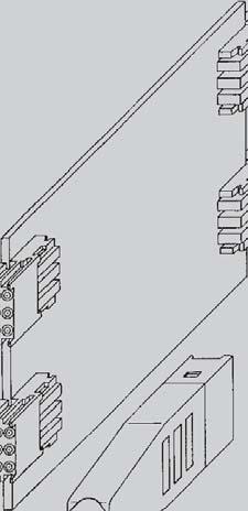
14 AB and AB-friendly connectors Improved guiding with AB-modules: In accordance with the equipment practice each front side arrangement of connectors shall have at least one A-module per slot to ensure that the connector can accommodate ± 2 mm alignment tolerances in rack systems. On some rear I/O arrangements the A-module's alignment capability cannot be utilised, because only B-modules are used for feed through. Consequently AB-modules were introduced to ensure guiding capabilities where formerly only B-modules were used. Those AB-modules represent a combination of A- and B-modules and are specified in CompactPCI by PICMG 2.0 Rev. 3.0 for certain rear I/O applications. The AB-modules have guiding pegs similar (but not mating compatible to prevent mismating) to those of the A-module providing the same proven mating tolerances of ± 2 mm. The AB-modules have no coding center but are fully equiped with contacts in order to maintain the full density as per the B-modules. The AB-female connector mates either with an AB-shroud or with AB-male connectors. The centered pin positions of the shielding rows of male connectors are simply equipped with short spill contacts (if standard connector and shroud are used). This prevents that the guiding peg of the female AB-module stubbing on the feed through contacts of the front side's fixed connector. These fixed connector loadings are called AB-friendly. The AB-male connector will not be equiped with shielded contacts in the centre where the guiding peg will engage Fig. 3: CompactPCI 6U configuration daughtercard backplane rear I/O board
15 CompactPCI general information CompactPCI as a standard is maintained and enhanced by the PCI Industrial Computer Manu facturers Group (PICMG ). It defines a combination of the electrical and logical specifications of the PCI standard and the mechanical specifications of the IEEE 1101 and IEC series of standards. The board connector has been developed from the IEC series of 2.0 mm connectors. The mounting location and dimensions for the 2.0 mm connectors are specified in IEEE Some additional mechanical definitions for 2.0 mm connectors in the Eurocard format are being specified in the VITA 30 draft. J1/P1 and J2/P2 as a minimum. Backplanes should always have the full complement of connectors to be compatible with any type of board. Other international standards are listed in the CompactPCI standard for environmental and As opposed to the CPCI standard (pins numbered from bottom to top), the contact numbers on the connector are numbered from top to bottom (according to the IEC standard). 110 Pins, Type B 22 J5 110 Pins, Type A J4 95 Pins, Type B 19 J3 110 Pins, Type B 22 J2 110 Pins, Type A J1 160 mm mm 100 mm The front panel of CPCI cards may be equipped with additional keying pegs to code individual board types. There is also an extended pin length to re move any electro static charge before contacts on the rear connnectors mate. This pin also functions as a mechanical guide to position the board as straight as possible for insertion. This prevents pin bending and lowers the insertion force. Some applications could require up to 500 pins to be pushed into sockets simultaneously. Connectors for high availability applications (hot swap) come with 3 different lengths of pins for a staged sequence of mate or break of contact. related specifications. This gives CompactPCI a solid foundation of international standards and practices for mechanical robustness. The board format is either a 3U or a 6U Eurocard as defined in IEC There are two or five connectors specified for 3U or 6U boards respectively. Connectors are numbered from J1/ P1 through J5/P5 (bottom to top) on the board or backplane. Slave or peripheral boards need J1/P1 as a minimum, master or system boards need both Connector J1/P1 carries the signals for a 32 bit PCI bus (see table of contact assignments for J1/P1). Connector J2/P2 on a system card has the additional signals for a 64 bit PCI bus and some user-defined I/O (see table of contact assignments for J2/P2). On slave cards all of J2/P2 might be userdefined I/O except the top row which carries the signals for geographical addressing. J3/P3 should be reserved for other system bus definitions. J4/ P4 and J5/P5 are used for I/O or secondary buses, e.g. H.110 in telecom applications or for bridges into other buses like VMEbus. This is used to accommodate two bus platforms in one card cage on one backplane
16 CompactPCI general information Contact assignment on CompactPCI system position (J1/P1) Contact assignment on CompactPCI system position (J2/P2) In mechanical terms J1/P1 is a 25x5 matrix of contacts. Three rows of 5 contacts (rows 12-14) are not used for electrical contacts. Instead, plastic keys of different orientation and configuration are used to key board locations as to system or peripheral slot, voltage options, etc. J2/P2 is a shortened connector with only 22 rows of contacts instead of 25 rows for a standard size. HARTING now offers monolithic versions with J1/P1 and J2/P2 combined in one single connector. This combination together with some space left on the card to fit into guide rails makes maximum use of the 100 mm rear edge of the 3U Eurocard. On a 6U card this connector setup is repeated on J4/P4 and J5/P5. The J3/P3 connector is a shortened version of the 2.0 mm connector with 19 rows of 5 signal contacts. The size results from the height of a 6U board (233 mm) which is more than double the height of a 3U board. All connectors used for CompactPCI are based on a 7 column pitch. The inner 5 columns are used for logic signals and power. The outer columns on either side are reserved for shielding or ground. Executive Member

.")
17 VME64x general information The VMEbus has evolved over a period of more than 25 years to become the leading bus architecture in open industrial applications. The specification is an ANSI norm, the original specification has been extended to become a draft standard VME64x ANSI/VITA This draft standard includes the specification for the 5-row DIN compatible connector (IEC ) and for a centre connector J0/P0 on 6U VME cards, which is identical to J3/P3 in CompactPCI systems. In VMEbus systems it is possible to use custom connectors in the J0/P0 area (e.g. coax connectors). To prevent problems with non-mating backplanes it is strongly recommended to use front panel keying. The IEEE 1101 documents J0/P0 can also be used with rear transition modules for pluggable I/O cabling. As mentioned above, the contacts on this connector may be bussed. One example is the ATM CellBus, which is in the process of being standar dised. The bus on J0/P0 connectors might actually be a plug-on mezzanine backplane rather than conducting traces integrated into the back plane itself. The 2.0 mm J0/P0 connector in VME64x systems is used for additional I/O, for new high speed sub busses or I/O for mezzanine modules, e.g. IP modules on VMEbus boards. The connector is placed on the Eurocard to work in combination with the non-metric original VMEbus connectors DIN type C or the newer 5-row connector har-bus 64. The mounting location and dimensions for the J0/P0 VMEbus connector (IEC ) is specified in IEEE The VMEbus 2.0 mm connector uses 5 columns of signal contacts and optional two additional outer columns on either side for shielding. All 95 signal contacts are user defined
18 Type A Male connectors, straight Number Contact length [mm] of mating termination Identification contacts side side Part number Contact configuration Type A Type A / Type A / / 13.0/ Type A / Type A Type A Thin print part numbers: performance level 1 Bold print part numbers: performance level 2 Connector dimensions see page /
19 Type A Male connectors, straight Number Contact length [mm] of mating termination Identification contacts side side Part number Contact configuration Type A Type A / 14.5/ Type A CompactPCI P1 8.2/ / Type A CompactPCI P / Type A CompactPCI P4 8.2/ / Type A CompactPCI hot swap P1 8.2/ / Thin print part numbers: performance level 1 Bold print part numbers: performance level 2 Connector dimensions see page
![Type A Male connectors, straight Number Contact length [mm] of mating termination](/docs-images/90/104328915/images/20-1.jpg "Identification contacts side side Part number Contact configuration Type A CompactPCI")

![7 11.2 17 01 100 1201 17 01 100 2201 Contact dimensions [mm] Connector dimensions [mm]](/docs-images/90/104328915/images/20-3.jpg "Datum plane depth Board drillings All holes 00.")
20 Type A Male connectors, straight Number Contact length [mm] of mating termination Identification contacts side side Part number Contact configuration Type A CompactPCI computer telephony P4 8.2/ 13.0/ / 14.5/ Type A CompactPCI computer telephony P4 8.2/ / Contact dimensions [mm] Connector dimensions [mm] Datum plane depth Board drillings All holes Thin print part numbers: performance level 1 Bold print part numbers: performance level 2
21 Type B Male connectors, straight Number Contact length [mm] of mating termination Identification contacts side side Part number Contact configuration Type B Type B / Type B / Type B / Type B25 8.2/ / Type B Thin print part numbers: performance level 1 Bold print part numbers: performance level 2 Connector dimensions see page / 13.0/
22 Type B Male connectors, straight Number Contact length [mm] of mating termination Identification contacts side side Part number Contact configuration Type B Type B / Type B22 CompactPCI P / Type B22 CompactPCI computer telephony 8.2/ 13.0/ / 14.5/ Type B22 CompactPCI AB friendly / 3.7/ Type B22 CompactPCI AB friendly 3.7/ 9.7/ / Thin print part numbers: performance level 1 Bold print part numbers: performance level 2 Connector dimensions see page
23 Type B Male connectors, straight Number Contact length [mm] of mating termination Identification contacts side side Part number Contact configuration Type B19 VME J Type B19 VME J / Type B19 VME J / Type B19 VME J Type B19 CompactPCI AB friendly P / 3.7/ Type B19 Compact PCI P3 VME J0 133 Thin print part numbers: performance level 1 Bold print part numbers: performance level 2 Connector dimensions see page /
![Type B Male connectors, straight Drawing Contact dimensions [mm] Connector dimensions [mm] Datum plane depth Dimensions in](/docs-images/90/104328915/images/24-0.jpg "mm Board drillings All holes Contact positions x 1 x 2 19 37.9 18 x 2 (= 36) 22 43.9 21 x 2 (= 42) 25 49.9 24 x 2 (= 48) 00.")
24 Type B Male connectors, straight Drawing Contact dimensions [mm] Connector dimensions [mm] Datum plane depth Dimensions in mm Board drillings All holes Contact positions x 1 x x 2 (= 36) x 2 (= 42) x 2 (= 48)
25 Type AB Male connectors, straight Number Contact length [mm] of mating termination Identification contacts side side Part number Contact configuration Type AB Type AB / Type AB / 13.0/ Contact dimensions [mm] Connector dimensions [mm] Datum plane depth Board drillings All holes Thin print part numbers: performance level 1 Bold print part numbers: performance level
26 Type AB Male connectors, straight Number Contact length [mm] of mating termination Identification contacts side side Part number Contact configuration Type AB Type AB / Type AB / Contact dimensions [mm] Connector dimensions [mm] Datum plane depth Board drillings All holes Thin print part numbers: performance level 1 Bold print part numbers: performance level 2


![Connector dimensions [mm] Datum plane](/docs-images/90/104328915/images/27-6.jpg "depth Board drillings All holes Thin print")
27 Type AB Male connectors, straight Number Contact length [mm] of mating termination Identification contacts side side Part number Contact configuration Type AB Type AB / Type AB / Contact dimensions [mm] Connector dimensions [mm] Datum plane depth Board drillings All holes Thin print part numbers: performance level 1 Bold print part numbers: performance level
28 Type C Male connectors, straight Number Contact length [mm] of mating termination Identification contacts side side Part number Contact configuration Type C Type C / Type C Type C / Type C Type C Thin print part numbers: performance level 1 Bold print part numbers: performance level 2 Connector dimensions see page / 13.0/


![Connector dimensions [mm] Datum plane depth](/docs-images/90/104328915/images/29-5.jpg "Board drillings All holes Thin print part")
29 Type C Male connectors, straight Number Contact length [mm] of mating termination Identification contacts side side Part number Contact configuration Type C / 3.7/ Type C / Contact dimensions [mm] Connector dimensions [mm] Datum plane depth Board drillings All holes Thin print part numbers: performance level 1 Bold print part numbers: performance level
![Type A Female connectors, angled Contact length [mm] No.](/docs-images/90/104328915/images/30-0.jpg "of termination Identification contacts side Part number Type A 17 21")


 CompactPCI computer telephony 90 3.")
 CompactPCI computer telephony 17 23 000")
![4102 Without shielding With shielding Dimensions [mm] Board drillings](/docs-images/90/104328915/images/30-5.jpg "All holes Board drillings 00.")
30 Type A Female connectors, angled Contact length [mm] No. of termination Identification contacts side Part number Type A Type A with upper shield CompactPCI s J1, J4 Lower shield for type A connectors Type A with split upper shield CompactPCI computer telephony J4 Lower shield for type A connectors (rows 1 5) CompactPCI computer telephony Lower shield for type A connectors (rows 15 25) CompactPCI computer telephony Without shielding With shielding Dimensions [mm] Board drillings All holes Board drillings Thin print part numbers: performance level 1 Bold print part numbers: performance level 2 All holes * hole on even contact numbers only needed for lower shielding
![Type B Female connectors, angled Contact length [mm] No.](/docs-images/90/104328915/images/31-0.jpg "of termination Identification contacts side Part number Type B19 17 25 095 1101 95 3.")


 22 43.9 21 x 2 (= 42) 25 49.")
31 Type B Female connectors, angled Contact length [mm] No. of termination Identification contacts side Part number Type B VME, P Type B19 with upper shield CompactPCI, J3 VME, P Lower shield for type B19 connectors Type B Type B22 with upper shield CompactPCI, s J2, J Lower shield for type B22 connectors Type B25 Type B25 with upper shield Lower shield for type B25 connectors Without shielding Contact positions x 1 x x 2 (= 36) x 2 (= 42) x 2 (= 48) With shielding Dimensions [mm] Board drillings All holes Board drillings All holes Thin print part numbers: performance level 1 Bold print part numbers: performance level 2 * hole on even contact numbers only needed for lower shielding
![Type AB Female connectors, angled Contact length [mm] No.](/docs-images/90/104328915/images/32-0.jpg "of termination Identification contacts side Part number Type AB19 95 3.")


 With shielding Dimensions [mm] Board drillings All")
32 Type AB Female connectors, angled Contact length [mm] No. of termination Identification contacts side Part number Type AB Type AB19 with upper shield CompactPCI, RJ3 Lower shield for type AB19 connectors Type AB22 Type AB22 with upper shield CompactPCI, s RJ2, RJ5 Lower shield for type AB22 connectors Type AB25 Type AB25 with upper shield Lower shield for type AB25 connectors Without shielding Contact positions x 1 x x 2 (= 36) x 2 (= 42) x 2 (= 48) With shielding Dimensions [mm] Board drillings All holes Board drillings All holes Thin print part numbers: performance level 1 Bold print part numbers: performance level 2 * hole on even contact numbers only needed for lower shielding


33 Type C Female connectors, angled Contact length [mm] No. of termination Identification contacts side Part number Type C Type C with upper shield Lower shield for type C connectors Without shielding With shielding Dimensions [mm] Board drillings Board drillings All holes All holes Thin print part numbers: performance level 1 Bold print part numbers: performance level 2 * hole on even contact numbers only needed for lower shielding
34 Type Monoblock 47 Male connectors, straight Number Contact length [mm] of mating termination Identification contacts side side Part number Contact configuration Type Monoblock Type Monoblock / Type Monoblock Type Monoblock 47 CompactPCI 8.2/ s P / 3.7 and P Type Monoblock 47 CompactPCI 8.2/ hot swap / Type Monoblock 47 CompactPCI 8.2/ computer / 3.7 telephony 11.2 Thin print part numbers: performance level 1 Bold print part numbers: performance level 2 Connector dimensions see page
![Type Monoblock 47 Male connectors, straight Number Contact length [mm] of mating](/docs-images/90/104328915/images/35-0.jpg "termination Identification contacts side side Part number Contact configuration Type")

![0 17 06 308 2005 Contact dimensions [mm] Connector dimensions [mm] Datum plane depth Board](/docs-images/90/104328915/images/35-2.jpg "drillings All holes Thin print part numbers: performance level 1 Bold print part numbers:")
35 Type Monoblock 47 Male connectors, straight Number Contact length [mm] of mating termination Identification contacts side side Part number Contact configuration Type Monoblock 47 CompactPCI 8.2/ 3.7/ I/O / Type Monoblock 47 CompactPCI AB friendly s P4 and P / 3.7/ Contact dimensions [mm] Connector dimensions [mm] Datum plane depth Board drillings All holes Thin print part numbers: performance level 1 Bold print part numbers: performance level
![Type Monoblock 47 Female connectors, angled Contact length [mm] No.](/docs-images/90/104328915/images/36-0.jpg "of termination Identification contacts side Part number Type Monoblock 47 17 26")

 CompactPCI computer")
")


36 Type Monoblock 47 Female connectors, angled Contact length [mm] No. of termination Identification contacts side Part number Type Monoblock Type Monoblock 47 with upper shield Type Monoblock 47 with upper shield CompactPCI computer telephony Lower shield for type Monoblock 47 connectors Lower shield for type Monoblock 47 connectors (rows 1 22) CompactPCI computer telephony Lower shield for type Monoblock 47 connectors (rows 23 27) CompactPCI computer telephony Lower shield for type Monoblock 47 connectors (rows 37 47) CompactPCI computer telephony Without shielding With shielding Board drillings Board drillings All holes Thin print part numbers: performance level 1 Bold print part numbers: performance level 2 All holes Dimensions [mm] * hole on even contact numbers only needed for lower shielding
37 Notes


![Connector dimensions [mm] Datum plane](/docs-images/90/104328915/images/38-5.jpg "depth Board drillings All holes 00.")
38 Type D Male connectors, straight Number Contact length [mm] of mating termination Identification contacts side side Part number Contact configuration Type D Type D / Type D / 14.5/ Contact dimensions [mm] Connector dimensions [mm] Datum plane depth Board drillings All holes Thin print part numbers: performance level 1 Bold print part numbers: performance level 2
![Type E Male connectors, straight Number Contact length [mm] of](/docs-images/90/104328915/images/39-3.jpg "mating termination Identification contacts side side Part")


![0 17 12 250 2001 Contact dimensions [mm] Connector dimensions](/docs-images/90/104328915/images/39-7.jpg "[mm] Datum plane depth Board drillings All holes Thin print")
39 Type E Male connectors, straight Number Contact length [mm] of mating termination Identification contacts side side Part number Contact configuration Type E Type E / Type E / 14.5/ Contact dimensions [mm] Connector dimensions [mm] Datum plane depth Board drillings All holes Thin print part numbers: performance level 1 Bold print part numbers: performance level
![Type DE Male connectors, straight Number Contact length [mm] of mating termination Identification contacts side side Part](/docs-images/90/104328915/images/40-0.jpg "number Contact configuration Type DE 200 8.2 3.7 17 10 200 1201 17 10 200 2201 Type DE 244 8.2/ 17 10 244 1201 3.7 11.")

40 Type DE Male connectors, straight Number Contact length [mm] of mating termination Identification contacts side side Part number Contact configuration Type DE Type DE / Type DE / 14.5/ Contact dimensions [mm] Connector dimensions [mm] Datum plane depth Board drillings All holes Thin print part numbers: performance level 1 Bold print part numbers: performance level 2
41 Coding keys Coding keys are used to prevent mismating of boards. They can be inserted into the multifunctional area of male and female connectors with special tooling. This can be easily done after the connectors have been pressed in. Coding keys have different bright and pre-defined RAL colours to simplify the identification. In the table below the colours and code numbers in acc. with the IEC are listed. They are used for the following applications: Coding keys for male connectors Cadmium yellow for CompactPCI to identify 3.3 V bus signalling Brilliant blue for CompactPCI to identify 5.0 V bus signalling Reseda green to prevent accidental board insertion in VME64x on CompactPCI applications Strawberry red to prevent accidental board insertion in telephony applications Pastel orange for user defined bus Nut brown for rear I/O and user I/O Coding keys for female connectors Coding key Code number Colour Part number Coding key Code number Colour Part number 3568 Pastel orange RAL Pastel orange RAL Steel blue RAL Steel blue RAL Slate grey RAL Slate grey RAL Cadmium yellow RAL 1021 for CPCI, 3.3 V Cadmium yellow RAL 1021 for CPCI, 3.3 V Reseda green Ral Reseda green Ral Brilliant blue RAL 5007 for CPCI, 5.0 V Brilliant blue RAL 5007 for CPCI, 5.0 V Blue lilac RAL Blue lilac RAL Strawberry red RAL Strawberry red RAL Nut brown RAL All codings are in acc. with the IEC specification 4578 Nut brown RAL

42 Shrouds general information HARTING's shrouds protect the pins protruding the rear side of the backplane from irregular mating tolerances, thus ensuring a quality connection. To accommodate pcb thickness, from 1.6 up to 4 mm nominal, the shrouds have integrated standoffs of corresponding height. Thus forming a one piece solution that reduces assembling cost significantly. The shroud can be mounted without the additional requirement of spacers to ensure the desired pin lengths on the rear side of the pcb. Fixing of the component is carried out on the rear post via a smooth friction fit process. For ease of assembly the same tooling as for the press-in connectors on the front side is utilised for assembly
![Shrouds type A Identification Board thickness [mm] Part number Type A shroud 25 positions Dimensions 1.6 ± 0.4 17 70 000 1001 2.4 ± 0.4 17 70 000 1002 3.2 ± 0.](/docs-images/90/104328915/images/43-0.jpg "4 17 70 000 1003 4.0 ± 0.4 17 70 000 1004 Board thickness [mm] a [mm] 1.6 ± 0.4 3.1 ± 0.05 2.4 ± 0.4 2.3 ± 0.05 3.2 ± 0.4 1.5 ± 0.05 4.0 ± 0.4 0.7 ± 0.")
43 Shrouds type A Identification Board thickness [mm] Part number Type A shroud 25 positions Dimensions 1.6 ± ± ± ± Board thickness [mm] a [mm] 1.6 ± ± ± ± ± ± ± ± 0.05 Dimensions [mm]
![Shrouds type B Identification Board thickness [mm] Part number Type B shroud 25 positions Dimensions 1.6 ± 0.4 17 70 000 2001 2.4 ± 0.4 17 70 000 2002 3.2 ± 0.4 17 70 000 2003 4.0 ± 0.](/docs-images/90/104328915/images/44-0.jpg "4 17 70 000 2004 22 positions 1.6 ± 0.4 17 70 000 4001 2.4 ± 0.4 17 70 000 4002 3.2 ± 0.4 17 70 000 4003 4.0 ± 0.4 17 70 000 4004 19 positions 1.6 ± 0.4 17 70 000 5001 2.4 ± 0.4 17 70 000 5002 3.")
44 Shrouds type B Identification Board thickness [mm] Part number Type B shroud 25 positions Dimensions 1.6 ± ± ± ± positions 1.6 ± ± ± ± positions 1.6 ± ± ± ± Board thickness [mm] a [mm] 1.6 ± ± ± ± ± ± ± ± Contact positions x 1 [mm] x 2 [mm] x 3 [mm] x 2 (= 36) x 2 (= 42) x 2 (= 48) Dimensions [mm]
![Shrouds type AB Identification Board thickness [mm] Part number Type AB shroud 25 positions Dimensions 1.6 ± 0.4 17 70 000 8001 2.4 ± 0.4 17 70 000 8002 3.2 ± 0.4 17 70 000 8003 4.0 ± 0.](/docs-images/90/104328915/images/45-0.jpg "4 17 70 000 8004 22 positions 1.6 ± 0.4 17 70 000 7001 2.4 ± 0.4 17 70 000 7002 3.2 ± 0.4 17 70 000 7003 4.0 ± 0.4 17 70 000 7004 19 positions 1.6 ± 0.4 17 70 000 6001 2.4 ± 0.4 17 70 000 6002 3.")
45 Shrouds type AB Identification Board thickness [mm] Part number Type AB shroud 25 positions Dimensions 1.6 ± ± ± ± positions 1.6 ± ± ± ± positions 1.6 ± ± ± ± Board thickness [mm] a [mm] 1.6 ± ± ± ± ± ± ± ± 0.05 Contact positions x 1 [mm] x 2 [mm] x 3 [mm] x 4 [mm] 19 7 x 2 (= 14) x 2 (= 16) x 2 (= 20) Dimensions [mm]
![Shrouds type C Identification Board thickness [mm] Part number Type C shroud 11](/docs-images/90/104328915/images/46-0.jpg "positions Dimensions 1.6 ± 0.4 17 70 000 3001 2.4 ± 0.4 17 70 000 3002 3.2 ± 0.")
![4 17 70 000 3003 4.0 ± 0.4 17 70 000 3004 Board thickness [mm] a [mm] 1.6 ± 0.4 3.](/docs-images/90/104328915/images/46-1.jpg "1 ± 0.05 2.4 ± 0.4 2.3 ± 0.05 3.2 ± 0.4 1.5 ± 0.05 4.0 ± 0.4 0.7 ± 0.05 00.")
46 Shrouds type C Identification Board thickness [mm] Part number Type C shroud 11 positions Dimensions 1.6 ± ± ± ± Board thickness [mm] a [mm] 1.6 ± ± ± ± ± ± ± ± Dimensions [mm]
![Guiding system Identification Guide pin Part number 17 79 000 0080 Receptacle for guide pin 07 73 000 0280 Dimensions [mm] Guide pin Receptacle for guide pin Board drillings (View-X) 4) General](/docs-images/90/104328915/images/47-0.jpg "information The guide pin solution from HARTING allows safe mating under sometimes extreme conditions. This might be large and heavy boards that bow under their own weight.")


47 Guiding system Identification Guide pin Part number Receptacle for guide pin Dimensions [mm] Guide pin Receptacle for guide pin Board drillings (View-X) 4) General information The guide pin solution from HARTING allows safe mating under sometimes extreme conditions. This might be large and heavy boards that bow under their own weight. Also insufficiently aligned or worn out rack systems can be tolerated better with the use of HARTING's guiding system, which also reduces the potential danger of damaging cards when being forced into flexing racks. The guide pin and receptacle's design solution allows to overcome a 3 mm [.118'] offset between the backplane and the mating daughtercard. The reducing diameter of the pin (from 4.85 mm to 3.4 mm) ensures that its positioning task is smoothly transferred to the connectors as soon as they start to engage. Finally the thin diameter section of the guide pin is no longer positioned by the ferrule of the receptacle, ensuring that the pin is able to freely follow any movement imposed by the engaging connector. This ensures that there is no static stress between the connectors and the guiding system. The rugged metal designed guide pin is screwed to the backplane with standard hexagon screws. Whereas the molded receptacle is designed with four pressin pegs that can be installed to the board together with the connectors. 1) Non-metallised drillings 2) No tracks, except solder eyes 3) Limit area of components (valid for both pcb sides) 4) Recommended board drilling is 3.5 (-0.05) mm Recommended accessories: hexagon nut ISO 4032-M3-8 serrated lock washer DIN 6798-A-3.2 FSt The tooling can be ordered with the part numbers (top tool) and (bottom tool)


48 Special connectors for VME64x DIN Type M male connectors Identification Male connector with angled solder pins Number Contact of contacts arrangement Part No. number Performance levels according to IEC Dimensions mounting hole center line Order high current contacts separately, see page Board drillings Mounting side Y all holes ^= Board drillings depend on type and special contact loading Pre-loaded with special contacts on request Further types see DIN catalogue Dimensions in mm


49 Special connectors for VME64x DIN Complementary type M-flat female connectors Identification Female connector with press-in terminations Number Contact of contacts arrangement Part number Performance levels according to IEC mm Performance level on request Performance level 1 on request Dimensions row position Order high current contacts separately, see page Panel cut out all holes Board drillings Mounting side position row Pre-loaded with special contacts on request Further types see DIN catalogue Dimensions in mm

 I for straight crimp termination acc.")


50 Special connectors for VME64x I II III V VI IV VII High current contacts Part number Identification Performance level 1 Drawing Dimensions in mm High current male contacts for male connectors 1) I for straight crimp termination acc. to DIN A A A ø A ø B wire gauge AWG [mm²] 10 A A A II for straight solder termination Leading contact 10 A A A A A A ø 10 A A A 4.8 III for angled pcb termination max. 40 A* IV max. 40 A* Leading contact max. 40 A* * depending on the pcb design x y High current female contacts for female connectors 1) for type M-flat V for press-in termination for solder termination 40 A A Crimping tool for high current contacts Removal tool VI incl. removal jacket for contact replacement in male and female connectors Replacement removal jacket Removal tool for contact replacement VII in male connectors 1)


 Dimensions")


51 Special connectors for VME64x Male connectors Part number Performance levels according to IEC Number Contact Identification of contacts arrangement 2 1 Male connector* without retention clip 160 z, a, b, c, d ) with retention clip 160 z, a, b, c, d ) Dimensions mounting hole centre line row position without clip with clip Board drillings Mounting side all holes position row Cross section of solder terminations z: A = mm² s a, b, c: A = mm² d: A = mm² A = cross area of contacts * Pre-leading contacts at positions d1, d2, d31 and d32 1) Recommendation for variants with clip: Drillings can be enlarged up to 3.1 mm ø to reduce standard mounting force 2) Special variant with min μm (50 μinch) Au and SnPb on termination Dimensions in mm


52 Special connectors for VME64x Female connectors Part number Performance levels according to IEC Number Contact Identification of contacts arrangement 2 1 Female connectors, straight with press-in terminations with 3.7 mm 160 z, a, b, c, d fixing flange 4.5 / 5 mm 160 z, a, b, c, d mm* 160 z, a, b, c, d without 5 mm 160 z, a, b, c, d fixing flange 17 mm* 160 z, a, b, c, d Dimensions row position Part number Dimension X for row z a b c d / / / / Board drillings Mounting side all holes position row 00. Dimensions in mm 46 1) Selectively gold-plated Further types see DIN catalogue
 with press-in terminations with flange 4.")

53 Special connectors for VME64x Female connectors Number Contact Part number Identification of contacts arrangement Performance level 2 according to IEC Female connectors, straight with switches 1) with press-in terminations with flange 4.5 / 5 mm 160 z, a, b, c, d Dimensions row position Board drillings Mounting side all holes position row 1) Switching elements at positions a21-22, b4-5, b6-7, b8-9 and b10-11 Further types see DIN catalogue Dimensions in mm


54 Special connectors for VME64x Application examples Application 1* Female connector Pin shroud Fixing brackets Backplane Shell housing C Female connector with crimp contacts Locking lever left right Application 2* Female connector Female connector Pin shroud Locking lever for crimp contacts Backplane Application 3 Female connector Pin shroud Shroud insert Female connector Backplane * Only for applications without rear P0-connector
55 6-row Directory chapter 02 with 6 rows, 2.00 mm pitch Page 6-row general information Technical characteristics row Straight male connectors with press-in termination Angled female connectors with press-in termination Angled female connectors with solder (SMC) termination Compatibility with OBSAI
.")


. Figure 2 Coding Pos. 1 / Pos. 2 Flange 02.")
56 6-row General information 6-row General information In comparison to the standard 5-row har-bus HM series, this new 6-row version offers a significantly higher contact density, thus permitting applications where very high contact density is important. Typically, for a signal transmission of 1.5 Gbps it is possible to obtain 7.5 differential pairs per cm of card edge (see figure 1). For a signal transmission of 2.5 Gbps at least 5 differential pairs per cm of card edge can be obtained (see figure 2). Male and female connectors are both available with 72 or 144 contacts and can be supplied in reel or tube packaging. All male connectors can be supplied with end wall, coding pins and guiding system. End wall Guiding system Coding Pos. 1 Female connectors with press-in termination The 6-row female connector needs comparable space on the daughter card as the 5-row versions, as it has similar outer dimensions. Compared to the male connectors, coding pins and a guiding system are available upon request too. Figure 1 Guiding system Male connectors Each contact position can be loaded with any of the 13 different contacts lengths shown (see figure 3). Figure 2 Coding Pos. 1 / Pos. 2 Flange Figure 3 Female connectors in SMC (Surface Mount Compatible) technology Using the reflow soldering process, these 6-row female connectors in SMC technology can be soldered to the PCB at the same time as other SMC components. So the handling cost can be reduced significantly and there is no need for a separate press-in process. These connectors are made from a high temperature plastic material that can withstand up to 260 C (lead free soldering). To hold the connector securely on the PCB before the solder process, kinked contacts are offered as standard on both connector sides. Further SMC information see chapter 01.
57 6-row Technical characteristics Design : complementary to IEC (2 mm hard metric specification) Number of contacts : 72 or 144 Contact spacing : 2.00 mm (1.50 mm between contact rows on the termination side of female connectors) Working current Test voltage U r.m.s. Typical differential data rate : 1.0 A (24 C temp. raise) 1.5 A (52 C temp. raise) 2.0 A (88 C temp. raise) : min. 750 V : Gbps 6-row Temperature range : - 55 C C during reflow soldering max. 260 C (peak temperature) Performance level* : performance level 2 = 250 mating cycles performance level 1 = 500 mating cycles Termination technique : press-in for male and female connectors SMC for female connectors, compatible with lead-free solder process Pcb characteristics : min. 1.4 mm for male and female connectors with press-in terminations 1.6 mm mm for female connectors with SMC terminations Recommended configuration of plated through holes : press-in SMC Plated hole-ø 0.6 ± 0.05 mm mm Hole-Ø 0.7 ± 0.02 mm 0.8 ± 0.02 mm Cu μm μm Sn 5-15 μm 5-15 μm Mating force : < 0.75 N/pin Materials Mouldings : Thermoplastic resin, glass-fibre filled, UL 94-V0 Contacts : Copper alloy Contact surface : Au/Ni Packaging Tube Tape & Reel * Other platings on request : Male connectors and female connectors with press-in terminations : Female connectors with SMC terminations
58 6-row Male connectors straight, with press-in termination 6-row Number Contact length [mm] of mating termination Identification contacts side side Part number Contact configuration Connectors without flange without coding without endwall Connectors without flange without coding with endwall Connector dimensions see pages and The pin types A, B, C R, S, T can be mixed in any configuration. Please request the part number. Thin print part numbers: performance level 1 Bold print part numbers: performance level 2
59 6-row Male connectors straight, with press-in termination Number Contact length [mm] of mating termination Identification contacts side side Part number Contact configuration Connectors with flange without coding without endwall optional coding 2 optional coding 1 6-row Connectors with flange with coding 1 without endwall optional coding 2 optional coding Connectors with flange with coding 2 without endwall Connectors with flange with coding 3 (= coding 1 + 2) without endwall Connector dimensions see pages and The pin types A, B, C R, S, T can be mixed in any configuration. Please request the part number. Thin print part numbers: performance level 1 Bold print part numbers: performance level

![Connector dimensions [mm] Dimensions](/docs-images/90/104328915/images/60-1.jpg "in mm Contact positions x 1 x 2 x 3 72")
 48.")


60 6-row Male connectors straight, with press-in termination 6-row Drawing Connector dimensions [mm] Dimensions in mm Contact positions x 1 x 2 x x 2 (= 22) x 2 (= 46) 48.9 without flange without coding without endwall without flange without coding with endwall Datum plane depth Datum plane depth Board drillings Board drillings All holes All holes
 30.")

61 6-row Male connectors straight, with press-in termination Drawing Connector dimensions [mm] Dimensions in mm 6-row Contact positions x 2 x x 2 (= 22) x 2 (= 46) 54.9 with flange with coding without endwall Datum plane depth optional coding 1 optional coding 2 Board drillings All holes * Non-metallized drillings
62 6-row Female connectors angled, with press-in termination 6-row Number Contact length [mm] of termination Identification contacts side Part number Connectors without flange without coding Connectors with flange without coding Connectors with flange with coding Connectors with flange with coding Connectors with flange with coding 3 (= coding 1 + 2) Connector dimensions see page Thin print part numbers: performance level 1 Bold print part numbers: performance level 2


 55.")

63 6-row Female connectors angled, with press-in termination Drawing Connector dimensions [mm] Dimensions in mm 6-row without flange without coding with flange with coding no coding coding 1 coding 2 coding 3 Contact positions x 1 x 2 x x 2 (= 22) x 2 (= 46) 55.0 Board drillings Board drillings All holes All holes * Non-metallized drillings
64 6-row Female connectors angled, with solder (SMC) termination 6-row Number Contact length [mm] of termination Identification contacts side Part number Connectors without flange without coding Connectors with flange without coding Connectors with flange with coding Connectors with flange with coding Connectors with flange with coding 3 (= coding 1 + 2) Connector dimensions see page Thin print part numbers: performance level 1 Bold print part numbers: performance level 2


![dimensions [mm]](/docs-images/90/104328915/images/65-2.jpg "Dimensions in mm 6-row")


 31.")
 55.")

65 6-row Female connectors angled, with solder (SMC) termination Drawing Connector dimensions [mm] Dimensions in mm 6-row without flange without coding with flange with coding kinked pins at both ends of the connector kinked pins at both ends of the connector no coding coding 1 Contact positions x 1 x 2 x 3 coding 2 coding x 2 (= 22) x 2 (= 46) 55.0 Board drillings Board drillings All holes All holes * Non-metallized drillings
66 Compatibility with OBSAI HARTING is a supporter member of OBSAI since September The Open Base Station Architecture Initiative (OBSAI) has developed a comprehensive set of open specifications for key module interfaces within the base station architecture. This development will enable an open market of base station modules. 6-row The OBSAI architecture provides a clear split in functionality and detailed internal interface specifications. This allows companies to create modules that are truly compatible in all OBSAI compliant base stations. OBSAI provides the entry for a new, competitive market for functionally standardized modules. HARTING s har-bus HM Signal and HM Power connectors meet OBSAI specifications and provide a reliable and cost effective solution for connecting plug-in units to the backplane. The connector solution available from HARTING technology group will offer full compatibility and intermateability with base station modules. HARTING's activities in the wireless market are in line with those of OBSAI. The OBSAI specifications allow HARTING the opportunity to support a large group of wireless base station manufacturers and module manufacturers with unified, state of art interconnection solutions
67 Power Directory chapter 03 Power Page Power general information Technical characteristics Angled male connectors with press-in termination Power Angled male connectors with solder (SMC) termination Straight female connectors with press-in termination
68 Power General information The HM Power connector is designed according to the OBSAI Specification V 1.1. It is well-suited to be used in conjunction with 2 mm connectors. The durability is according to IEC (250 mating cycles). The straight female connector for the backplane is fitted with press-in contacts, the right angled male connector for daugther cards can be supplied with either press-in or PIHIR (Pin In Hole Intrusive Reflow) termination. Loaded with four power contacts, each contact can carry up to C / 80 % derating. With a configuration of two power contacts, GND and ENA, the current carrying capacity is even up to C / 80 % derating per contact. ➁ Power * Current [A] ➀ ➂ The compact, high temperature moulding can be loaded with up to four high current contacts. Four different contact lengths are available from 7.4 mm to mm. This makes sequenced and non sequenced loadings possible (e.g. with GND and ENA). Any other contact assignments, also partially loaded, are available on request. Ambient temperature [ C] ➀ Temperature raise ➁ Derating ➂ Derating curve at I max x 0.8 (DIN EN ) The distance between adjacent contacts is 3 mm, which enables wider pcb traces, larger solder paste areas and an improved heat dissipation. For the female backplane connector no special tooling is necessary due to the flatrock design. For the male connector HARTING offers a special press-in tool (see chapter 15). HARTING's Signal and Power connectors meet OBSAI (Open Base Station Architecture Initiative) specifications and provide a reliable and cost effective solution for connecting plug-in units to the backplane. The connector solutions available from the HARTING technology group will offer full compatibility and intermateability with base station modules. Benefits: Small form factor High current rating up to 23 A per contact (OBSAI configuration) 3 level staggering (or even 4) Flatrock design Matched with 2 mm connectors * Type XL on request
69 Power Technical characteristics Design according : OBSAI System Spezifikation V 1.1 Approvals Underwriters Laboratories Inc. : with their respective ratings documented in file E Number of contacts : up to 4 Contact spacing : 3.00 mm Clearance and creepage distances between contacts : > 2.3 mm Power Working current Test voltage U r.m.s. : 23 A max. (OBSAI configuration) 20 A max. (fully loaded with power contacts) : AC 1500 V min. Temperature range : - 55 C C during reflow soldering 220 C for 2 minutes, 260 C max. short-term Durability as per IEC : Performance level 2 = 250 mating cycles in total. First 125 mating cycles, then 4 days gas test using 0.5 ppm SO 2 and 0.1 ppm H 2S (at C and % humidity). Measurement of contact resistance. The remaining 125 mating cycles are subject to measurement of contact resistance and visual inspection. No abrasion of the contact finish through to the base material. No functional impairment. Termination technique Male connectors Female connectors Mating force Withdrawal force : Press-in or solder termination, suitable for (lead-free) pin-in-hole reflow soldering : Press-in termination : max. 4 N / contact : min. 0.5 N / contact Materials Mouldings : Thermoplastic resin, glass-fibre filled, UL 94-V0 Contacts : Copper alloy Contact surface : Selectively gold plated (contact zone) Contact styles : Standard, leading, lagging Packaging Tube Tape & Reel : Male and female connectors : On request for male solder connectors


![8 17 61 004 2104 Connector dimensions [mm] (View](/docs-images/90/104328915/images/70-5.jpg "magnified) Board drillings All holes All holes 03.")
70 Power Male connectors angled, with press-in termination Power Number Contact length [mm] of termination Identification contacts side Part number Contact loading Connector with same sized contacts Connector with same sized contacts Connector with leading/lagging contacts OBSAI configuration Connector with leading contact Contact dimensions [mm] Connector dimensions [mm] (View magnified) Board drillings All holes All holes ) Non-metallized drillings 2) Type XL on request Tooling see chapter 15


![5 17 61 004 2801 Contact dimensions [mm] Connector](/docs-images/90/104328915/images/71-5.jpg "dimensions [mm] (View magnified) Board drillings All")
71 Power Male connectors angled, with solder (SMC) termination Number Contact length [mm] of termination Identification contacts side Part number Contact loading Connector with same sized contacts Power Connector with leading/lagging contacts OBSAI configuration Contact dimensions [mm] Connector dimensions [mm] (View magnified) Board drillings All holes All holes 1) Non-metallized drillings 2) Type XL on request

![length [mm] of termination Identification](/docs-images/90/104328915/images/72-1.jpg "contacts side Part number Connector Power")

72 Power Female connector straight, with press-in termination Number Contact length [mm] of termination Identification contacts side Part number Connector Power Connector dimensions [mm] Board drillings All holes All holes
73 Micro Card Edge connector Directory chapter 05 Micro Card Edge connector, 0.8 mm pitch Page General information and features Technical characteristics, board dimensions pin connector pin connector MCE

74 Micro Card Edge connector General information HARTING offers the new Micro Card Edge connector in surface mount technology for PCBs with the thickness of 1.6 mm. The new connector is suitable for board-to-board mezzanine as well as for small pluggable daughter card applications. The key feature of the new connector in mezzanine applications is the achievement of flexible staple heights of parallel boards. The HARTING Micro Card Edge connector allows data transfer rates up to 14Gbps and is suitable for highspeed applications in the telecom, medical and industrial markets. The connector is available with 40 or 100 contacts in 0.8 mm pitch. An extremely smooth contact surface achieved by the usage of high performance stamping tools and a special surface finish ensures low insertion forces and a high contact reliability. HARTING s Micro Card Edge connector offers excellent features for high volume manufacturing like tape-andreel packaging and a pad for nozzle in high volume productions. MCE Features n High speed data transmission between mezzanine or daughter card boards in telecom, medical, datacom and industrial applications. n The key feature for mezzanine application is that the distance between parallel boards is flexible by utilizing a small board between the connectors. This gives flexibility in the mechanical design of the system. n SMT termination gives good signal integrity characteristics for the card edge connector
75 Micro Card Edge connector Technical characteristics Contact spacing Working current Test voltage : 0.8 mm : 1.7 A at 80 C ambient : 600 V AC Mating cycles : 200 Number of contacts : 40, 100 Mating card thickness : mm Operating temperature : -55 C up to +125 C Max processing temperature : 230 C for 60 sec. or 260 C for 20 sec. ROHS-compliance : yes Materials Mouldings : LCP, glass-fibre filled, UL 94-V0 Contacts : Copper alloy with Ni plating Contact surface Contact zone : Pd/Ni plating with Au flash Termination zone : Sn/Ni plating MCE Board dimensions min. 20 mm max. Recommended mating card layout 40pin 100pin


76 Micro Card Edge connector 40pin connector Number Identification of contacts Part number Drawing Dimensions in mm Micro Card Edge connector 2800 pieces in a Tape and Reel packaging (14 reels with 200 pcs.) MCE 200 pieces in a Tape and Reel packaging position Single connector sample pick & place pad, self-adhesive position Board layout pin 2 pin 40 pin 39 pin 1 Tape and Reel packaging 20 empty pockets 200 pockets with components 20 empty pockets position 1 trailer leader Reel dimensions (appr. Ø 150 mm) 0,5 (appr. Ø 13 mm) 15 (appr. Ø 380 mm)


 0,5 (appr.")
77 Micro Card Edge connector 100pin connector Number Identification of contacts Part number Drawing Dimensions in mm Micro Card Edge connector 1800 pieces in a Tape and Reel packaging (9 reels with 200 pcs.) 200 pieces in a Tape and Reel packaging position MCE Single connector sample position pick & place pad, self-adhesive Board layout pin 2 pin 100 pin 1 pin 99 Tape and Reel packaging 20 empty pockets 200 pockets with components 20 empty pockets position 1 trailer leader Reel dimensions 6 (appr. Ø 150 mm) 0,5 (appr. Ø 13 mm) 15 (appr. Ø 380 mm)
78 Notes MCE
79 Mini Coax Directory chapter 07 Mini Coax modules (press-in) Page Mini Coax connector system general information Technical characteristics Straight Mini Coax Standard modules for backplane assembly Angled Mini Coax Standard modules for daughtercard assembly Angled Mini Coax single-row modules for daughtercard assembly Mini Coax Mini Coax tooling see chapter
 and IF (Intermediate Frequency) signal transmission and is specified for a frequency range from DC to 2.5 GHz and beyond.")
.")
80 Mini Coax connector system General information The Mini Coax connector is a multi line RF connector for blind mating of board-to-board, boardto-cable or cable-to-cable applications. The Mini Coax connector is mainly used in both RF (Radio Frequency) and IF (Intermediate Frequency) signal transmission and is specified for a frequency range from DC to 2.5 GHz and beyond. Thanks to its compact size (a 10 coaxial contacts connector is as small as a PC's enter key) and excellent crosstalk features, this connector system is ideal for high end equipment within cellular telecom infrastructure. The isolated coaxial lines are implemented in a plastic housing that defines the module size in a metric scale from 1.00, 1.25 and 1.50 SU (SU = System Unit = 25 mm). The Mini Coax connectors are available as straight sockets and right angled plugs. Both types are executed in press-in technology for the PCB (Printed Circuit Board) termination. The straight modules are delivered with an inserted plastic cap that protects the coaxial contacts against dust and dirt, as well as being used as an upper press-in tool. In this way, an easy and safe flat rock process is guaranteed. The contacts of the Mini Coax single-row connector are single line, as opposed to the standard connector. This delivers enhanced performance, especially in terms of isolation, and is also suitable for slim cabinet applications. Mini Coax Fig. 1: Demo board constant mating depth Fig. 2: Cross section of both connector types Mini Coax


81 Mini Coax connector system General information Rx Tx Mini Coax Fig. 3: Typical pcb configurations Radio device card Cable on the backplane side Board-to-backplane connection Backplane frame Fig. 4: Mini Coax backplane feed through
82 Mini Coax Technical characteristics Number of contacts : 1, 2, 4, 6, 8 or 10 coaxial contacts Grid pattern : 4.40 x 6.25 mm (within a twin x between twins); 8.80 mm for Mini Coax single-row connectors Dielectric withstanding Voltage U r.m.s. DC-contact resistance Frequency range : DC 2.5 GHz Return loss : < - 20 db Insertion loss : < 0.25 db Near end crosstalk (NEXT) : Pin distance Board-to-Board Board-to-Cable Cable-to-Cable x = 4.40 mm 50 db 60 db 90 db Mini Coax x = 6.25 mm 60 db 70 db 90 db x = 7.64 mm 75 db 80 db 90 db x = 8.80 mm 75 db x = mm 90 db 90 db 90 db 4,40 7,64 6,25 Fig. 5: Grid pattern Mini Coax Standard Fig. 6: Grid pattern Mini Coax single-row Temperature range : 55 C C Moulding material : Liquid Cristal Polymer (LCP), UL 94-V0 Contact surface Contact zone : Au Termination area Centre pin : Au Ground pin : Ni
83 Mini Coax Technical characteristics Mating cycles : max. 500 Recommended configuration of plated through holes : Tin plated Hole-Ø 1.15 ±0.025 mm PCB (HAL) Cu min. 25 μm acc. EN Sn max. 15 μm Plated hole-ø mm Chemical Hole-Ø 1.15 ±0.025 mm tin plated PCB Cu min. 25 μm Sn min. 0.8 μm Plated hole-ø mm Au / Ni plated PCB Hole-Ø 1.15 ±0.025 mm Cu min. 25 μm Ni 3-7 μm Au μm Plated hole-ø mm Silver plated PCB Hole-Ø 1.15 ±0.025 mm Cu min. 25 μm Ag μm Plated hole-ø mm OSP Hole-Ø 1.15 ±0.025 mm copper plated PCB Cu min. 25 μm Plated hole-ø mm Mating distance : mm Acceptable radial mating offset : max. ± 1.5 mm Mini Coax


84 Mini Coax Standard Straight modules Number of loaded Identification contacts SU positions Part number Mini Coax modules, press-in termination Dimensions , 5, 8, 11, , 5, 8, , 5, , a Mini Coax b View with protection-cap Board drillings Straight Dimension [mm] module a b c 1.50 SU SU SU B, D: position 2, 5, 8, 11, 14 for signal line connector center line Dimensions [mm] c b A, C, E: position 1, 3, 4, 6, 7, 9, 10, 12, 13, 15 for ground-line 1) Non-metallised drillings 2) Details see page 07.05

 Angled Dimension")
![[mm] module a b c 1.50 SU 35.45 32.5 25 1.25 SU 29.15 26.25 18.75 1.00 SU 22.9 20 12.](/docs-images/90/104328915/images/85-2.jpg "5 B, D: position 2, 5, 8, 11, 14 for signal line A, C, E: position 1, 3, 4, 6, 7, 9, 10, 12, 13, 15 for")
![ground-line 1) Non-metallised drillings 2) No tracks, except solder eyes Dimensions [mm] 3) Limit area of](/docs-images/90/104328915/images/85-3.jpg "components (valid for both pcb-sides) 4) Details see page 07.")
85 Mini Coax Standard Angled modules Number of loaded Identification contacts SU positions Part number Mini Coax modules, press-in termination Dimensions , 5, 8, 11, , 5, 8, , 5, , Connector centre line Pcb surface Mini Coax b a Board drillings b c (View magnified) Angled Dimension [mm] module a b c 1.50 SU SU SU B, D: position 2, 5, 8, 11, 14 for signal line A, C, E: position 1, 3, 4, 6, 7, 9, 10, 12, 13, 15 for ground-line 1) Non-metallised drillings 2) No tracks, except solder eyes Dimensions [mm] 3) Limit area of components (valid for both pcb-sides) 4) Details see page ) Press-in zone in any angular position related to it s longitudinal axis possible
 Board drillings B: position 2, 5, 8 for signal line 07.")
![08 Dimensions [mm] A, C: position 1, 3, 4, 6, 7, 9 for ground-line 1) Non-metallised drillings 2) No tracks, except solder eyes 3) Limit area of](/docs-images/90/104328915/images/86-1.jpg "components (valid for both pcb-sides) 4) Details see page 07.")
86 Mini Coax single-row Angled modules Number of loaded Identification contacts SU positions Part number Mini Coax single-row module, press-in termination 3 1 2, 5, Dimensions Pcb surface Mini Coax (View magnified) Board drillings B: position 2, 5, 8 for signal line Dimensions [mm] A, C: position 1, 3, 4, 6, 7, 9 for ground-line 1) Non-metallised drillings 2) No tracks, except solder eyes 3) Limit area of components (valid for both pcb-sides) 4) Details see page ) Press-in zone in any angular position related to it s longitudinal axis possible
87 Mini Coax Directory chapter 08 Mini Coax cable assemblies and accessories Page Mini Coax cable assemblies general information Assemblies with standard modules Assemblies with single-row modules and with heavy duty hoods/housings Accessories Mini Coax Cables


88 Mini Coax General information Mini Coax Cables The Mini Coax product range also includes various cable assemblies and accessories, which provide customers with flexible application options. The Mini Coax cable connector is available as plug and socket and is crimped to a coaxial cable that can be individually assembled with RF-cable connectors (SMA, SMB, N-type ). While delivering high RF transmission performance, the moulded Mini Coax cable assemblies provide robust connections. The various angle mould types meet different cable routing requirements according to the available space. Thanks to various accessories, such as backplane frame, Han housing insert and press-in cable housing, customized connecting requirements can be met. Remark: The cable assemblies and accessories shown are part of the overall product range. Additional, customized parts are available on request
89 Notes Mini Coax Cables

![Dimensions [mm] Cable assembly for mating with](/docs-images/90/104328915/images/90-1.jpg "the angled standard module 1 10 on request Mini")
90 Mini Coax Cable assemblies Number of Identification contacts Part number Drawing Dimensions [mm] Cable assembly for mating with the angled standard module 1 10 on request Mini Coax Cables
![Mini Coax Cable assemblies Identification Part number Drawing Dimensions [mm] Cable](/docs-images/90/104328915/images/91-0.jpg "assembly Mini Coax, 6 position female connector (straight) to SMA crimp connector Hood:")


91 Mini Coax Cable assemblies Identification Part number Drawing Dimensions [mm] Cable assembly Mini Coax, 6 position female connector (straight) to SMA crimp connector Hood: overmoulded with top entry Wiring: 1:1 Length: L = 0.5 m L = 1.5 m L = 2.0 m Cable assembly Mini Coax, 6 pole male Cable: Mini Coax cable Hood: overmoulded with top entry Wiring: 1:1 Mini Coax Cables Length: L = 0.5 m L = 1.5 m L = 2.0 m


92 Mini Coax Cable assemblies Number of Identification contacts Part number Drawing Dimensions [mm] Cable assembly for mating with the angled single-row module 1 3 on request Mini Coax Cables Cable assembly with heavy duty hoods/housings 1 10 on request

 backplane Mini Coax")
 pcb cut-out")
93 Mini Coax Accessories Identification Backplane frame Part number Dimensions [mm] from top of pcb (13.65 with clipped cable connector) backplane Mini Coax Cables contour for polarization pin(s) for cold press-in Board drillings frame (sectional view) pcb cut-out (window) 1) Non-metallized drillings R1.5 max. all edges


: Max. impedance SMA to male 52.")

![length [ps] 262.](/docs-images/90/104328915/images/94-5.jpg "2 Features: system Dimensions [mm] Frequency [GHz] Return loss [db] mated")
94 Mini Coax Accessories Identification Test adapter SMA Mini Coax male for straight modules Part number female for angled modules General information The Mini Coax-to-SMA Adapter can be directly connected to measurement instrument cables. This allows the precise RF transmission characterization of module cards, backplanes and cable assemblies. Electrical characteristics Mini Coax test adapter Impedance 31.5 ps rise time at reference plane (10% - 90%): Max. impedance SMA to male SMA to female * 1.0 Mini Coax Cables Connector Mated SMA to male / female adapter Electrical length [ps] Features: system Dimensions [mm] Frequency [GHz] Return loss [db] mated adapter pairs Insertion loss [db] mated adapter pairs *: Impedance drop is due to the female Mini Coax connector design. Male test adapter Female test adapter
95 Directory chapter 11 Modular metric high speed connectors Page connector system general information Technical characteristics Male and female connectors Accessories and cable assemblies


, thus reducing the skew at high frequencies and considering high signal integrity.")
. Bracket Gasket Fig. 3: 4 cavities bracket and gasket Once plugged, the mated pair shows excellent mating safety.")
96 connector system General information The connector system of HARTING complies with the requirements of IEC and is a compact and robust pcb-to-cable interface with excellent data transmission properties for high-speed net working and telecommunications. All dimensions of the connector are in accordance with IEC 917 and IEEE P 1301 requirements, which allows for easy implementation into both metric and inch-based systems. In addition, supports hot plugging as required by modern bus systems such as CompactPCI, S-bus and VME. allows data transmission up to 2 Gbit/s per pair and is therefore perfectly suited for modern trans mission protocols such as Low Voltage Differential Signals (see Fig. 1). The design of the connector allows differential pairs to be placed horizontally (parallel to the pcb), thus reducing the skew at high frequencies and considering high signal integrity. To reach a screening attenuation of more than 50 db up to 1 GHz, HARTING offers brackets covering each connector in conjunction with a gasket, which is compressed between the bracket and the front panel (see Fig. 3). Bracket Gasket Fig. 3: 4 cavities bracket and gasket Once plugged, the mated pair shows excellent mating safety. Due to the locking levers on both sides of the male connector, the connection withstands a pulling force of up to 80 N (see Fig. 2). The high temperature resistant material of the female connector body supports the safe reflow soldering process. For easy identification of female modules, six different colours are available (see Fig. 4). Fig. 1: Eye diagram of a 1280 MBit signal (512 Bits) The metal shells of the connector are a guarantee for its superior performance in the EMIpolluted environment (see Fig. 2). Fig. 4: Female modules Fig. 2: 360 screened-can construction with locking levers In addition to single connectors, HARTING provides cable assemblies with unshielded twisted pairs or with shielded twisted pairs for high speed applications such as IEEE A crimping tool range for terminating the male connectors is available.
97 Technical characteristics Number of contacts 10 Approvals IEC UL recognized: E Contact pitch Connector pitch 2 mm 6 mm Working current 1.5 A at 70 O C Test voltage U r.m.s. 750 V Contact resistance Insulation resistance 10 Temperature range during reflow soldering -55 O C +125 O C female: max O C for 60 s Mating cycles 250, performance level 2 Terminations Solder buckets (male), AWG 24-30, outer insulation Ø 5.33 ± 0.25 mm Solder pins for ø 0.6 mm min. (female) Insertion force Withdrawal force 10 N max. / module 2 N min. / module (without locking levers) Latching system Locking levers Materials Mouldings Contacts Shells Contact surface Contact zone Male connector: Polyester, UL 94-V0 Female connector: High temperature plastic material, UL 94-V0 Copper alloy Male connector: Stainless steel Female connector: Silver nickel Selectively plated according to performance level


98 Male connectors, straight Female connectors, angled No. of Identification contacts Colour Part number Male connector with solder buckets 10 Black Female connector with solder pins 10 Beige (standard) Red Yellow Green Blue Black Male connector (delivered in piece parts) Manuals for the har-link cable free connector assemblies are available in our online catalogue HARKIS or on demand at your local HARTING representative. Female connector date code Shielding pins Nipple location Shielding pins 0.4 x (0.25) for pin z 0.4 x (0.3) for pins a, b, c, d, e Tooling see chapter 20 Dimensions [mm]


99 Accessories and cable assemblies Identification Part number Drawing Dimensions in mm Bracket with four cavities Board drillings Component side per bracket Gasket with four cavities Standard har-link cable assembly Cable: 5 twisted pairs, AWG 28, shielded, PVC Wiring: 1:1 Length: L = 0.5 m L = 1.0 m L = 2.0 m High end har-link cable assembly Cable: 5 twisted pairs, AWG 30, double shielded, PVC Wiring: 1:1 har link male IDC connector Length: L = 0.5 m L = 1.0 m L = 2.0 m Cable: 5 twisted pairs, AWG 30, double shielded, PVC Wiring: acc. to IEEE 1355 Length: L = 0.5 m L = 1.0 m L = 2.0 m IEEE 1355 wiring Connector 1 Connector 2 2-e 1-a 1-e 2-a 2-d 1-b 1-d 2-b 2-c 2-c Connector 1 Connector 2 1-c 1-c 2-b 1-d 1-b 2-d 2-a 1-e 1-a 2-e
100 Notes
101 Directory chapter 15 Tooling Page Discrete tooling system for volume production Tooling for backplanes Insert blocks for male connectors Repair tooling Power Tooling for angled male connectors Mini Coax Discrete tooling system for volume production Tooling Press-in machines Hand bench presses / pneumatic presses CPM press-in machine 1) ) See separate catalogue
102 Discrete tooling system For economical and safe press-in of connectors with 5+2 and 8+2 rows, HARTING has developed a discrete tooling system. Due to its modular structure it can be adapted to any connector configuration that needs to be pressed-in extremely quickly and securely. Therefore a top and a bottom tool for each connector style is available. These tools are inserted in a top or bottom carrier tool with a groove, thus guaranteeing exact position of the top and bottom tools and the connectors. To use identical carrier tools for all connector configurations, HARTING offer spacer blocks to fill gaps between adjacent top or bottom tools. The carrier tool is either completely filled with top or bottom tools or respective spacer blocks, making it possible to press-in single modules. To press-in female connectors with pre-installed upper shields, separate top and bottom tools are available. For lower shield press-in the tooling can be changed easily. For further information please check our operating instructions or contact your HARTING representative. Top tool carrier Spacer block Spacer block Fig. 1: Basis tools of the discrete tooling system Bottom tool carrier Tooling Basis tools for all connector types Part number connector Tool identification Part number tool 17 xx xxx xxxx Top tool carrier Part number connector Tool identification Part number tool 17 xx xxx xxxx Spacer block 25 mm xx xxx xxxx Bottom tool carrier xx xxx xxxx Spacer block 38 mm xx xxx xxxx Top tool carrier U 17 xx xxx xxxx Bottom tool carrier U 17 xx xxx xxxx Spacer block 0.67 mm (CompactPCI) 17 xx xxx xxxx Spacer block 5 mm xx xxx xxxx Spacer block 44 mm xx xxx xxxx Spacer block 50 mm xx xxx xxxx Centering plate female left xx xxx xxxx Centering plate female right
103 Discrete tooling system Top tool carrier Spacer block Top tool male Backplane Spacer block Bottom tool male Fig. 2: Configuration sample for 6U backplane Bottom tool carrier Tools for straight male connectors Tooling Part number connector Tool identification Part number tool xxx xxxx Top tool, male, type A xxx xxxx Bottom tool, male, type A xxx xxxx Top tool, male, type B xxx xxxx Bottom tool, male, type B xxx xxxx Top tool, male, type B xxx xxxx Bottom tool, male, type B xxx xxxx Top tool, male, type B xxx xxxx Bottom tool, male, type B xxx xxxx Top tool, male, type C xxx xxxx Bottom tool, male, type C Part number connector Tool identification Part number tool xxx xxxx Top tool, male, type D xxx xxxx Bottom tool, male, type D xxx xxxx Top tool, male, type E xxx xxxx Bottom tool, male, type E xxx xxxx Top tool, male, type AB xxx xxxx Bottom tool, male, type AB xxx xxxx Top tool, male, type AB xxx xxxx Bottom tool, male, type AB xxx xxxx Top tool, male, type AB xxx xxxx Bottom tool, male, type AB
104 Discrete tooling system Top tool carrier Spacer block Centering plate Top tool female Daughtercard Spacer block Bottom tool female Fig. 3: Configuration sample for a 6U daughtercard Bottom tool carrier Tools for angled female connectors Part number connector Tool identification Part number tool xxx xxxx Top tool, female, type A xxx xxxx Bottom tool, female, type A xxx xxxx Top tool, female, type B xxx xxxx Bottom tool, female, type B xxx xxxx Top tool, female, type B xxx xxxx Bottom tool, female, type B xxx xxxx Top tool, female, type B xxx xxxx Bottom tool, female, type B xxx xxxx Top tool, female, type C xxx xxxx Bottom tool, female, type C Part number connector Tool identification Part number tool xxx xxxx Top tool, female, type D xxx xxxx Bottom tool, female, type D xxx xxxx Top tool, female, type E xxx xxxx Bottom tool, female, type E xxx xxxx Top tool, female, type AB xxx xxxx Bottom tool, female, type AB xxx xxxx Top tool, female, type AB xxx xxxx Bottom tool, female, type AB xxx xxxx Top tool, female, type AB xxx xxxx Bottom tool, female, type AB Tools for angled shielded female connectors Tooling Part number connector Tool identification Part number tool xxx xxxx Top tool, female, type A upper shield xxx xxxx Top tool, female, type A divided shield computer telephony xxx xxxx Top tool, female, type B upper shield xxx xxxx Top tool, female, type B upper shield xxx xxxx Top tool, female, type B upper shield xxx xxxx Top tool, female, type C upper shield xxx xxxx Top tool, female, type D upper shield xxx xxxx Top tool, female, type E upper shield xxx xxxx Top tool, female, type AB upper shield Part number connector Tool identification Part number tool xxx xxxx Top tool, female, type AB upper shield xxx xxxx Top tool, female, type AB upper shield xxx xxxx Press-in die lower shield type A xxx xxxx Press-in die lower shield type B xxx xxxx Press-in die lower shield type B xxx xxxx Press-in die lower shield type B xxx xxxx Press-in die lower shield type D xxx xxxx Press-in die lower shield type E xxx xxxx Press-in die lower shield type AB xxx xxxx Press-in die lower shield type AB xxx xxxx Press-in die lower shield type AB
105 Tooling for backplanes For 6U backplanes with CompactPCI configuration, HARTING has developed this start-up tooling. The basis is a top tool carrier with tooth inserts, that are engaged alternately. Therefore this tooling assembly can be used without any additional set-up time. The tooth inserts are interchangeable, so that the tooling can be used for other connector configurations as well as for CompactPCI. The bottom tool should preferably be a loadnest, which carries and aligns the pcb. For detailed information please contact your local HARTING representative. À Tooth sheet metal Á Changeable insert  Pcb Loadnest Fig. 4: Configuration samples for CompactPCI backplanes Tooling Tools for straight male connectors Tool identification Part number tool Tool identification Part number tool À Insert top tool for 6U CompactPCI Á Insert top tool for 3U CompactPCI  Insert top tool for rotatable tool changer on request Tooth insert for type Monoblock 47 Tooth insert for type B 19 positions
.")

106 Insert blocks for male connectors The insert blocks can be used to press-in male connectors without any special top tool. These blocks will be put into the connectors manually or automatically (using insertion removal station, see page 15.13). To press-in the connector no precise position is needed and can be done by a simple flat rock die. This will accelerate the cycle time of the press-in process dramatically. Insert blocks are developed for use with a loadnest. Flat rock die Insert block Pcb Fig. 5: Application samples for insert blocks Loadnest Insert blocks for straight male connectors Part number connector Tool identification Quantity and part number tool Tooling xxx xxxx Insert block for type A 1 x or (2 x ) xxx xxxx Insert block for type B 1 x xxx xxxx Insert block for type B 1 x xxx xxxx Insert block for type B 1 x xxx xxxx Insert block for type C 1 x xxx xxxx Insert block for type Monoblock 47 1 x or (1 x and 1 x ) xxx xxxx Insert block for type D 2 x xxx xxxx Insert block for type E 1 x xxx xxxx Insert block for type AB 1 x xxx xxxx Insert block for type AB 1 x xxx xxxx Insert block for type AB 1 x xxx xxxx Insert block for type DE 1 x x xxx xxxx Insert block for type 6-row with 72 contacts 1 x x xxx xxxx Insert block for type 6-row with 144 contacts 1 x Flat rock dies Part number connector Tool identification Part number tool 17 xx xxx xxxx Flat rock die for 6U xx xxx xxxx Flat rock die for 3U The insert block e.g. can be used for the types A, C and Monoblock 47.
107 Repair tooling Identification for use with Part number Drawing Dimensions [mm] Tool kit shroud removal Inserts for shroud Insertion and repair tool for single contact Removal tool for single male contacts Mounting tool for coding key Power Tooling for angled male connectors Tooling Identification for use with Part number Drawing Dimensions [mm] Top tool for angled male connectors Power Bottom tool for angled male connectors Power
108 Mini Coax Discrete tooling system Straight Mini Coax connectors can be pressedin with a flat die and a top tool delivered with the connectors. This top tool can be used as contact protection and remains in the connector until the daughtercard is mated. Angled Mini Coax connectors will be pressed-in with separate top and bottom tools, which will be mounted into a common body. Body Top tool Bottom tool Fig. 6: Configuration for angled modules Tooling Tools for straight modules Part number connector Tool identification Part number tool xxx xxxx 1 SU Mini Coax Standard on request bottom tool xxx xxxx 1.25 SU Mini Coax Standard on request bottom tool xxx xxxx 1.50 SU Mini Coax Standard on request bottom tool Tools for angled modules Part number connector Tool identification Part number tool xxx xxxx Body xxx xxxx 1 SU Mini Coax Standard bottom tool xxx xxxx 1 SU Mini Coax Standard top tool xxx xxxx 1.25 SU Mini Coax Standard bottom tool xxx xxxx 1.25 SU Mini Coax Standard top tool xxx xxxx 1.50 SU Mini Coax Standard bottom tool xxx xxxx 1.50 SU Mini Coax Standard top tool xxx xxxx 1 SU Mini Coax single-row bottom tool xxx xxxx 1 SU Mini Coax single-row top tool
109 Hand bench presses / pneumatic presses Identification Part number Drawing Dimensions in mm Hand bench press Pneumatic press 40 kn Technical characteristics Working stroke 25 mm Press force 15 kn max. Hole ø in the ram ø 10 mm Net weight approx. 23 kg Adaptor for height compensation 1) Technical characteristics Total stroke 48 mm Working stroke 0-6 mm Press force 40 kn max. Air pressure 6 bar Hole ø in the ram ø mm Net weight 136 kg Power supply 110 V / 220 V AC Guide frame with base plate Standard type for pcb size x = 123,5-309,5 mm Long type 2) for pcb size x = 123,5-668,5 mm Tooling Base plate ) suitable for and all CPM machines (see page pp.) 2) not suitable for hand bench press base plate
110 Notes Tooling


 1) the parameters of every pcb layout can be stored, recalled and loaded into the automated press-in programme.")

111 CPM press-in machines The CPM prestige press-in machine with a graphical user interface The CPM prestige is a consequential development of the successful CPM 2001 press-in machines. The excellent design, supported by a wide range of tools presents a convenient, easy and comfortable way of processing backplanes and daughtercards. The machine is fully programmable and is supplied with a graphical user interface for control and visualisation of the complete process. The use of a microprocessor control allows the recognition and storage of different component heights, so that the pressing-in of different components is initiated simultaneously with only one button. The user-friendly touch-screen guides the user through the menu-orientated process controls. Visual guiding system via touch monitor Real photos of connectors and tools The visualisation of the entire press-in process (the position of the connector, press-in forces etc.) allows the rapid recognition and eradication of the possible error sources. With the addition of a barcode reader (1D and 2D) 1) the parameters of every pcb layout can be stored, recalled and loaded into the automated press-in programme. The extensive operation monitor functions simplify the service and support of the machine. Process data Layout with current position highlighted The machine employs the automatic switchoff system autosense, known worldwide for its reliability. The different connector types and the tolerances of the pcb are automatically recognised and taken into consideration at the press-in operation, thus maximising the process security. F Connector type Force vs. distance curve Tooling Pcb surface Board thickness Hole diameter Shown are the four most considerable influences of the press-in process. 1) optional


112 CPM press-in machines Quality control of press-in termination The press-in force correlates with the diameter of the plated through hole and with the friction coefficient of the surface; therefore it can be used for a continuous monitoring of the process. The retention force, as an indirect measure of the normal force, serves to qualify the process or random tests. CPM prestige Part number Technical characteristics Drive Press-in force max. pcb dimensions Floor space Weight Power supply Consumption Colour electro-mechanical, servo 100 kn 600 x 1000 mm 1200 x 1150 mm 980 kg 208 / 380 / 400 / 415 V < 1 kw on request Fig. 7: CPM prestige (incl. PC, control software, barcode reader, keyboard, touch screen) Tooling Built-in features: Process monitoring and quality assurance: l Guiding rails (carbon/spring-loaded) for the secure positioning of the pcb l Touch-screen and Industrial PC with UPS (uninterruptable power supply) l Barcode reader for management ease of press-in programs l All dimensions allow an easy integration into production lines l Touch screen interface with graphical and verbal menus for all machine functions l Autosense: automated press-in interruption at incorrect press-in forces l Storage and validation of all press-in parameters via quality assurance software (press-in force tolerances) l Continuous high-precision measurement and recording of press-in forces and distances l Remote determination of errors and maintenance l High flexibility through a modular tool range Options: l Rotatable tool changer l Insertion removal station


113 CPM press-in machines Insertion removal station Power supply 220 V / 50 Hz Air pressure 6 bar (15-16 l/min.) Part number on request for pcb dimensions of max. 710 mm x 540 mm Principle: À Á  Fig. 8: Bestseller CPM prestige with insertion removal station, adaptable to all HARTING press-in machines. Load all headers with inserts for one press-in cycle Press-in all connectors with a flat die the magnetic plate à Remove the processed pcb from the machine Æ Tooling Ä Å Remove all press-in inserts in one operation Move the next pre-assembled pcb to the insert station Load all headers in one oper ation The insertion removal station has been developed both for the CPM prestige and the CPM 2001/s. It can additionally be used as stand alone equipment


114 CPM press-in machines Today nearly all female connectors are designed for flat rock tooling. For every type of male connector specific tooling and a high degree of X-Y-process accuracy is required. Therefore HARTING offers press-in insert blocks that transfer all well known assembling advantages from female connectors to male headers. Advantages of press inserts Robust tooling No lateral force to pcb hole No abrasion of the contact mating surface by the press tool HARTING has already developed press-in inserts for all major male connector families on 2.54 mm, 2.5 mm and 2 mm pitches. Inserts for any other special components can be developed on request. Tooling The additional process for inserting and removing the press-in inserts can be efficiently done with the insertion removal station. This station removes all pressin inserts with a magnetic plate in one operation and inserts them into the next pre-assembled pcb with the necessary precision. (Principle see page 15.13). The cycle time for loading all headers is between 4 and 6 seconds, independent from the amount of press-in inserts To load the inserts automatically means also that connectors assembled in a wrong way will be recognised and errors consequently prevented.
115 Directory chapter 16 Signal integrity support Page Introduction Simulation and modeling Measurement and verification Test board design Design-in support Signal integrity


116 Introduction HARTING Electronics provides end customers with signal integrity support. We also deliver simulation models and evaluation kits along with our products for signal integrity investigations. The evaluation kits are assembled with SMA's in order to connect them directly with the measurement instruments. Customers benefit from savings in terms of time and the costs for the preliminary evaluation of the connector. We offer test boards suitable for the connector evaluation itself and have built backplanes for measurements within applications such as VME and CompactPCI. Reference structures and well established measurement techniques allow a full de-embedding of the propagation characteristics of the interconnect itself for testing and verification. Furthermore, we have developed a high-speed test backplane with different connector areas and PCB design topologies. We can provide footprint and routing recommendations for each of our products. A variety of test boards and technical data for different products are available on request. HARTING Electronics is also an active member in standardization groups such as VITA, PICMG, OBSAI and supports sub-committees for new interconnect solutions. We engage in close cooperation with universities and industrial partners for research activities. Signal integrity capabilities Simulation and modeling Measurement and verification Test board design Design-in support Simulation and modeling We have the capability to perform full 3D-FEM simulations of the CAD geometry with different well established tools such as CST Microwave Studio and Ansoft HFSS. This enables us to post-process the data for field distribution and full S-Parameter analysis. In conducting SPICE modeling, impedance calculation and field distribution analysis of the geometry, we draw on static 3D-FEM, 2D-FEM and planar field solvers. System simulation, including particular chip, trace, vias and connector sub-circuits are performed with tools such as HSPICE and ADS. Signal integrity We have developed tools for SPICE netlist conversion based on R, L, C, G files for the postprocessing of the data

 up to 12.")


 Far-end crosstalk (FEXT) Power")
 Power sum ACR (PS ACR) Test board")

117 Measurement and verification Time-domain measurements Parameters: Characteristic impedance Propagation delay Reflection Crosstalk Eye-diagram and mask-test Bit-error rate testing (BERT) up to 12.5 Gbps per differential line Frequency-domain measurements ISO/IEC 11801/CAT 5 measurements Parameters: S-parameter analysis (up to 40 GHz) Insertion- and return loss, crosstalk Fourier-transformation, gating, error-location Parameters: Near-end crosstalk (NEXT) Power sum NEXT (PS NEXT) Far-end crosstalk (FEXT) Power sum FEXT (PS FEXT) Return loss Attenuation Attenuation to Crosstalk Ratio (ACR) Power sum ACR (PS ACR) Test board design Design-in support Signal integrity Customized PCB design close to the real application Footprint and routing recommendations Full measurement characterization
118 Notes Signal integrity
119 HARTING customer request form* Should you need a specially loaded connector for your application, please use this request form. Fill out the drawing for the desired connector style and mark each position with the required contact length (A, B,, S, T). Type A Contact dimensions [mm] Type B (19, 22 or 25 positions) Type C Type Monoblock 47 Name: Performance level: n 1 n 2 Company: Drawing: nyes nno Address: Samples: nno nyes, quantity Phone: Volume (pcs./year): Customer request form Fax: * For AB types see page For D, E and DE types see page Special requirements:
120 HARTING customer request form Should you need a specially loaded connector for your application, please use this request form. Fill out the drawing for the desired connector style and mark each position with the required contact length (A, B,, S, T). Type AB (19 positions) Contact dimensions [mm] Type AB (22 positions) Type AB (25 positions) Name: Performance level: n 1 n 2 Company: Address: Drawing: Samples: n yes n no n no n yes, quantity Customer request form Phone: Volume (pcs./year): Fax: Special requirements:
121 HARTING customer request form Should you need a specially loaded connector for your application, please use this request form. Fill out the drawing for the desired connector style and mark each position with the required contact length (A, B,, S, T). Type D Contact dimensions [mm] Type E Type DE Name: Performance level: n 1 n 2 Company: Address: Drawing: Samples: n yes n no n no n yes, quantity Phone: Volume (pcs./year): Customer request form Fax: Special requirements:
122 List of part numbers Part number Page Part number Page Part number Page Part number Page Part number Page Part numbers
123 List of part numbers Part number Page Part number Page Part number Page Part number Page Part number Page Part numbers 02


124 Catalogue order information Please send me further information: Interface Connectors Device Connectivity Industrial Connectors Han Connectors DIN Intelligent Network Solutions Coaxial and Metric Connectors Application brochure TCA Connectors High Speed Backplanes Sender: Company: Department: Name: Prename: Function: Street: Postcode/Town: Country: Phone: Fax: Please send it by post or fax to your local HARTING representatives (see page addresses) or visit us under

125 Tochtergesellschaft / Local subsidiary Fertigungsstätte / Production Plant F & E / R & D Sales Network worldwide Afghanistan see United Arab Emirates Albania see Eastern Europe Argentina Condelectric S.A. Hipólito Yrigoyen 2591, Martínez Buenos Aires Argentina Phone Fax comercial@condelectric.com.ar Armenia see Eastern Europe Australia HARTING Pty Ltd Suite 11 / 2 Enterprise Drive Bundoora 3083, AUS-Victoria Phone Fax au@harting.com Austria HARTING Ges.m.b.H. Deutschstraße 19, A-1230 Wien Phone Fax at@harting.com Azerbaijan see Eastern Europe Bahrain see United Arab Emirates Belgium HARTING N.V./S.A. Z.3 Doornveld 23, B-1731 Zellik Phone Fax be@harting.com Bosnia and Herzegovina see Eastern Europe Brazil HARTING Ltda. Rua Major Paladino 128 Prédio 11 CEP São Paulo SP Brasil Phone Fax br@harting.com Brunei see Singapore Bulgaria see Eastern Europe Canada HARTING Canada Inc Trans-Canada Hwy., Suite 202 St. Laurent, QC, H4S1Z1, Canada Phone Fax info.ca@harting.com China HARTING (Zhuhai) Manufacturing Co., Ltd. Shanghai Branch, Room , No. 1, Hong Qiao Road, Grand Gateway I Xu Hui District, Shanghai , China Phone Fax cn@harting.com Croatia see Eastern Europe Czech Republic HARTING s.r.o. Mlýnská 2, CZ Praha 6 Phone Fax cz@harting.com Denmark HARTING ApS Hjulmagervej 4a DK Vejle Phone Fax dk@harting.com
HARTING. Device Connectivity. People Power Partnership
 07 3 HARTING Device Connectivity People Power Partnership HARTING worldwide Transforming customer wishes into concrete solutions 02 The HARTING Technology Group is skilled in the fields of electrical,
HARTING. Coaxial and Metric Connectors. People Power Partnership
 33 7 HARTING Coaxial and Metric Connectors People Power Partnership Quality Connections Worldwide HARTING was founded in 1945 by the family that still owns the company. Its headquarters are situated in
HARTING Connectors for High Mating Cycles
 HARTING Connectors for High Mating Cycles HARTING worldwide Transforming customer wishes into concrete solutions The HARTING Technology Group is skilled in the fields of electrical, electronic and optical
HARTING. Interface Connectors. People Power Partnership
 11 5 HARTING Interface Connectors People Power Partnership Directory chapter 00 Modular metric high speed connectors, 2.0 mm pitch Page connector system general information......................... 00.04
VMEbus systems System description Technical characteristics System description
 Directory chapter 06 / inverse Page VMEbus systems................................................ 06.02 System description.............................................. 06.03 Technical characteristics..........................................
Transforming customer wishes into concrete solutions
 HARTING News 2013 HARTING worldwide Introduction Transforming customer wishes into concrete solutions The HARTING Technology Group is skilled in the fields of electrical, electronic and optical connection,
07. har-link INTERFACE CONNECTORS
 . INTERFACE CONNECTORS The highest data rates in combination with perfect shielding characterize the connector. This way data can be passed on optimally within the control cabinet. The locking mechanism
07. har-link Interface Connectors
 . Interface Connectors The highest data rates in combination with perfect shielding characterize the connector. This way data can be passed on optimally within the control cabinet. The locking mechanism
hm connectors ept GmbH & Co. KG I Phone +49 (0) 88 61/ I Fax +49 (0) 88 61/55 07 I I
 88 61/ I Fax +49 (0) 88 61/55 07 I I") 26 Definitions 28 Technical specifications 29 Electrical properties 30 Cross talk 31 Hole specifications 32 System modularity 33 Pin lengths 34 Notes 35 hm 2.0 type A 36 hm 2.0 type B25 38 hm 2.0 type
26 Definitions 28 Technical specifications 29 Electrical properties 30 Cross talk 31 Hole specifications 32 System modularity 33 Pin lengths 34 Notes 35 hm 2.0 type A 36 hm 2.0 type B25 38 hm 2.0 type
07. har-link Interface Connectors
 . Interface Connectors The highest data rates in combination with perfect shielding characterize the connector. This way data can be passed on optimally within the control cabinet. The locking mechanism
Extract from new. Device Connectivity catalogue. HARTING har-flex. People Power Partnership
 Extract from new Device Connectivity catalogue HARTING har-flex People Power Partnership . har-flex CONNECTORS The continuous scalability by an even number of contacts, i.e. from 6 to 100, of the HARTING
09. DIN Connectors
 . Connectors Connectors that comply with have been in use for years for both board-to-board applications and cable-to-board applications. Their robustness and universality are legendary. The classic signal
Connectors. product catalog no. 26
 Connectors product catalog no. 26 ept GmbH I Tel. +49 (0) 88 61 / 25 01 0 I Fax +49 (0) 88 61 / 55 07 I E-Mail sales@ept.de I www.ept.de Product Groups Overview Explanation of Symbols Termination Application
09. DIN CONNECTORS
 . 41 612 CONNECTORS Connectors that comply with 41 612 have been in use for years for both board-to-board applications and cable-to-board applications. Their robustness and universality are legendary.
2.0 Connector System IEC Definition of Terms Contact length of the rear and front mating area Connector according to IEC
 Definition of Terms Connector according to The hardmetric connector system ept-hm 2.0 was developed according to the international standard. As a result, a worldwide standard for the combination of PCBs
CompactPCI PowerConnector
 CompactPCI PowerConnector Table of Contents 1 Introduction............................................................. 2 Product Features......................................................... 3 Performance
Summary of shell housings and accessories Shell housing A Shell housing D EMC housing
 Directory chapter 20 Page Summary of shell and accessories........................... 20.02 housing C.......................... 20.04 housing A................................................. 20.08 housing
Catalog C-035 Rev. C
 Catalog C-035 Rev. C P O S I T R O N I C I N D U S T R I E S Today, some customer applications have requirements for high bandwidth transfer between VMEbus cards. Requirements which even the most updated
Han PCB termination. Han-Fast Lock PCB adapter for Han DD PCB adapter for Han DDD module
 Han termination Contents Page Han-Fast Lock... 20.11 adapter for Han DD... 20.13 adapter for Han DDD module... 20.16 adapter for Han 40 A Axial module... 20.18 adapter for Han E... 20.20 adapter for Han
Keying of CompactPCI Boards and Backplanes
 www.picmg.org Keying of CompactPCI Boards and Backplanes PICMG 2.10, Revision 1.0 October 1, 1999 Copyright 1999 PCI Industrial Computers Manufacturers Group (PICMG) The attention of adopters is directed
Millipacs 2mm Hardmetric Product Presentation
 Millipacs 2mm Hardmetric Product Presentation Sep 2014 Millipacs Overview Millipacs is a 2.00 mm modular board to board or cable to board Interconnection system in hardmetric configuration designed in
ERNIPRESS Trapezoidal-Connectors Series TMC
 ERNIPRESS Trapezoidal-Connectors Series TMC Subminiatur-D Connectors to DIN 41 652/IEC 807-3 with Press-fit zone General Solderless press-in technology for connectors in bus systems permits rationalized
Han-Brid. Contents Han-Brid Features Han-Brid Data interfaces Han-Brid Overview Han-Brid Cu
 Contents Page Features... 19.02 Data interfaces... 19.03 Overview... 19.04 Cu... 19.06 F.O.... 19.08 Quintax 3 A... 19.10 RJ45 C... 19.12 USB / FireWire... 19.14 Han 4 A SC... 19.16 Hoods/Housings... 19.18
INTERCONNECT SOLUTIONS
 INTERCONNECT SOLUTIONS Products Overview Connect with Us... Experience Makes the Difference Who We Are We have been designing and manufacturing interconnect products for over 40 years. Today we supply
Han R 23. Circular Connector. Certified acc. to DIN EN ISO 9001 in design/ development, production, installation and servicing.
 Circular Connector Certified acc to DIN EN ISO 9001 in design/ development, production, installation and servicing Data Sheet 0039-4 Circular Connectors Features Size R 23 Outer diameter 26 mm High contact
Directory chapter 05. D-Sub Filter subminiature D connectors, 2.54 mm pitch
 F Directory chapter 05 D-Sub Filter subminiature D connectors, 2.54 mm pitch New Page General information.............................................. 05.02 Technical characteristics..........................................
Technical data: Pin Spacing
 282 Female Connectors, Double-Row Pin Spacing: 3.5 mm Universal connection for all conductor types Unique, compact, double-row connector system for conductor cross sections up to 1.5 mm 2 High-density,
Pixus Technologies Catalog
 The Power of Embedded Ingenuity Pixus Technologies Catalog Kaparel, Ripac, & Vario Brand Products www.pixustechnologies.com sales@pixustechnologies.com S: 96.524.8242 CAN: 59.885.5775 Product Diversity
VEROTEC Electronics Packaging
 VEROTEC Electronics Packaging KM6-HD Subracks Introduction: KM6-HD subracks KM6-HD HEAVY DUTY CARD FRAME Introduction The KM6-HD subrack system, although primarily designed for military use, would suit
UTS UTS. UTS provides a connection that performs faster, easier, safer and more reliable, it makes :
 Company Profile UTS Contents Company profile... 2 Contents... 3 Description... 3 Overview TRIM TRIO... 4 Major features & benefits 5-9 Contact styles... 5 Rapid and secure locking system... 6 Rapid and
Ethernet cabling. B Ethernet cabling. Ethernet cabling overview B 2. Cabling 4-poles IP 20 B.1 8 IP 65 / IP 67 B Cables B Tools B.
 Ethernet cabling Contents Page B Ethernet cabling Ethernet cabling overview B 2 Cabling 4-poles B.1 8 B.1 22 Cables B.1 96 Tools B.1 104 Cabling 8-poles B.2 8 B.2 20 Cables B.2 90 Tools B.2 98 B 1 Profile
EXTreme Guardian Power Connector System
 Exceed high-current and reliability requirements in topend server and high-power applications with Molex s compact,, providing EMI/RFI shielding, overmolding and discretewire options for design flexibility
M12 connector D-coding M12 connector X-coding RJ45 IP20 connector PushPull RJ45 IP65 / IP67 connector
 M12 connectors Directory Chapter Page General information....02 M12 connector D-coding....06 M12 connector X-coding....20 RJ45 IP20 connector....27 PushPull RJ45 IP65 / IP67 connector....46 Han 3 A RJ45
Pixus Technologies Catalog
 The Power of Embedded Ingenuity Pixus Technologies Catalog Kaparel, Ripac, & Vario Brand Products www.pixustechnologies.com sales@pixustechnologies.com US: 96.524.8242 CAN: 59.885.5775 Product Diversity
CMC Hybrid Connectors Standard and Power Versions
 The Molex family of provides a sealed, high-density, modular and cost-effective connection system for heavy-duty, powertrain and body-electronics applications in the transportation industry The CMC connector
HARTING. TCA Connectors. People Power Partnership
 35 4 HARTING TCA Connectors People Power Partnership HARTING worldwide Transforming customer wishes into concrete solutions The HARTING Technology Group is skilled in the fields of electrical, electronic
Connectors DIN 41612/IEC
 Connectors DIN 41612/IEC 60603-2 and completions ERNI-electronic components quality assessed according to CECC 75101-801 2 www.erni.com/contact/ General information The DIN 41612/IEC 60603-2 connector
Elma Bustronic CompactPCI Reference Sheet
 Elma Bustronic CompactPCI Reference Sheet Rev. 4 5.10.10 The cpci reference sheet provides relevant reference material for the CompactPCI product line. The information provided may change at anytime. Elma
SUNCLIX Connection technology for photovoltaics
 SUNCLIX Connection technology for photovoltaics Connection technology for photovoltaics Are you looking for innovative and reliable connection technology for your PV modules, inverters or the complete
Right angle press-fit D-Sub connectors
 Right angle press-fit D-Sub connectors Version in Standard and in Eurostyle General The new generation of right angle D-Sub connectors with press-fit termination of the TMC series are according to DIN
PERFECT HANDLING. PCB Front Panels & Injector/Extractor Handles... Package Your Electronics With Ripac.
 Front Panels & Injector/Extractor Handles... PERFECT HANDLING. Package Your Electronics With Ripac. When it comes to electronics, no one handles today s demanding applications better than Rittal Ripac
This front connection is composed of: 1. Right Angle Male Connector 2. Cable Connector Female
 This specification covers the requirements for the application of Z PACK 2 mm HM Interconnection System for Board to Board Connections and provides information on the standard modules (Types A, B, C, A/B,
Connectors DIN 41612/IEC
 Connectors DIN 41612/IEC 60603-2 and completions General information The DIN 41612/IEC 60603-2 connector family consists of 13 basic sizes and many complementary versions. It was developed for use in 19"
Millipacs 2mm Hard Metric Connector Selector Guide
 Millipacs 2mm Hard Metric Connector Selector Guide Millipacs product family offers 2mm modular Boardto-Board and Cable-to-Board backplane connector solutions. Millipacs product range include low speed
V.5/17. Connectors. product overview. Edition 5
 V.5/17 Connectors product overview Edition 5 Editorial Good connections bear a name: ept Thomas Bernhard Claus Guglhör Guglhör Guglhör ept designs, produces and distributes electronic connectors for highquality
M23 Connectors and cables
 Contents Product Description: SAI M23 Connectors.2 Contact assignment.7 Technical data.8 Overview.10 M23 connector for signal transmission.12 M23 connector for power transmission.18 Moulded M23 cables.22
12. TCA Connectors. Application profile:
 . Connectors The connectors have been specifically developed for the next generation of telecom, medical and industrial applications. The compact connector allows the transmission of highest data rates.
Better all-round. DataVoice Circular connectors STX M12x1 IP67 Connector series for industrial applications. PoE+ 10 GBE. coded.
 Better all-round. X coded D coded 10 GBE PoE+ DataVoice Circular connectors STX M12x1 IP67 Connector series for industrial applications STX M12x1 IP67 connector series With the STX M12x1 IP67 connector
PC/104, PC/104 Plus Specification
 PC/104, PC/104 Plus Specification Industry Standard bus connection systems, typically used on embedded PC applications. Designed for oard-to-oard stacking with a common bus. PC/104 Connectors mm pitch
D-Sub SEaled subminiature D connectors, 2.54 mm pitch
 SE D-Sub SEaled subminiature D connectors, 2.54 mm pitch Page Technical characteristics.......................................... 02 IP 67 versions with turned solder cups......... 04 IP 67 versions with
High Speed Backplane Connectors. Catalog Issued 4-05
 Catalog 773095 Issued 4-05 2 Disclaimer While Tyco Electronics has made every reasonable effort to ensure the accuracy of the information in this catalog, Tyco Electronics does not guarantee that it is
Introduction to High Current Card Edge Connectors
 Introduction to High Current Card Edge Connectors Product Facts Contacts on.100 [2.54] Centerlines Selective gold plating of contacts for high performance at low cost Flow solder applications Glass-filled
ODU MINI-SNAP PC Product Description. ODU MINI-SNAP PC: The Connector with Push-Pull-Locking in Plastic
 ODU MINI-SNAP PC Product Description ODU MINI-SNAP PC: The Connector with Push-Pull-Locking in Plastic Cylindrical Connectors are generally available with several locking mechanisms: The most frequently
ERNIPRESS. DIN 41612/IEC Press-fit connectors catalog E /02 Edition 4
 ERNIPRESS DIN 41612/IEC 60603-2 Press-fit connectors 132 www.erni.com/contact/ Benefits of ERNIPRESS Gas-tight, corrosionproof and mechanically strong connection No soldering errors No terminal stress
CLIPLINE complete. The modular terminal block system for all applications
 CLIPLINE complete The modular terminal block system for all applications CLIPLINE complete All connection technologies, one system With CLIPLINE complete, the unique modular terminal block system from
High-density multi-pin connectors
 High-density multi-pin connectors Mating and mounting conditions to DIN 41612/IEC 60603-2 General With the ever increasing miniaturization and higher packaging densities in highly integrated circuits there
TCA connectors. ept GmbH & Co. KG I Phone +49 (0) 88 61/ I Fax +49 (0) 88 61/55 07 I I
 88 61/ I Fax +49 (0) 88 61/55 07 I I") 10 ept GmbH & Co. KG I Phone +49 (0) 88 61/25 01 0 I Fax +49 (0) 88 61/55 07 I E-mail sales@ept.de I www.ept.de 11 Definitions AdvancedTCA /MicroTCA To give consideration to increasing data traffic and
10 ept GmbH & Co. KG I Phone +49 (0) 88 61/25 01 0 I Fax +49 (0) 88 61/55 07 I E-mail sales@ept.de I www.ept.de 11 Definitions AdvancedTCA /MicroTCA To give consideration to increasing data traffic and
Switch cabinet housings. Distribution housings. Appropriate housings for each application. Our experience. Your safety.
 Switch cabinet housings Distribution housings Appropriate housings for each application Our experience. Your safety. Overview of the housing ranges Mounting rail bus system In-Rail Bus...6 Switch cabinet
Oct 16 Rev D
 Next Generation ARINC 600 Connector Application Specification 114-13272 05 Oct 16 Rev D NOTE All numerical values are in metric units [with U.S. customary units in brackets]. Dimensions are in millimeters
cpci-e3 series Cutting Edge, Push Button, Locking Ejector for CompactPCI Assemblies
 cpci-e3 series Cutting Edge, Push Button, Locking Ejector for CompactPCI Assemblies IEEE 1101.10 and PICMG 2.0 Compliant Compact size and unique aesthetics Innovative positive locking, simple push button
CMC CP Terminals CP 0.635mm (.025 ) CP 1.50mm (.059 ) CP 2.80mm (.110 ) FEATURES AND SPECIFICATIONS
 CP 1.50mm (.059 ) CP 2.80mm (.110 ) FEATURES AND SPECIFICATIONS") FEATURES AND SPECIFICATIONS CMC Connectors sealed, high-density, modular and cost-effective connection system for heavy-duty applications The CMC connector family from Molex is a sealed, high-density connection
FEATURES AND SPECIFICATIONS CMC Connectors sealed, high-density, modular and cost-effective connection system for heavy-duty applications The CMC connector family from Molex is a sealed, high-density connection
HARTING Device Connectivity PushPull
 HARTING Device Connectivity PushPull People Power Partnership O v e r v i e w Device Connectivity: Solutions from HARTING For device manufacturers, Harting offers a comprehensive product line of device
PC/104, PC/104-Plus %ASYç3TACKINGçWITHç0RESS lt 160
 160 PC/104, Contents Introduction 162 Overview 163 The Standard 164 166 167 PC/104 168 170 Accessories: 173 161 Introduction PC/104, Highest Quality for Established Form Factor PC/104 and is a standard
HARTING. News People Power Partnership
 98 42 914 0201 HARTING News 2011 People Power Partnership H A R T I N G w o r l d w i d e Transforming customer wishes into concrete solutions 2 The HARTING Technology Group is skilled in the fields of
WINSTA. Full Line Catalog 2008/2009
 WINSTA Full Line Catalog 2008/2009 5 Contents FULL LINE CATALOG W4, Volume 1 Rail-Mounted Terminal Block Systems FULL LINE CATALOG W4 Rail-Mounted Terminal Blocks Volume 1 X-COM -SYSTEM Terminal Strips
8Rectangular Pin and Socket Connectors
 AMPLIMITE Connectors, Subminiature Series Connectors 109 (Continued) Introduction Product Facts Military qualified connectors conform to the latest amendments of MIL-DTL-24308 Industrial versions available
Datamate High-Reliability Connectors
 Datamate High-Reliability Connectors Industry recognised, British Standard approved Datamate is the field-proven high-reliability range of choice for many industries. Approved to British Standard 9525-F0033
Modular Connector System with High Power, Signal, Fibre-Optic, Coaxial Contacts and Pneumatic Valves
 Modular Connector System with High Power, Signal, Fibre-Optic, Coaxial Contacts and Pneumatic Valves 2 rue René Laennec 51500 Taissy France Fax: 03 26 85 19 08, Tel : 03 26 82 49 29 E-mail:hvssystem@hvssystem.com
PC Board Sockets. Specifications SOCKETS. Surface Mount, Single Piece construction. Throughboard, Two Piece construction. Materials.
 Sockets Contents SMT PCB Sockets Sockets For Ø0.5mm Pin Sockets For Ø0.8mm Pin Sockets For Ø1mm Pin Sockets For Ø2mm Pin Test Sockets IC Socket Strip Dual Row IC Socket Surface Mount, Single Piece construction
DUBOX SHUNTS BOARD/WIRE-TO-BOARD CONNECTORS FEATURES & BENEFITS. Dual-beam contacts for added reliability
 BOARD/WIRE-TO-BOARD CONNECTORS DUBOX SHUNTS FEATURES & BENEFITS Dual-beam contacts for added reliability Slotted cutout in low profile housing simplifies electrical testing Side-by-side and end-to-end
Details of the Han-Terminal block connector Han D AV Han D AV Distributor Han E AV Han ES AV
 Contents -Terminal Block Connectors Page Details of the -Terminal block connector........................ 08.02 D................................................... 08.10 D Distributor...........................................
zqsfp+ Behind Bezel Cage Assembly, Heat Sink, and Light Pipe
 zqsfp+ Behind Bezel Cage Assembly, Heat Sink, and Light Pipe Application Specification 114-32023 02 MAR 12 NOTE i All numerical values are in metric units [with U.S. customary units in brackets]. Dimensions
KM6-II Subracks. APW Electronic Solutions. 152 APW Electronic Solutions Toll Free (800) Fax: (858)
 Fax: (858)") KM6-II Subracks Fully compatible with DIN41494 part 5 and IEC60297-3. KM6-II Standard is available in kit form, offering quick and simple assembly. KM6-II Universal is a highly versatile subrack system,
KM6-II Subracks Fully compatible with DIN41494 part 5 and IEC60297-3. KM6-II Standard is available in kit form, offering quick and simple assembly. KM6-II Universal is a highly versatile subrack system,
02. PushPull CONNECTORS
 . CONNECTORS A distributed automation system does not contain any central automated control cabinets. Controls, sensors and actuators are designed for a high degree of protection (IP 65 / IP 67) and are
02. PushPull CONNECTORS
 . CONNECTORS A distributed automation system does not contain any central automated control cabinets. Controls, sensors and actuators are designed for a high degree of protection (IP 65 / IP 67) and are
ERNI Pre-Alignment Modules
 ERNI Pre-Alignment Modules Provides reliable connection, coding and grounding of plug-in cards ERNI has developed a solution to the dilemma posed by high pin-count hard-metric (HM) connectors and the need
Distribution Systems for Sensors and Actuators
 Distribution Systems for Sensors and Actuators Comprehensive OVERVIEW M12 Distribution Boxes M8 Distribution Boxes Accessories Distribution Systems for sensors and actuators THE RIGHT DISTRIBUTION BOX
Applications
 Han PCB adapter Contents Page Technical characteristics PCB adapter for Han DD... 20.02 Han DD Inserts with PCB adapter... 20.03 Technical characteristics PCB adapter for Han E... 20.04 Han E Inserts with
Vincotech's Compliant Pin. Application Note. Advantages of Vincotech's Power Modules with Press-fit Technology
 Application Note Vincotech's Compliant Pin Advantages of Vincotech's Power Modules with Press-fit Technology Application Note no.: AN_2010-10_001-v04 Table of Contents Revision history:... 3 1 Abstract...
MAY 15 Rev E
 Z-PACK* HS3 and HS3 Plus 6- and10-row Connectors Application Specification 114-13020 05 MAY 15 Rev E NOTE All numerical values are in metric units [with U.S. customary units in brackets]. Dimensions are
PROFIBUS Repeater PRC P PROFIBUS Converter PCF PF P PROFIBUS Converter PCF PF P20.05
 Contents chapter age General information............................... 00 Repeater.......................................... 10 Repeater RC 67-10............................... 10.01 Converter.........................................
Application Specification Universal Power Module (UPM) Connectors 28 MAR 14 Rev K
 Connectors 28 MAR 14 Rev K") Application Specification Universal Power Module (UPM) 114-114 -1103 Connectors 28 MAR 14 Rev K NOTE i All numerical values are in metric units [with U.S. customary units in brackets]. Dimensions are in
Application Specification Universal Power Module (UPM) 114-114 -1103 Connectors 28 MAR 14 Rev K NOTE i All numerical values are in metric units [with U.S. customary units in brackets]. Dimensions are in
Molex s family of high-speed Micro SAS Connectors featuring the Dual-stack Receptacle with Pin Cover
 Design-enhanced Micro SAS connectors now include dual-drive stacked receptacles with an integrated ground plane and a protective pin cover for greater reliability in compact storage applications Molex
Dura-ConTM Hermetic Connectors
 Dura-ConTM Hermetic Connectors Standard Connectors With High Performance Hermetic Seals Catalog cinch.com Cinch Dura-Con Hermetic Connectors offers a high performance hermetic seal designed into our standard
SEPTEMBER C.CS.1000 / GB
 SEPTEMBER 2005 - C.CS.1000 / GB C R I M P F L E X C O N N E C T O R S CRIMPFLEX connectors TECHNICAL DATA MATERIAL Phosphor bronze MALE SOLDER TAB PLATING The standard connector is tin plated (thickness
Next Generation ARINC 600 Connector
 Next Generation ARINC 600 Connector Application Specification 114-13272 29 NOV 12 NOTE NOTE i All numerical values are in metric units [with U.S. customary units in brackets]. Dimensions are in millimeters
MULTIGIG RT 2, RT 2-R, and RT 3 Signal Connectors
 MULTIGIG RT 2, RT 2-R, and RT 3 Signal Connectors Application Specification 114-163004 21 MAR 18 Rev A Abstract This specification covers the requirements for application of MULTIGIG RT 2, RT 2-R, and
Amphenol ABSI VME64x Datasheet
 Amphenol ABSI VME64x Backplanes Amphenol ABSI s VME64x high performance backplanes are available in both 3U & 6U form factors. All VME backplanes are compliant to VITA VME64x specifications. ABSI can customize
Applications & Features, Type SSMP When using blind mate connectors in an application, careful consideration has to be given to choosing the right con
 SSMP Push-On Connectors & Adapters THE SSMP (Sub-Sub-Miniature-Push-On) is a 1.7 mm connector, using solid dielectric interface. The connector is 70% of the size of the SMP and therefore allows even higher
I N T E R C O N N E C T A P P L I C A T I O N N O T E. Z-PACK TinMan Connector Routing. Report # 27GC001-1 May 9 th, 2007 v1.0
 I N T E R C O N N E C T A P P L I C A T I O N N O T E Z-PACK TinMan Connector Routing Report # 27GC001-1 May 9 th, 2007 v1.0 Z-PACK TinMan Connectors Copyright 2007 Tyco Electronics Corporation, Harrisburg,
CHOGORI USA. CAC3 POWER SUPPLY Connector USER-FRIENDLY PERFORMANCE ENGINEERED CONFIGURABLE STANDARD CIRCUIT CONFIGURATIONS
 CHOGORI USA CAC3 POWER SUPPLY Connector USER-FRIENDLY PERFORMANCE ENGINEERED CONFIGURABLE Fast and convenient twist locking system. Ergonomic latch design provides easy operation. Safe,Electric shock resistant.
FOR PC BOARD TO FLAT CABLE
 AXM FOR PC BOARD TO FLAT CABLE MIL CONNECTORS (AXM) Density mounting Long lever type Short lever type Compliance with RoHS Directive FEATURES 1. High density mounting is possible. Even with mounting right
Never Beaten by Seasons
 Never Beaten by Seasons Buccaneer For Data Frozen Winters! Torrential Springs! Blistering Summers! Dusty Autumns! The Buccaneer range of IP68 waterproof connectors for Ethernet, USB, Mini USB and FireWire.
Meet requirements of USB 2.0
 NEW Meet requirements of USB.0 UX Series Features 1. Certified to perform as required in USB.0 Standard Tested and certified by USB Association approved laboratory the connectors will perform at transmission
D-SUBMINIATURE PIN-IN-PASTE CONNECTORS
 INPUT/OUTPUT CONNECTORS D-SUBMINIATURE PIN-IN-PASTE CONNECTORS OVERVIEW The D-Subminiature connectors are one of the most popular I/O solutions, addressing segments such as Telecommunications, Industrial,
Ø 11,4 21,5. M9 x 0,5 Ø 12 Ø 11,4. M9 x 0,5 Ø 12. M9 x 0,5
 Subminiature 7 series Screw termination M9 8 contacts Degree of protection IP7 Solder termination Moulded versions Diameter, mm Male angled connector 8,, Ø,, Contacts Cable outlet Ordering-No. 99 00 70
High-density multi-pin connectors
 High-density multi-pin connectors Mating and mounting conditions to DIN 41612/IEC 60603-2 General With the ever increasing miniaturization and higher packaging densities in highly integrated circuits there
Operating voltages up to 40 kvdc Operating current up to 30 Amps Advanced contact technology Silver plated and gold plated contacts available High
 Operating voltages up to 40 kvdc Operating current up to 30 Amps Advanced contact technology Silver plated and contacts available High performance insulation material General characteristics and technical
CROWN CLIP Series Sockets
 OWN LIP Series Sockets Product Facts ompact design High performance OWN BND contacts urrents to 350 mps 1 Mates with solid or laminated blades Supports true hot-plug (current interruption)2 Float-mount
Datasheet for
 80 Morgan Street Rockford, Illinois 60 800-435-93 Datasheet for 76650-05 General Information Part Number: 76650-05 Manufacturer: Molex / Waldom Title: Deluxe Splashproof Application Kit Includes USB Type