Physics 536 Spring Illustrating the FPGA design process using Quartus II design software and the Cyclone II FPGA Starter Board.
|
|
|
- Bonnie Franklin
- 6 years ago
- Views:
Transcription
1 Physics 536 Spring 2009 Illustrating the FPGA design process using Quartus II design software and the Cyclone II FPGA Starter Board.
2 Digital logic: Equivalent to a large number of discrete logic elements NOT a microprocessor (although microprocessors can be implemented in an FPGA design) High density: All the logic is inside a single chip No need for interconnecting traces on PCB between logic circuits Reprogrammable: Designs can be changed after the hardware has been manufactured High-level design software optimizes the usage of limited resources
3 Both companies produce competitive products neither is endorsed. Other companies exist... We use Altera tools to demonstrate the design process. Xilinx has a similar set of tools. Conceptually, the design process is the same.

4 Altera EP2C20F484C7N $56.30 from Digi-Key Configuration device stores the design that is automatically downloaded when power is applied.
5 Implement a 4-input XOR function: Output will be high only when exactly one input is high. Use KEY[0..3] as inputs. Show output on green LED. Boolean algebra: We could simplify this, but choose not to.
6 Design entry: Schematic entry High level language Synthesis: Translating design into logic elements Simulation: Validate design logic Fitting: Implementing logic using FPGA resources


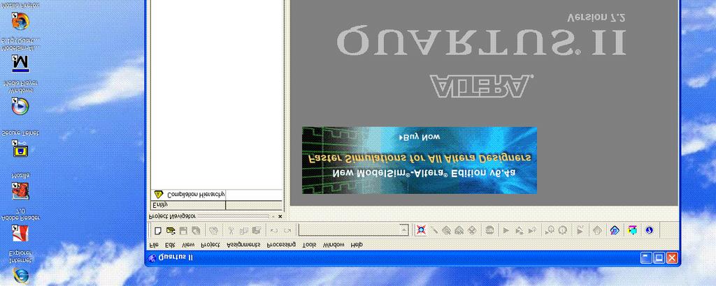
7 Double click here Please be patient... Altera software is installed under C:\Altera\...

8


9 This should be correct...
10
11 File New Project Wizard... What is the working directory for this project? H:\Physics536 What is the name of this project? FirstExample What is the name of the top-level entity...? FirstExample (default) Then click Next >... Click Yes to create the directory. No need to add design files, so click Next >.

12 Select the device: Family: Cyclone II Device: EP2C20F484C7 Then click Finish.
13 If you can t get something simple to work, don t expect to be able to do anything complicated... A much simpler design: Input KEY0 Output to green LEDG0 KEY[0] Input pin Buffer Output pin LEDG[0]

14 File New Block Diagram/Schematic File Add components Add wires

15 Click on navigate to.../primitives/pin/input Click OK, click to place the pin. Do the same for the output pin.
16 Buffers can be used to drive special signals in the FPGA. In this case we don t need anything special so we can select.../primitives/buffer/wire Click the Wire tool ( the pins to the buffer. ) and connect

17 Double-click on the text associated with the pins Change input pin name to KEY[0] and output pin name to LEDG[0].
18 File Save Project Processing Start Compilation Success? If not, fix the problem; try again. Look at resource usage: Total logic elements: 0/18,752 (0%) Total pins: 2/315 (<1%) Not too surprising... But wait... how does it know which pins are physically wired to KEY[0] and LEDG[0]?

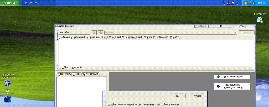
19 Pins can be assigned individually: Assignments Pins Or imported from a file: Assignments Import Assignments C:\Altera\Kits\CycloneII_Starter_Kit-v1.0.0/....../Examples/CII_Starter_demonstrations/design_files/CII_Starter_pin_assignments.csv Don t forget to re-compile the design.

20 Plug in and turn on the DC power Plug in the USB cable. Tools Programmer Start This file contains the configuration data to be downloaded into the FPGA.
21 Sort of... Pins are pulled high via 10k resistors. Low-pass filter to prevent the switches from bouncing.
22 Invert the KEY[0..3] inputs before assigning them to D 0, D 1, D 2, D 3. Use.../primitives/logic/not for inverter Implement the logic: Use 4-input AND and 4-input OR gates:.../primitives/logic/and4.../primitives/logic/or4

23 Can you spot the mistake? The compiler certainly can!

24 We need to specify all possible inputs. File New... Other Files Waveform Vector File Right-click here.

25 Right-click under Name Insert Node or Bus... Insert

26 Left-click on the KEY signal. Left-click on the c, then OK File Save... H:\Physics536\FirstExample\Waveform1.wvf

27 Processing Simulator Tool Simulation input: H:\Physics536\FirstExample\Waveform1.wvf Click Start, then Open to examine the output.

28 Does this look right? We should expect only 1110, 1101, 1011 and 0111 to give and output of 1... Check the timing report...
29 Longest tpd (propagation delay) from source pin KEY[1] to destination pin LEDG[0] is ns. Increase period of each input vector from 10ns to 50 ns...

30 Now this looks like what one would expect. Try downloading the FPGA with this configuration and try it out.
31 This document was created with Win2PDF available at The unregistered version of Win2PDF is for evaluation or non-commercial use only.
CET4805 Component and Subsystem Design II. EXPERIMENT # 5: Adders. Name: Date:
 EXPERIMENT # 5: Adders Name: Date: Equipment/Parts Needed: Quartus II R Web Edition V9.1 SP2 software by Altera Corporation USB drive to save your files Objective: Design a half adder by extracting the
FPGA Introductory Tutorial: Part 1
 FPGA Introductory Tutorial: Part 1 This tutorial is designed to assist in learning the basics of the Altera Quartus II v9.0 software. Part 1 of the tutorial will cover the basics of creating a Project,
EMT1250 LABORATORY EXPERIMENT. EXPERIMENT # 10: Implementing Binary Adders. Name: Date:
 EXPERIMENT # 10: Implementing Binary Adders Name: Date: Equipment/Parts Needed: PC (Altera Quartus II V9.1 installed) DE-2 board Objective: Design a half adder by extracting the Boolean equation from a
EE 231 Fall Lab 1: Introduction to Verilog HDL and Altera IDE
 Lab 1: Introduction to Verilog HDL and Altera IDE Introduction In this lab you will design simple circuits by programming the Field-Programmable Gate Array (FPGA). At the end of the lab you should be able
NIOS CPU Based Embedded Computer System on Programmable Chip
 1 Objectives NIOS CPU Based Embedded Computer System on Programmable Chip EE8205: Embedded Computer Systems This lab has been constructed to introduce the development of dedicated embedded system based
SCHEMATIC DESIGN IN QUARTUS
 SCHEMATIC DESIGN IN QUARTUS Consider the design of a three-bit prime number detector. Figure 1 shows the block diagram and truth table. The inputs are binary signals A, B, and C while the output is binary
CPE 200L LABORATORY 4: INTRODUCTION TO DE2 BOARD UNIVERSITY OF NEVADA, LAS VEGAS GOALS: BACKGROUND:
 CPE 200L LABORATORY 4: INTRODUCTION TO DE2 BOARD DEPARTMENT OF ELECTRICAL AND COMPUTER ENGINEERING UNIVERSITY OF NEVADA, LAS VEGAS GOALS: Getting familiar with DE2 board installation, properties, usage.
Lab 6: Integrated the Decoder with Muti-bit Counter and Programming a FPGA
 Lab 6: Integrated the Decoder with Muti-bit Counter and Programming a FPGA For your report: The problem written in English The flowchart or function table to solve the problem if it is necessary The design
EMT1250 LABORATORY EXPERIMENT. EXPERIMENT # 6: Quartus II Tutorial and Practice. Name: Date:
 EXPERIMENT # 6: Quartus II Tutorial and Practice Name: Date: Equipment/Parts Needed: Quartus II R Web Edition V9.1 SP2 software by Altera Corporation USB drive to save your files Objective: Learn how to
CET4805 Component and Subsystem Design II. EXPERIMENT # 2: VHDL(VHSIC Hardware Descriptive Language) Name: Date:
 Name: Date:") EXPERIMENT # 2: VHDL(VHSIC Hardware Descriptive Language) Name: Date: Equipment/Parts Needed: Quartus II R Web Edition V9.1 SP2 software by Altera Corporation USB drive to save your files Objective: Learn
EXPERIMENT # 2: VHDL(VHSIC Hardware Descriptive Language) Name: Date: Equipment/Parts Needed: Quartus II R Web Edition V9.1 SP2 software by Altera Corporation USB drive to save your files Objective: Learn
Terasic DE0 Field Programmable Gate Array (FPGA) Development Board
 Development Board") Lecture FPGA-01 DE0 FPGA Development Board and Quartus II 9.1 FPGA Design Software Terasic DE0 Field Programmable Gate Array (FPGA) Development Board 1 May 16, 2013 3 Layout and Components of DE0 May 16,
Lecture FPGA-01 DE0 FPGA Development Board and Quartus II 9.1 FPGA Design Software Terasic DE0 Field Programmable Gate Array (FPGA) Development Board 1 May 16, 2013 3 Layout and Components of DE0 May 16,
EE 231 Fall EE 231 Lab 2
 EE 231 Lab 2 Introduction to Verilog HDL and Quartus In the previous lab you designed simple circuits using discrete chips. In this lab you will do the same but by programming the CPLD. At the end of the
Altera Quartus II Tutorial ECE 552
 Altera Quartus II Tutorial ECE 552 Quartus II by Altera is a PLD Design Software which is suitable for high-density Field-Programmable Gate Array (FPGA) designs, low-cost FPGA designs, and Complex Programmable
Laboratory 4 Design a Muti-bit Counter
 Laboratory 4 Design a Muti-bit Counter Background A. Approach I: Design 3-bit counter with and clear T-type flip-flop is shown in Figure 1. A T flip-flop is obtained from a JK flip-flop by tying the J
2 nd Year Laboratory. Experiment: FPGA Design with Verilog. Department of Electrical & Electronic Engineering. Imperial College London.
 Department of Electrical & Electronic Engineering 2 nd Year Laboratory Experiment: FPGA Design with Verilog Objectives By the end of this experiment, you should know: How to design digital circuits using
Quartus II Introduction Using Schematic Design
 Quartus II Introduction Using Schematic Design This tutorial presents an introduction to the Quartus R II CAD system. It gives a general overview of a typical CAD flow for designing circuits that are implemented
EMT1250 LABORATORY EXPERIMENT. EXPERIMENT # 7: VHDL and DE2 Board. Name: Date:
 EXPERIMENT # 7: VHDL and DE2 Board Name: Date: Equipment/Parts Needed: Quartus II R Web Edition V9.1 SP2 software by Altera Corporation USB drive to save your files Objective: Learn how to create and modify
Laboratory 4 Design a Muti-bit Counter and Programming a FPGA
 Laboratory 4 Design a Muti-bit Counter and Programming a FPGA For your report: The problem written in English The flowchart or function table to solve the problem if it is necessary The design entry included
Tutorial on Quartus II Introduction Using Schematic Designs
 Tutorial on Quartus II Introduction Using Schematic Designs (Version 15) 1 Introduction This tutorial presents an introduction to the Quartus II CAD system. It gives a general overview of a typical CAD
UNIVERSITI MALAYSIA PERLIS
 UNIVERSITI MALAYSIA PERLIS SCHOOL OF COMPUTER & COMMUNICATIONS ENGINEERING EKT 124 LABORATORY MODULE INTRODUCTION TO QUARTUS II DESIGN SOFTWARE : INTRODUCTION TO QUARTUS II DESIGN SOFTWARE OBJECTIVES To
UNIVERSITY OF CALIFORNIA, DAVIS Department of Electrical and Computer Engineering. EEC180A DIGITAL SYSTEMS I Winter 2015
 UNIVERSITY OF CALIFORNIA, DAVIS Department of Electrical and Computer Engineering EEC180A DIGITAL SYSTEMS I Winter 2015 LAB 1: Introduction to Quartus II Schematic Capture and ModelSim Simulation This
QuartusII.doc 25/02/2005 Page 1
 1 Start Icon... 2 1.1 The Quartus II Screen... 2 2 Project creation... 2 3 Schematic entry... 5 3.1 Create new drawing... 5 3.2 Symbol selection... 7 3.3 Placement of an AND gate... 8 3.4 Deleting a symbol...
Laboratory Exercise 8
 Laboratory Exercise 8 Memory Blocks In computer systems it is necessary to provide a substantial amount of memory. If a system is implemented using FPGA technology it is possible to provide some amount
Tutorial on Quartus II Introduction Using Verilog Code
 Tutorial on Quartus II Introduction Using Verilog Code (Version 15) 1 Introduction This tutorial presents an introduction to the Quartus II CAD system. It gives a general overview of a typical CAD flow
NIOS CPU Based Embedded Computer System on Programmable Chip
 NIOS CPU Based Embedded Computer System on Programmable Chip 1 Lab Objectives EE8205: Embedded Computer Systems NIOS-II SoPC: PART-I This lab has been constructed to introduce the development of dedicated
CSE P567 - Winter 2010 Lab 1 Introduction to FGPA CAD Tools
 CSE P567 - Winter 2010 Lab 1 Introduction to FGPA CAD Tools This is a tutorial introduction to the process of designing circuits using a set of modern design tools. While the tools we will be using (Altera
ECSE-323 Digital System Design. Lab #1 Using the Altera Quartus II Software Fall 2008
 1 ECSE-323 Digital System Design Lab #1 Using the Altera Quartus II Software Fall 2008 2 Introduction. In this lab you will learn the basics of the Altera Quartus II FPGA design software through following
University of Florida EEL 3701 Dr. Eric M. Schwartz Madison Emas, TA Department of Electrical & Computer Engineering Revision 1 5-Jun-17
 Page 1/14 Example Problem Given the logic equation Y = A*/B + /C, implement this equation using a two input AND gate, a two input OR gate and two inverters under the Quartus environment. Upon completion
Lab 2: Introduction to Verilog HDL and Quartus
 Lab 2: Introduction to Verilog HDL and Quartus September 16, 2008 In the previous lab you designed simple circuits using discrete chips. In this lab you will do the same but by programming the CPLD. At
E85: Digital Design and Computer Engineering Lab 2: FPGA Tools and Combinatorial Logic Design
 E85: Digital Design and Computer Engineering Lab 2: FPGA Tools and Combinatorial Logic Design Objective The purpose of this lab is to learn to use Field Programmable Gate Array (FPGA) tools to simulate
Introduction to VHDL Design on Quartus II and DE2 Board
 ECP3116 Digital Computer Design Lab Experiment Duration: 3 hours Introduction to VHDL Design on Quartus II and DE2 Board Objective To learn how to create projects using Quartus II, design circuits and
Quartus II Introduction Using Verilog Design
 Quartus II Introduction Using Verilog Design This tutorial presents an introduction to the Quartus R II CAD system. It gives a general overview of a typical CAD flow for designing circuits that are implemented
QUARTUS II Altera Corporation
 QUARTUS II Quartus II Design Flow Design Entry Timing Constraints Synthesis Placement and Routing Timing, Area, Power Optimization Timing and Power Analyzer Optimized Design 2 Can I still use a Processor?
Tutorial for Altera DE1 and Quartus II
 Tutorial for Altera DE1 and Quartus II Qin-Zhong Ye December, 2013 This tutorial teaches you the basic steps to use Quartus II version 13.0 to program Altera s FPGA, Cyclone II EP2C20 on the Development
Chip Design with FPGA Design Tools
 Chip Design with FPGA Design Tools Intern: Supervisor: Antoine Vazquez Janusz Zalewski Florida Gulf Coast University Fort Myers, FL 33928 V1.9, August 28 th. Page 1 1. Introduction FPGA is abbreviation
PART 1. Simplification Using Boolean Algebra
 Name EET 1131 Lab #5 Logic Simplification Techniques OBJECTIVES: Upon completing this lab, you ll be able to: 1) Obtain the experimental truth table of a logic circuit. 2) Use Boolean algebra to simplify
Engineering 303 Digital Logic Design Spring 2017
 Engineering 303 Digital Logic Design Spring 2017 LAB 1 Introduction to Combo Logic and Quartus Deliverables: 0) A Simple Verilog Combinatorial Circuit 1) A Simple Block Diagram Combinatorial Circuit 2)
Programmable Logic Design Techniques I
 PHY 440 Lab14: Programmable Logic Design Techniques I The design of digital circuits is a multi-step process. It starts with specifications describing what the circuit must do. Defining what a circuit
Chapter 2 Getting Hands on Altera Quartus II Software
 Chapter 2 Getting Hands on Altera Quartus II Software Contents 2.1 Installation of Software... 20 2.2 Setting Up of License... 21 2.3 Creation of First Embedded System Project... 22 2.4 Project Building
EXPERIMENT 1. INTRODUCTION TO ALTERA
 EXPERIMENT 1. INTRODUCTION TO ALTERA I. Introduction I.I Objectives In this experiment, you will learn computer aided digital design and verification of it using Field Programmable Gate Arrays (FPGA).
Quick Tutorial for Quartus II & ModelSim Altera
 Quick Tutorial for Quartus II & ModelSim Altera By Ziqiang Patrick Huang Hudson 213c Ziqiang.huang@duke.edu Download & Installation For Windows or Linux users : Download Quartus II Web Edition v13.0 (ModelSim
ANADOLU UNIVERSITY DEPARTMENT OF ELECTRICAL AND ELECTRONICS ENGINEERING. EEM Digital Systems II
 ANADOLU UNIVERSITY DEPARTMENT OF ELECTRICAL AND ELECTRONICS ENGINEERING EEM 334 - Digital Systems II LAB 1 - INTRODUCTION TO XILINX ISE SOFTWARE AND FPGA 1. PURPOSE In this lab, after you learn to use
University of Florida EEL 3701 Dr. Eric M. Schwartz Department of Electrical & Computer Engineering Revision 0 12-Jun-16
 Page 1/14 Quartus Tutorial with Basic Graphical Gate Entry and Simulation Example Problem Given the logic equation Y = A*/B + /C, implement this equation using a two input AND gate, a two input OR gate
Lab 2 EECE473 Computer Organization & Architecture University of Maine
 Lab 2: Verilog Programming Instructor: Yifeng Zhu 50 Points Objectives: 1. Quatus II Programming assignment: PIN assignments, LEDs, switches; 2. Download and test the design on Altera DE2 board 3. Create
Quartus II Introduction Using Verilog Designs. 1 Introduction. For Quartus II 12.0
 Quartus II Introduction Using Verilog Designs For Quartus II 12.0 1 Introduction This tutorial presents an introduction to the Quartus II CAD system. It gives a general overview of a typical CAD flow for
Digital Systems Laboratory
 2012 Fall CSE140L Digital Systems Laboratory by Dr. Choon Kim CSE Department UCSD 1 Welcome to CSE140L! 2 3-way Light Controller, 2-1 MUX, Majority Detector, 7- seg Display, Binary-to- Decimal converter.
ELEC 4200 Lab#0 Tutorial
 1 ELEC 4200 Lab#0 Tutorial Objectives(1) In this Lab exercise, we will design and implement a 2-to-1 multiplexer (MUX), using Xilinx Vivado tools to create a VHDL model of the design, verify the model,
Contents. Appendix B HDL Entry Tutorial 2 Page 1 of 14
 Appendix B HDL Entry Tutorial 2 Page 1 of 14 Contents Appendix B HDL Entry Tutorial 2...2 B.1 Getting Started...2 B.1.1 Preparing a Folder for the Project...2 B.1.2 Starting Quartus II...2 B.1.3 Creating
1 Introduction 2. 2 Background 3. 3 Getting Started 4. 4 Starting a New Project 6. 5 Design Entry Using VHDL Code 13
 Quartus Prime Introduction Using VHDL Designs For Quartus Prime 17.0 Contents 1 Introduction 2 2 Background 3 3 Getting Started 4 3.1 Quartus Prime Online Help................................................................................................
NOTE: This tutorial contains many large illustrations. Page breaks have been added to keep images on the same page as the step that they represent.
 CSE 352 Tutorial # 4 Synthesizing onto an FPGA Objectives This tutorial will walk you through the steps of implementing a design made in Active-HDL onto the Altera Cyclone II FPGA NOTE: This tutorial contains
LAB 2: INTRODUCTION TO LOGIC GATE AND ITS BEHAVIOUR
 LAB 2: INTRODUCTION TO LOGIC GATE AND ITS BEHAVIOUR OBJECTIVE 1. To verify the operation of OR, AND, INVERTER gates 2. To implement the operation of NAND and NOR gate 3. To construct a simple combinational
CPLD Experiment 4. XOR and XNOR Gates with Applications
 CPLD Experiment 4 XOR and XNOR Gates with Applications Based on Xilinx ISE Design Suit 10.1 Department of Electrical & Computer Engineering Florida International University Objectives Materials Examining
Experiment 8 Introduction to VHDL
 Experiment 8 Introduction to VHDL Objectives: Upon completion of this laboratory exercise, you should be able to: Enter a simple combinational logic circuit in VHDL using the Quartus II Text Editor. Assign
Lab 1: Introduction to Verilog HDL and the Xilinx ISE
 EE 231-1 - Fall 2016 Lab 1: Introduction to Verilog HDL and the Xilinx ISE Introduction In this lab simple circuits will be designed by programming the field-programmable gate array (FPGA). At the end
EET 1131 Lab #7 Arithmetic Circuits
 Name Equipment and Components Safety glasses ETS-7000 Digital-Analog Training System Integrated Circuits: 7483, 74181 Quartus II software and Altera DE2-115 board Multisim simulation software EET 1131
CSCB58 - Lab 0. Intro to The Lab & The DE2 Board. Prelab /4 Part I (in-lab) /1 Part II (in-lab) /1
 /1 Part II (in-lab) /1") CSCB58 - Lab 0 Intro to The Lab & The DE2 Board Learning Objectives This week we will be getting you familiar with the lab and the boards that we will be using in later labs. You will also learn how to
CSCB58 - Lab 0 Intro to The Lab & The DE2 Board Learning Objectives This week we will be getting you familiar with the lab and the boards that we will be using in later labs. You will also learn how to
Logic Implementation on a Xilinx FPGA using VHDL WWU Linux platform assumed. rev 10/25/16
 1 Logic Implementation on a Xilinx FPGA using VHDL WWU Linux platform assumed. rev 10/25/16 The following is a general outline of steps (i.e. design flow) used to implement a digital system described with
Xilinx Tutorial Basic Walk-through
 Introduction to Digital Logic Design with FPGA s: Digital logic circuits form the basis of all digital electronic devices. FPGAs (Field Programmable Gate Array) are large programmable digital electronic
Experiment 3. Digital Circuit Prototyping Using FPGAs
 Experiment 3. Digital Circuit Prototyping Using FPGAs Masud ul Hasan Muhammad Elrabaa Ahmad Khayyat Version 151, 11 September 2015 Table of Contents 1. Objectives 2. Materials Required 3. Background 3.1.
DE2 Board & Quartus II Software
 January 23, 2015 Contact and Office Hours Teaching Assistant (TA) Sergio Contreras Office Office Hours Email SEB 3259 Tuesday & Thursday 12:30-2:00 PM Wednesday 1:30-3:30 PM contre47@nevada.unlv.edu Syllabus
The board is powered by the USB connection, so to turn it on or off you plug it in or unplug it, respectively.
 Lab 1 You may work in pairs or individually on this lab Lab Objectives Learn about the equipment we will be using and how to handle it safely. Learn the basics of using Xilinx ISE to develop hardware designs
Introduction. About this tutorial. How to use this tutorial
 Basic Entry & not About this tutorial This tutorial consists of an introduction to creating simple circuits on an FPGA using a variety of methods. There are two ways to create the circuit: using or by
Laboratory Exercise 1
 Laboratory Exercise 1 Switches, Lights, and Multiplexers The purpose of this exercise is to learn how to connect simple input and output devices to an FPGA chip and implement a circuit that uses these
DKAN0011A Setting Up a Nios II System with SDRAM on the DE2
 DKAN0011A Setting Up a Nios II System with SDRAM on the DE2 04 November 2009 Introduction This tutorial details how to set up and instantiate a Nios II system on Terasic Technologies, Inc. s DE2 Altera
Tutorial 2 Implementing Circuits in Altera Devices
 Appendix C Tutorial 2 Implementing Circuits in Altera Devices In this tutorial we describe how to use the physical design tools in Quartus II. In addition to the modules used in Tutorial 1, the following
Name EGR 2131 Lab #6 Number Representation and Arithmetic Circuits
 Name EGR 2131 Lab #6 Number Representation and Arithmetic Circuits Equipment and Components Quartus software and Altera DE2-115 board PART 1: Number Representation in Microsoft Calculator. First, let s
Introduction to the Altera SOPC Builder Using Verilog Design
 Introduction to the Altera SOPC Builder Using Verilog Design This tutorial presents an introduction to Altera s SOPC Builder software, which is used to implement a system that uses the Nios II processor
NIOS CPU Based Embedded Computer System on Programmable Chip
 NIOS CPU Based Embedded Computer System on Programmable Chip EE8205: Embedded Computer Systems NIOS-II SoPC: PART-II 1 Introduction This lab has been constructed to introduce the development of dedicated
TUTORIAL #2 HIERARCHICAL DESIGNS AND TEST FIXTURES
 Introduction to Active-HDL TUTORIAL #2 HIERARCHICAL DESIGNS AND TEST FIXTURES This tutorial will use the 1-bit full adder you designed in Tutorial #1 to construct larger adders. This will introduce the
Laboratory Exercise 3
 Laboratory Exercise 3 Latches, Flip-flops, and egisters The purpose of this exercise is to investigate latches, flip-flops, and registers. Part I Altera FPGAs include flip-flops that are available for
SignalTap II with Verilog Designs. 1 Introduction. For Quartus II 13.1
 SignalTap II with Verilog Designs For Quartus II 13.1 1 Introduction This tutorial explains how to use the SignalTap II feature within Altera s Quartus II software. The SignalTap II Embedded Logic Analyzer
Chapter 1 Overview of Digital Systems Design
 Chapter 1 Overview of Digital Systems Design SKEE2263 Digital Systems Mun im/ismahani/izam {munim@utm.my,e-izam@utm.my,ismahani@fke.utm.my} February 8, 2017 Why Digital Design? Many times, microcontrollers
and 32 bit for 32 bit. If you don t pay attention to this, there will be unexpected behavior in the ISE software and thing may not work properly!
 This tutorial will show you how to: Part I: Set up a new project in ISE 14.7 Part II: Implement a function using Schematics Part III: Simulate the schematic circuit using ISim Part IV: Constraint, Synthesize,
Digital Design LU. Lab Exercise 1
 Digital Design LU Lab Exercise 1 Jakob Lechner, Thomas Polzer {lechner, tpolzer}@ecs.tuwien.ac.at Department of Computer Engineering University of Technology Vienna Vienna, October 4, 2010 1 Overview 1
Xilinx ISE Synthesis Tutorial
 Xilinx ISE Synthesis Tutorial The following tutorial provides a basic description of how to use Xilinx ISE to create a simple 2-input AND gate and synthesize the design onto the Spartan-3E Starter Board
Tutorial: ISE 12.2 and the Spartan3e Board v August 2010
 Tutorial: ISE 12.2 and the Spartan3e Board v12.2.1 August 2010 This tutorial will show you how to: Use a combination of schematics and Verilog to specify a design Simulate that design Define pin constraints
PRELAB! Read the entire lab, and complete the prelab questions (Q1- Q3) on the answer sheet before coming to the laboratory.
 on the answer sheet before coming to the laboratory.") PRELAB! Read the entire lab, and complete the prelab questions (Q1- Q3) on the answer sheet before coming to the laboratory. 1.0 Objectives In this lab you will get familiar with the concept of using the
PRELAB! Read the entire lab, and complete the prelab questions (Q1- Q3) on the answer sheet before coming to the laboratory. 1.0 Objectives In this lab you will get familiar with the concept of using the
Digital Design and Computer Architecture
 Digital Design and Computer Architecture Introduction Lab 4: Thunderbird Turn Signal In this lab, you will design a finite state machine in SystemVerilog to control the taillights of a 1965 Ford Thunderbird
Implementing Bus LVDS Interface in Cyclone III, Stratix III, and Stratix IV Devices
 Implementing Bus LVDS Interface in Cyclone III, Stratix III, and Stratix IV Devices November 2008, ver. 1.1 Introduction LVDS is becoming the most popular differential I/O standard for high-speed transmission
Getting started with the Xilinx Project Navigator and the Digilent BASYS 2 board.
 Getting started with the Xilinx Project Navigator and the Digilent BASYS 2 board. This lab is based on: Xilinx Project Navigator, Release Version 14.6 Digilent Adept System Rev 2.7, Runtime Rev 2.16 Digilent
Introduction to the Altera SOPC Builder Using Verilog Designs. 1 Introduction
 Introduction to the Altera SOPC Builder Using Verilog Designs 1 Introduction This tutorial presents an introduction to Altera s SOPC Builder software, which is used to implement a system that uses the
Logic Implementation on a Xilinx FPGA using VHDL WWU Linux platform assumed. rev 11/01/17
 1 Logic Implementation on a Xilinx FPGA using VHDL WWU Linux platform assumed. rev 11/01/17 The following is a general outline of steps (i.e. design flow) used to implement a digital system described with
Altera Quartus II Tutorial
 Altera Quartus II Tutorial Part II (For ECE 465 Students at UIC) Sajjad Rahaman TA for ECE 465, Spring 2009 Department of Electrical and Computer Engineering University of Illinois at Chicago mrahaman@ece.uic.edu
FPGA RGB Matrix. Created by lady ada. Last updated on :15:42 PM UTC
 FPGA RGB Matrix Created by lady ada Last updated on 2017-12-27 09:15:42 PM UTC Guide Contents Guide Contents Overview Controlling the Adafruit 32x16 RGB LED Matrix with a DE0-Nano FPGA Board Prerequisites
CSEE W4840 Embedded System Design Lab 1
 CSEE W4840 Embedded System Design Lab 1 Stephen A. Edwards Due January 31, 2008 Abstract Learn to use the Altera Quartus development envrionment and the DE2 boards by implementing a small hardware design
E85: Digital Design and Computer Architecture J. Spjut and R. Wang Spring 2014
 E85: Digital Design and Computer Architecture J. Spjut and R. Wang Spring 2014 Lab 1: Full Adder Introduction In this lab you will design a simple digital circuit called a full adder. Along the way, you
Tutorial 3. Appendix D. D.1 Design Using Verilog Code. The Ripple-Carry Adder Code. Functional Simulation
 Appendix D Tutorial 3 This tutorial introduces more advanced capabilities of the Quartus II system. We show how Verilog code is organized and compiled and illustrate how multibit signals are represented
University of California at Berkeley College of Engineering Department of Electrical Engineering and Computer Science. EECS 150 Spring 2000
 University of California at Berkeley College of Engineering Department of Electrical Engineering and Computer Science EECS 150 Spring 2000 Lab 1 Introduction to Xilinx Design Software 1 Objectives In this
SDRAM Interface Clocking for the NanoBoard 2
 SDRAM Interface Clocking for the NanoBoard 2 NB2 + DB30 Xilinx Spartan 3 DaughterBoard 1. Schematic wiring for Xilinx DCM clocks. 2. Shared Memory Port Plugin wiring. NB2 + DB31 Altera Cyclone II DaughterBoard
EE 1315 DIGITAL LOGIC LAB EE Dept, UMD
 EE 1315 DIGITAL LOGIC LAB EE Dept, UMD EXPERIMENT # 1: Logic building blocks The main objective of this experiment is to let you familiarize with the lab equipment and learn about the operation of the
DC Circuit Simulation
 Chapter 2 DC Circuit Simulation 2.1 Starting the Project Manager 1. Select Project Manager from the Start All Program Cadence Release 16.5 Project Manager. 2. Select Allegro PCB Designer (Schematic) from
Laboratory Exercise 7
 Laboratory Exercise 7 Finite State Machines This is an exercise in using finite state machines. Part I We wish to implement a finite state machine (FSM) that recognizes two specific sequences of applied
NIOS II Instantiating the Off-chip Trace Logic
 NIOS II Instantiating the Off-chip Trace Logic TRACE32 Online Help TRACE32 Directory TRACE32 Index TRACE32 Documents... ICD In-Circuit Debugger... Processor Architecture Manuals... NIOS... NIOS II Application
DDR and DDR2 SDRAM Controller Compiler User Guide
 DDR and DDR2 SDRAM Controller Compiler User Guide 101 Innovation Drive San Jose, CA 95134 www.altera.com Operations Part Number Compiler Version: 8.1 Document Date: November 2008 Copyright 2008 Altera
IMPLEMENTING COUNTERS
 EECS:6660:0xxField Programmable Gate Arrays s11l1_fpga.fm - 1 Lab Assignment #1 Due Thursday, March 31 2011 IMPLEMENTING COUNTERS 1. OBJECTIVES - learning the VHDL implementation process using Language
CSEE W4840 Embedded System Design Lab 1
 CSEE W4840 Embedded System Design Lab 1 Stephen A. Edwards Due February 2, 2009 Abstract Learn to use the Altera Quartus development envrionment and the DE2 boards by implementing a small hardware design
Board-Data Processing. VHDL Exercises. Exercise 1: Basics of VHDL Programming. Stages of the Development process using FPGA s in Xilinx ISE.
 Board-Data Processing VHDL Exercises Exercise 1: Basics of VHDL Programming Stages of the Development process using FPGA s in Xilinx ISE. Basics of VHDL VHDL (Very High Speed IC Hardware description Language)
To practice combinational logic on Logisim and Xilinx ISE tools. ...
 ENGG1203: Introduction to Electrical and Electronic Engineering Second Semester, 2017 18 Lab 1 Objective: To practice combinational logic on Logisim and Xilinx ISE tools. 1 Find your lab partner You will
CSEE W4840 Embedded System Design Lab 1
 CSEE W4840 Embedded System Design Lab 1 Stephen A. Edwards Due February 3, 2011 Abstract Learn to use the Altera Quartus development envrionment and the DE2 boards by implementing a small hardware design