Control Unit: Binary Multiplier. Arturo Díaz-Pérez Departamento de Computación Laboratorio de Tecnologías de Información CINVESTAV-IPN
|
|
|
- Edith Lynch
- 6 years ago
- Views:
Transcription
1 Control Unit: Binary Multiplier Arturo Díaz-Pérez Departamento de Computación Laboratorio de Tecnologías de Información CINVESTAV-IPN
2 Example: Binary Multiplier Two versions Hardwired control Microprogrammed Multiplies two unsigned binary numbers 2
3 Multiplication Algorithm Either select multiplicand or zero Shift left one every time Sum all to get product Result size 2n 3
4 Multiplication Multiplication can t be that hard! It s just repeated addition. If we have adders, we can do multiplication also. Remember that the AND operation is equivalent to multiplication on two bits: a b ab a b a b
5 Binary multiplication example Multiplicand x Multiplier Partial products Product Since we always multiply by either 0 or 1, the partial products are always either 0000 or the multiplicand (1101 in this example). There are four partial products which are added to form the result. We can add them in pairs, using three adders. Even though the product has up to 8 bits, we can use 4-bit adders if we stagger them leftwards, like the partial products themselves. 5
6 A 2x2 binary multiplier The AND gates produce the partial products. For a 2-bit by 2-bit multiplier, we can just use two half adders to sum the partial products. In general, though, we ll need full adders. Here C 3 -C 0 are the product, not carries! B 1 B 0 x A 1 A 0 A 0 B 1 A 0 B 0 + A 1 B 1 A 1 B 0 C 3 C 2 C 1 C 0 6
7 A 4x4 multiplier circuit 7
8 More on multipliers Notice that this 4-bit multiplier produces an 8-bit result. We could just keep all 8 bits. Or, if we needed a 4-bit result, we could ignore C4-C7, and consider it an overflow condition if the result is longer than 4 bits. Multipliers are very complex circuits. In general, when multiplying an m-bit number by an n-bit number: There are n partial products, one for each bit of the multiplier. This requires n-1 adders, each of which can add m bits (the size of the multiplicand). The circuit for 32-bit or 64-bit multiplication would be huge! 8
9 Multiplication: a special case In decimal, an easy way to multiply by 10 is to shift all the digits to the left, and tack a 0 to the right end. 128 x 10 = 1280 We can do the same thing in binary. Shifting left is equivalent to multiplying by 2: 11 x 10 = 110 (in decimal, 3 x 2 = 6) Shifting left twice is equivalent to multiplying by 4: 11 x 100 = 1100 (in decimal, 3 x 4 = 12) As an aside, shifting to the right is equivalent to dividing by = 11 (in decimal, 6 2 = 3) 9
10 Hardware-Friendly Variation Partial product Right shift Only n bit adder instead of 2n Each step either add/shift or just shift 10
11 ASM Chart Look at it in parts 11
12 Idle Wait until G asserted Then clear C and A, and set P to n-1 Then multiplication begins 12
13 Multiplication Test Q 0 If 1, add B Recall that MUL1 done all at same time What happens to C? Test counter zero To IDLE 13

14 Create Control Signals from ASM Can look at it one set at a time 14
15 Datapath Counter size ceiling of log n Holds multiplier as well as shifted result. How? 15
16 More Counter preset to n-1. Counts down. Signals when it hits zero. 16
17 Hardwired Control Two aspects to control 1. Control of the microoperations Generating signals, such as those for the ALU operations, register numbers, etc. 2. Sequencing What happens next? The order of any microoperations Like states of our locks 17
18 Register A All microoperations on Reg A Last column is combinational expression that controls microoperation Name is just assigned by designer 18
19 Register B LOADB is not listed on ASM chart It s an external signal that commands reg to load 19

20 Flip-Flop C Why is Load repeated? 20
21 Register Q Similar External load Shift same as for Reg A 21
22 Counter P Both of counter s Ops happen with others, so no new signals 22
23 Sequencing Now can look purely at sequencing Only decisions affecting next state are left Q 0 did not affect state 23
24 Recall: Multiplier 24
25 ASM 25
26 Control Signals 26
27 What We Need to Do Have decided how to generate control signals Have separated control of timing Now: implement in logic 27
28 Sequence Register and Decoder Make register with enough bits to represent states Add decoder to generate signal for each state For our example (3 states) need 2-bit register 2-to-4 decoder (only need 3 lines of it) 28
29 State Table Let s recall how this works by stepping through 29
30 Generate Signals Using Tables 30

31 Circuit 31
32 Another Approach One Flip-Flop per state Only one of the FFs has value 1 The single 1 propagates, controlled by combinational logic Seems wasteful at first glance Need n FFs instead of log n However, it s easy to design 32
33 Design from ASM Just use transformation rules to convert ASM to logic Here s state box 33
34 Decision Box Represents both possibilities 34
35 Junction Junction just an OR gate 35
36 Conditional Output The action is triggered by the generated control line 36
37 Circuit from Chart FFs labeled 1, decisions 2, junctions 3, control 4 37
38 VHDL Description of a Binary Multiplier (1) library ieee;use ieee.std_logic_1164.all; use ieee.std_logic_unsigned.all; entity binary_multiplier is port( CLK, RESET, G, LOADB, LOADQ: in std_logic; MULT_IN: in std_logic_vector(3 downto 0); MULT_OUT: out std_logic_vector(7 downto 0) ); end binary_multiplier; architecture behavior_4 of binary_multiplier is type state_type is (IDLE, MUL0, MUL1); signal state, next_state : state_type; signal A, B, Q: std_logic_vector(3 downto 0); signal P: std_logic_vector(1 downto 0); signal C, Z: std_logic; begin Z <= P(1) NOR P(0); MULT_OUT <= A & Q; state_register: process (CLK, RESET) begin if (RESET = '1') then state <= IDLE; elsif (CLK event and CLK = '1') then state <= next_state; end if; end process; 38
39 VHDL Description of a Binary Multiplier (2) next_state_func: process (G, Z, state) begin case state is when IDLE => if G = '1' then next_state <= MUL0; else next_state <= IDLE; end if; when MUL0 => next_state <= MUL1; when MUL1 => if Z = '1' then next_state <= IDLE; else next_state <= MUL0; end if; end case; end process; 39
40 VHDL Description of a Binary Multiplier (3) datapath_func: process (CLK) variable CA: std_logic_vector(4 downto 0); begin if (CLK event and CLK = '1') then if LOADB = '1' then B <= MULT_IN; end if; if LOADQ = '1' then Q <= MULT_IN; end if; case state is when IDLE => if G = '1' then C <= '0';A <= "0000"; P <= "11"; end if; when MUL0 => if Q(0) = '1' then CA := ('0' & A) + ('0' & B); else CA := C & A; end if; C <= CA(4); A <= CA(3 downto 0); when MUL1 => C <= '0'; A <= C & A(3 downto 1); Q <= A(0) & Q(3 downto 1); P <= P - "01"; end case; end if; end process; 40 end behavior 4;
41 Microprogrammed Approach Control values stored in a memory Job of instructions is to generate control signals to datapath and output 41
42 Nomenclature and Characteristics Word of memory called microinstruction The set of instructions called microprogram Sometimes in ROM, sometimes loadable Often wide word 42
43 Microprogrammed Control Unit Control Address Register (CAR) equivalent to PC Sequencer Part of instruction sent to next-address generator to determine next instruction addr 43
44 Control Data Register Pipelining approach to break up the delay in the addr gen and ROM Not used in example 44
45 Status Bits Notice that they go only to sequencer Can only affect next control word So, conditional output boxes not allowed in this architecture 45
46 ASM old vs. new 46
47 Microinstruction Word format Addresses of potential next instructions Fields for next instruction selection Fields for datapath control 47

48 Datapath Control Signals Doesn t include load reg inst. Look at ASM to see where they are asserted 48
49 Mapping to Microinstruction Have only 4 signals Could encode (2 bits) Would cost a decoder Just a design tradeoff This design has tiny ROM anyway 49
50 Sequencer Design Probably most important part of this process This design provides 2 addrs SEL field and control logic choose one Other possibility is one addr field Choice is to go to next sequential addr (like PC), or Using control signals go to addr specified 50
51 SEL Field 51
52 Result 5 words in ROM ROM is 12 bits wide Design next 52
53 Microprog Design for Mult MUX1 chooses addr1 or addr2 MUX2 control from datapath status and external signals. Next slide 53
54 Detail of Control NXTADD1 NXTADD0 54
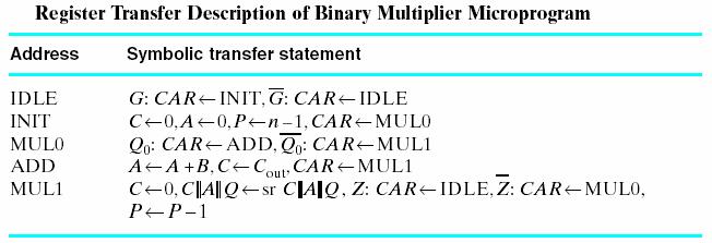
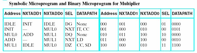
55 Microprogram 55
8-1. Fig. 8-1 ASM Chart Elements 2001 Prentice Hall, Inc. M. Morris Mano & Charles R. Kime LOGIC AND COMPUTER DESIGN FUNDAMENTALS, 2e, Updated.
 8-1 Name Binary code IDLE 000 Register operation or output R 0 RUN 0 1 Condition (a) State box (b) Example of state box (c) Decision box IDLE R 0 From decision box 0 1 START Register operation or output
8-1. Fig. 8-1 ASM Chart Elements 2001 Prentice Hall, Inc. M. Morris Mano & Charles R. Kime LOGIC AND COMPUTER DESIGN FUNDAMENTALS, 2e, Updated.
 8-1 Name Binary code IDLE 000 Register operation or output R 0 RUN Condition (a) State box (b) Example of state box (c) Decision box IDLE R 0 From decision box START Register operation or output PC 0 (d)
TABLE 8-1. Control Signals for Binary Multiplier. Load. MUL0 Q 0 CAQ sr CAQ. Shift_dec. C out. Load LOADQ. CAQ sr CAQ. Shift_dec P P 1.
 T-192 Control Signals for Binary Multiplier TABLE 8-1 Control Signals for Binary Multiplier Block Diagram Module Microoperation Control Signal Name Control Expression Register A: A 0 Initialize IDLE G
Sequential Logic - Module 5
 Sequential Logic Module 5 Jim Duckworth, WPI 1 Latches and Flip-Flops Implemented by using signals in IF statements that are not completely specified Necessary latches or registers are inferred by the
Contents. Chapter 9 Datapaths Page 1 of 28
 Chapter 9 Datapaths Page of 2 Contents Contents... 9 Datapaths... 2 9. General Datapath... 3 9.2 Using a General Datapath... 5 9.3 Timing Issues... 7 9.4 A More Complex General Datapath... 9 9.5 VHDL for
Control and Datapath 8
 Control and Datapath 8 Engineering attempts to develop design methods that break a problem up into separate steps to simplify the design and increase the likelihood of a correct solution. Digital system
EECE 353: Digital Systems Design Lecture 10: Datapath Circuits
 EECE 353: Digital Systems Design Lecture 10: Datapath Circuits Cristian Grecu grecuc@ece.ubc.ca Course web site: http://courses.ece.ubc.ca/353 Introduction to lecture 10 Large digital systems are more
ELCT 501: Digital System Design
 ELCT 501: Digital System Lecture 4: CAD tools (Continued) Dr. Mohamed Abd El Ghany, Basic VHDL Concept Via an Example Problem: write VHDL code for 1-bit adder 4-bit adder 2 1-bit adder Inputs: A (1 bit)
3 Designing Digital Systems with Algorithmic State Machine Charts
 3 Designing with Algorithmic State Machine Charts An ASM chart is a method of describing the sequential operations of a digital system which has to implement an algorithm. An algorithm is a well defined
[VARIABLE declaration] BEGIN. sequential statements
![[VARIABLE declaration] BEGIN. sequential statements](/thumbs/89/98890993.jpg "[VARIABLE declaration] BEGIN. sequential statements") PROCESS statement (contains sequential statements) Simple signal assignment statement
PROCESS statement (contains sequential statements) Simple signal assignment statement
Arithmetic Circuits. Nurul Hazlina Adder 2. Multiplier 3. Arithmetic Logic Unit (ALU) 4. HDL for Arithmetic Circuit
 4. HDL for Arithmetic Circuit") Nurul Hazlina 1 1. Adder 2. Multiplier 3. Arithmetic Logic Unit (ALU) 4. HDL for Arithmetic Circuit Nurul Hazlina 2 Introduction 1. Digital circuits are frequently used for arithmetic operations 2. Fundamental
Nurul Hazlina 1 1. Adder 2. Multiplier 3. Arithmetic Logic Unit (ALU) 4. HDL for Arithmetic Circuit Nurul Hazlina 2 Introduction 1. Digital circuits are frequently used for arithmetic operations 2. Fundamental
CSE 260 Introduction to Digital Logic and Computer Design. Exam 1. Your name 2/13/2014
 CSE 260 Introduction to Digital Logic and Computer Design Jonathan Turner Exam 1 Your name 2/13/2014 1. (10 points) Draw a logic diagram that implements the expression A(B+C)(C +D)(B+D ) directly (do not
Lecture 12 VHDL Synthesis
 CPE 487: Digital System Design Spring 2018 Lecture 12 VHDL Synthesis Bryan Ackland Department of Electrical and Computer Engineering Stevens Institute of Technology Hoboken, NJ 07030 1 What is Synthesis?
CS/EE Homework 7 Solutions
 CS/EE 260 - Homework 7 Solutions 4/2/2001 1. (20 points) A 4 bit twisted ring counter is a sequential circuit which produces the following sequence of output values: 0000, 1000, 1100, 1110, 1111, 0111,
Timing in synchronous systems
 BO 1 esign of sequential logic Outline Timing in synchronous networks Synchronous processes in VHL VHL-code that introduces latches andf flip-flops Initialization of registers Mealy- and Moore machines
The University of Alabama in Huntsville Electrical and Computer Engineering CPE/EE 422/522 Spring 2005 Homework #6 Solution
 5.3(a)(2), 5.6(c)(2), 5.2(2), 8.2(2), 8.8(2) The University of Alabama in Huntsville Electrical and Computer Engineering CPE/EE 422/522 Spring 25 Homework #6 Solution 5.3 (a) For the following SM chart:
VHDL in 1h. Martin Schöberl
 VHDL in 1h Martin Schöberl VHDL /= C, Java, Think in hardware All constructs run concurrent Different from software programming Forget the simulation explanation VHDL is complex We use only a small subset
Digital Design with SystemVerilog
 Digital Design with SystemVerilog Prof. Stephen A. Edwards Columbia University Spring 25 Synchronous Digital Design Combinational Logic Sequential Logic Summary of Modeling Styles Testbenches Why HDLs?
Hardware Description Language VHDL (1) Introduction
 Introduction") Hardware Description Language VHDL (1) Introduction Digital Radiation Measurement and Spectroscopy NE/RHP 537 Introduction Hardware description language (HDL) Intended to describe circuits textually, for
Hardware Description Language VHDL (1) Introduction Digital Radiation Measurement and Spectroscopy NE/RHP 537 Introduction Hardware description language (HDL) Intended to describe circuits textually, for
Abi Farsoni, Department of Nuclear Engineering and Radiation Health Physics, Oregon State University
 Hardware description language (HDL) Intended to describe circuits textually, for a computer to read Evolved starting in the 1970s and 1980s Popular languages today include: VHDL Defined in 1980s by U.S.
DIGITAL LOGIC DESIGN VHDL Coding for FPGAs Unit 6
 DIGITAL LOGIC DESIGN VHDL Coding for FPGAs Unit 6 FINITE STATE MACHINES (FSMs) Moore Machines Mealy Machines Algorithmic State Machine (ASM) charts FINITE STATE MACHINES (FSMs) Classification: Moore Machine:
Design Example: 4-bit Multiplier
 Design Example: 4-bit Multiplier Consider how we normally multiply numbers: 123 x 264 492 7380 24600 32472 Binary multiplication is similar. (Note that the product of two 4-bit numbers is potentially an
The University of Alabama in Huntsville ECE Department CPE Final Exam Solution Spring 2004
 The University of Alabama in Huntsville ECE Department CPE 526 01 Final Exam Solution Spring 2004 1. (15 points) An old Thunderbird car has three left and three right tail lights, which flash in unique
CprE 583 Reconfigurable Computing
 Recap 4:1 Multiplexer CprE / ComS 583 Reconfigurable Computing Prof. Joseph Zambreno Department of Electrical and Computer Engineering Iowa State University Lecture #18 VHDL for Synthesis I LIBRARY ieee
ECE 545 Lecture 12. Datapath vs. Controller. Structure of a Typical Digital System Data Inputs. Required reading. Design of Controllers
 ECE 545 Lecture 12 Design of Controllers Finite State Machines and Algorithmic State Machine (ASM) Charts Required reading P. Chu, using VHDL Chapter 1, Finite State Machine: Principle & Practice Chapter
VHDL. VHDL History. Why VHDL? Introduction to Structured VLSI Design. Very High Speed Integrated Circuit (VHSIC) Hardware Description Language
 Hardware Description Language") VHDL Introduction to Structured VLSI Design VHDL I Very High Speed Integrated Circuit (VHSIC) Hardware Description Language Joachim Rodrigues A Technology Independent, Standard Hardware description Language
VHDL Introduction to Structured VLSI Design VHDL I Very High Speed Integrated Circuit (VHSIC) Hardware Description Language Joachim Rodrigues A Technology Independent, Standard Hardware description Language
IT T35 Digital system desigm y - ii /s - iii
 UNIT - V Introduction to Verilog Hardware Description Language Introduction HDL for combinational circuits Sequential circuits Registers and counters HDL description for binary multiplier. 5.1 INTRODUCTION
DESCRIPTION OF DIGITAL CIRCUITS USING VHDL
 DESCRIPTION OF DIGITAL CIRCUITS USING VHDL Combinatinal circuits Sequential circuits Design organization. Generic design Iterative operations Authors: Luis Entrena Arrontes, Celia López, Mario García,
Modeling Complex Behavior
 Modeling Complex Behavior Sudhakar Yalamanchili, Georgia Institute of Technology, 2006 (1) Outline Abstraction and the Process Statement Concurrent processes and CSAs Process event behavior and signals
ECE 545 Lecture 12. FPGA Resources. George Mason University
 ECE 545 Lecture 2 FPGA Resources George Mason University Recommended reading 7 Series FPGAs Configurable Logic Block: User Guide Overview Functional Details 2 What is an FPGA? Configurable Logic Blocks
VHDL Examples Mohamed Zaky
 VHDL Examples By Mohamed Zaky (mz_rasmy@yahoo.co.uk) 1 Half Adder The Half Adder simply adds 2 input bits, to produce a sum & carry output. Here we want to add A + B to produce Sum (S) and carry (C). A
Two HDLs used today VHDL. Why VHDL? Introduction to Structured VLSI Design
 Two HDLs used today Introduction to Structured VLSI Design VHDL I VHDL and Verilog Syntax and ``appearance'' of the two languages are very different Capabilities and scopes are quite similar Both are industrial
COVER SHEET: Total: Regrade Info: 5 (14 points) 7 (15 points) Midterm 1 Spring 2012 VERSION 1 UFID:
 7 (15 points) Midterm 1 Spring 2012 VERSION 1 UFID:") EEL 4712 Midterm 1 Spring 2012 VERSION 1 Name: UFID: IMPORTANT: Please be neat and write (or draw) carefully. If we cannot read it with a reasonable effort, it is assumed wrong. As always, the best answer
EEL 4712 Midterm 1 Spring 2012 VERSION 1 Name: UFID: IMPORTANT: Please be neat and write (or draw) carefully. If we cannot read it with a reasonable effort, it is assumed wrong. As always, the best answer
Addition and multiplication
 Addition and multiplication Arithmetic is the most basic thing you can do with a computer, but it s not as easy as you might expect! These next few lectures focus on addition, subtraction, multiplication
Tailoring the 32-Bit ALU to MIPS
 Tailoring the 32-Bit ALU to MIPS MIPS ALU extensions Overflow detection: Carry into MSB XOR Carry out of MSB Branch instructions Shift instructions Slt instruction Immediate instructions ALU performance
Summary of FPGA & VHDL
 FYS4220/9220 Summary of FPGA & VHDL Lecture #6 Jan Kenneth Bekkeng, University of Oslo - Department of Physics 16.11.2011 Curriculum (VHDL & FPGA part) Curriculum (Syllabus) defined by: Lectures Lecture6:
Lab 3: Standard Combinational Components
 Lab 3: Standard Combinational Components Purpose In this lab you will implement several combinational circuits on the DE1 development board to test and verify their operations. Introduction Using a high-level
1. What is y-chart? ans: The y- chart consists of three domains:- behavioral, structural and geometrical.
 SECTION- A Short questions: (each 2 marks) 1. What is y-chart? ans: The y- chart consists of three domains:- behavioral, structural and geometrical. 2. What is fabrication? ans: It is the process used
ECE 545 Lecture 8. Data Flow Description of Combinational-Circuit Building Blocks. George Mason University
 ECE 545 Lecture 8 Data Flow Description of Combinational-Circuit Building Blocks George Mason University Required reading P. Chu, RTL Hardware Design using VHDL Chapter 7, Combinational Circuit Design:
EEL 4712 Digital Design Test 1 Spring Semester 2007
 IMPORTANT: Please be neat and write (or draw) carefully. If we cannot read it with a reasonable effort, it is assumed wrong. COVER SHEET: Problem: Points: 1 (15 pts) 2 (20 pts) Total 3 (15 pts) 4 (18 pts)
Lecture 7. Standard ICs FPGA (Field Programmable Gate Array) VHDL (Very-high-speed integrated circuits. Hardware Description Language)
 VHDL (Very-high-speed integrated circuits. Hardware Description Language)") Standard ICs FPGA (Field Programmable Gate Array) VHDL (Very-high-speed integrated circuits Hardware Description Language) 1 Standard ICs PLD: Programmable Logic Device CPLD: Complex PLD FPGA: Field Programmable
Standard ICs FPGA (Field Programmable Gate Array) VHDL (Very-high-speed integrated circuits Hardware Description Language) 1 Standard ICs PLD: Programmable Logic Device CPLD: Complex PLD FPGA: Field Programmable
Multiplication Simple Gradeschool Algorithm for 16 Bits (32 Bit Result)
") Multiplication Simple Gradeschool Algorithm for 16 Bits (32 Bit Result) Input Input Multiplier Multiplicand AND gates 16 Bit Adder 32 Bit Product Register Multiplication Simple Gradeschool Algorithm for
Multiplication Simple Gradeschool Algorithm for 16 Bits (32 Bit Result) Input Input Multiplier Multiplicand AND gates 16 Bit Adder 32 Bit Product Register Multiplication Simple Gradeschool Algorithm for
VHDL simulation and synthesis
 VHDL simulation and synthesis How we treat VHDL in this course You will not become an expert in VHDL after taking this course The goal is that you should learn how VHDL can be used for simulation and synthesis
EL 310 Hardware Description Languages Midterm
 EL 3 Hardware Description Languages Midterm 2 3 4 5 Total Name: ID : Notes: ) Please answer the questions in the provided space after each question. 2) Duration is minutes 3) Closed books and closed notes.
ECE 448 Lecture 3. Combinational-Circuit Building Blocks. Data Flow Modeling of Combinational Logic
 ECE 448 Lecture 3 Combinational-Circuit Building Blocks Data Flow Modeling of Combinational Logic George Mason University Reading Required P. Chu, FPGA Prototyping by VHDL Examples Chapter 3, RT-level
Chapter 6 Combinational-Circuit Building Blocks
 Chapter 6 Combinational-Circuit Building Blocks Commonly used combinational building blocks in design of large circuits: Multiplexers Decoders Encoders Comparators Arithmetic circuits Multiplexers A multiplexer
ECE260: Fundamentals of Computer Engineering
 Datapath for a Simplified Processor James Moscola Dept. of Engineering & Computer Science York College of Pennsylvania Based on Computer Organization and Design, 5th Edition by Patterson & Hennessy Introduction
ECOM 4311 Digital Systems Design
 ECOM 4311 Digital Systems Design Eng. Monther Abusultan Computer Engineering Dept. Islamic University of Gaza Page 1 Agenda 1. Counters Page 2 Counters - special name of any clocked sequential circuit
Lecture 5: State Machines, Arrays, Loops. EE 3610 Digital Systems
 EE 3610: Digital Systems 1 Lecture 5: State Machines, Arrays, Loops BCD to Excess-3 (XS 3 ) Code Converter Example: Fig. 2-53 2 Easier to use one type of code (e.g. XS 3 ) over the other type (e.g. BCD)
Sign here to give permission for your test to be returned in class, where others might see your score:
 EEL 4712 Midterm 2 Spring 216 VERSION 1 Name: UFID: Sign here to give permission for your test to be returned in class, where others might see your score: IMPORTANT: Please be neat and write (or draw)
Introduction to VHDL #3
 ECE 322 Digital Design with VHDL Introduction to VHDL #3 Lecture 7 & 8 VHDL Modeling Styles VHDL Modeling Styles Dataflow Concurrent statements Structural Components and interconnects Behavioral (sequential)
VHDL Modeling Behavior from Synthesis Perspective -Part B - EL 310 Erkay Savaş Sabancı University
 VHDL Modeling Behavior from Synthesis Perspective -Part B - EL 310 Erkay Savaş Sabancı University 1 The Wait Statement Syntax wait until condition; Different forms wait until(clk event and clk = 1 ); wait
EE 109L Review. Name: Solutions
 EE 9L Review Name: Solutions Closed Book / Score:. Short Answer (6 pts.) a. Storing temporary values in (memory / registers) is preferred due to the (increased / decreased) access time. b. True / False:
ECEU530. Schedule. ECE U530 Digital Hardware Synthesis. Datapath for the Calculator (HW 5) HW 5 Datapath Entity
 HW 5 Datapath Entity") ECE U530 Digital Hardware Synthesis Prof. Miriam Leeser mel@coe.neu.edu November 6, 2006 Classes November 6 and 8 are in 429 Dana! Lecture 15: Homework 5: Datapath How to write a testbench for synchronous
ECE U530 Digital Hardware Synthesis Prof. Miriam Leeser mel@coe.neu.edu November 6, 2006 Classes November 6 and 8 are in 429 Dana! Lecture 15: Homework 5: Datapath How to write a testbench for synchronous
Concurrent & Sequential Stmts. (Review)
") VHDL Introduction, Part II Figures in this lecture are from: Rapid Prototyping of Digital Systems, Second Edition James O. Hamblen & Michael D. Furman, Kluwer Academic Publishers, 2001, ISBN 0-7923-7439-
VHDL Introduction, Part II Figures in this lecture are from: Rapid Prototyping of Digital Systems, Second Edition James O. Hamblen & Michael D. Furman, Kluwer Academic Publishers, 2001, ISBN 0-7923-7439-
The VHDL Hardware Description Language
 The VHDL Hardware Description Language p. 1/? The VHDL Hardware Description Language CSEE W4840 Prof. Stephen A. Edwards Columbia University The VHDL Hardware Description Language p. 2/? Why HDLs? 1970s:
ACS College of Engineering. Department of Biomedical Engineering. Logic Design Lab pre lab questions ( ) Cycle-1
 Cycle-1") ACS College of Engineering Department of Biomedical Engineering Logic Design Lab pre lab questions (2015-2016) Cycle-1 1. What is a combinational circuit? 2. What are the various methods of simplifying
ACS College of Engineering Department of Biomedical Engineering Logic Design Lab pre lab questions (2015-2016) Cycle-1 1. What is a combinational circuit? 2. What are the various methods of simplifying
VHDL 2 Combinational Logic Circuits. Reference: Roth/John Text: Chapter 2
 VHDL 2 Combinational Logic Circuits Reference: Roth/John Text: Chapter 2 Combinational logic -- Behavior can be specified as concurrent signal assignments -- These model concurrent operation of hardware
Problem Set 10 Solutions
 CSE 260 Digital Computers: Organization and Logical Design Problem Set 10 Solutions Jon Turner thru 6.20 1. The diagram below shows a memory array containing 32 words of 2 bits each. Label each memory
Field Programmable Gate Array
 Field Programmable Gate Array System Arch 27 (Fire Tom Wada) What is FPGA? System Arch 27 (Fire Tom Wada) 2 FPGA Programmable (= reconfigurable) Digital System Component Basic components Combinational
VHDL And Synthesis Review
 VHDL And Synthesis Review VHDL In Detail Things that we will look at: Port and Types Arithmetic Operators Design styles for Synthesis VHDL Ports Four Different Types of Ports in: signal values are read-only
Sequential Statement
 Sequential Statement Sequential Logic Output depends not only on current input values but also on previous input values. Are building blocks of; Counters Shift registers Memories Flip flops are basic sequential
COVER SHEET: Total: Regrade Info: Problem#: Points. 7 (14 points) 6 (7 points) 9 (6 points) 10 (21 points) 11 (4 points)
 6 (7 points) 9 (6 points) 10 (21 points) 11 (4 points)") EEL 4712 Midterm 3 Spring 2013 VERSION 1 Name: UFID: Sign your name here if you would like for your test to be returned in class: IMPORTANT: Please be neat and write (or draw) carefully. If we cannot read
EEL 4712 Midterm 3 Spring 2013 VERSION 1 Name: UFID: Sign your name here if you would like for your test to be returned in class: IMPORTANT: Please be neat and write (or draw) carefully. If we cannot read
FPGA Design Challenge :Techkriti 14 Digital Design using Verilog Part 1
 FPGA Design Challenge :Techkriti 14 Digital Design using Verilog Part 1 Anurag Dwivedi Digital Design : Bottom Up Approach Basic Block - Gates Digital Design : Bottom Up Approach Gates -> Flip Flops Digital
VHDL: RTL Synthesis Basics. 1 of 59
 VHDL: RTL Synthesis Basics 1 of 59 Goals To learn the basics of RTL synthesis. To be able to synthesize a digital system, given its VHDL model. To be able to relate VHDL code to its synthesized output.
EE 459/500 HDL Based Digital Design with Programmable Logic. Lecture 6 Combinational and sequential circuits
 EE 459/5 HL Based igital esign with Programmable Logic Lecture 6 ombinational and sequential circuits Read before class: hapter 2 from textbook Overview ombinational circuits Multiplexer, decoders, encoders,
Multi-valued Logic. Standard Logic IEEE 1164 Type std_ulogic is ( U, uninitialized
 Multi-valued Logic Standard Logic IEEE 1164 Type std_ulogic is ( U, uninitialized X, unknown 0, logic 0 1, logic 1 Z, high impedance W, unknown L, logic 0 weak H, logic 1 weak - ); don t care Standard
DIGITAL LOGIC WITH VHDL (Fall 2013) Unit 6
 Unit 6") DIGITAL LOGIC WITH VHDL (Fall 2013) Unit 6 FINITE STATE MACHINES (FSMs) Moore Machines Mealy Machines FINITE STATE MACHINES (FSMs) Classification: Moore Machine: Outputs depend only on the current state
DIGITAL LOGIC WITH VHDL (Fall 2013) Unit 6 FINITE STATE MACHINES (FSMs) Moore Machines Mealy Machines FINITE STATE MACHINES (FSMs) Classification: Moore Machine: Outputs depend only on the current state
CMPT 250: Computer Architecture. Using LogicWorks 5. Tutorial Part 1. Somsubhra Sharangi
 CMPT 250: Computer Architecture Using LogicWorks 5 Tutorial Part 1 Somsubhra Sharangi What is VHDL? A high level language to describe digital circuit Different that a programming language ( such as Java)
Midterm Exam ECE 448 Spring 2014 Monday, March 3 (15 points)
") ECE8 Midterm Midterm Exam ECE 8 Spring 2 Monday, March 3 (5 points) Instructions: Zip all your delierables into an archie .zip and submit it through lackboard no later than Monday, March 3,
ECE8 Midterm Midterm Exam ECE 8 Spring 2 Monday, March 3 (5 points) Instructions: Zip all your delierables into an archie .zip and submit it through lackboard no later than Monday, March 3,
Part 4: VHDL for sequential circuits. Introduction to Modeling and Verification of Digital Systems. Memory elements. Sequential circuits
 M1 Informatique / MOSIG Introduction to Modeling and erification of Digital Systems Part 4: HDL for sequential circuits Laurence PIERRE http://users-tima.imag.fr/amfors/lpierre/m1arc 2017/2018 81 Sequential
Writing VHDL for RTL Synthesis
 Writing VHDL for RTL Synthesis Stephen A. Edwards, Columbia University December 21, 2009 The name VHDL is representative of the language itself: it is a two-level acronym that stands for VHSIC Hardware
COMP 303 Computer Architecture Lecture 6
 COMP 303 Computer Architecture Lecture 6 MULTIPLY (unsigned) Paper and pencil example (unsigned): Multiplicand 1000 = 8 Multiplier x 1001 = 9 1000 0000 0000 1000 Product 01001000 = 72 n bits x n bits =
REGISTER TRANSFER LANGUAGE
 REGISTER TRANSFER LANGUAGE The operations executed on the data stored in the registers are called micro operations. Classifications of micro operations Register transfer micro operations Arithmetic micro
EE 459/500 HDL Based Digital Design with Programmable Logic. Lecture 13 Control and Sequencing: Hardwired and Microprogrammed Control
 EE 459/500 HDL Based Digital Desig with Programmable Logic Lecture 13 Cotrol ad Sequecig: Hardwired ad Microprogrammed Cotrol Refereces: Chapter s 4,5 from textbook Chapter 7 of M.M. Mao ad C.R. Kime,
Hardware Description Languages. Modeling Complex Systems
 Hardware Description Languages Modeling Complex Systems 1 Outline (Raising the Abstraction Level) The Process Statement if-then, if-then-else, if-then-elsif, case, while, for Sensitivity list Signals vs.
Computer Architecture Programming the Basic Computer
 4. The Execution of the EXCHANGE Instruction The EXCHANGE routine reads the operand from the effective address and places it in DR. The contents of DR and AC are interchanged in the third microinstruction.
Lab 3. Advanced VHDL
 Lab 3 Advanced VHDL Lab 3 Advanced VHDL This lab will demonstrate many advanced VHDL techniques and how they can be used to your advantage to create efficient VHDL code. Topics include operator balancing,
CprE 583 Reconfigurable Computing
 Recap Moore FSM Example CprE / ComS 583 Reconfigurable Computing Moore FSM that recognizes sequence 10 0 1 0 1 S0 / 0 S1 / 0 1 S2 / 1 Prof. Joseph Zambreno Department of Electrical and Computer Engineering
EITF35: Introduction to Structured VLSI Design
 EITF35: Introduction to Structured VLSI Design Part 1.2.2: VHDL-1 Liang Liu liang.liu@eit.lth.se 1 Outline VHDL Background Basic VHDL Component An example FSM Design with VHDL Simulation & TestBench 2
Mark Redekopp, All rights reserved. EE 352 Unit 8. HW Constructs
 EE 352 Unit 8 HW Constructs Logic Circuits Combinational logic Perform a specific function (mapping of 2 n input combinations to desired output combinations) No internal state or feedback Given a set of
Inferring Storage Elements
 Inferring Storage Elements In our designs, we usually use flip-flops as our storage elements. Sometimes we use latches, but not often. Latches are smaller in size, but create special, often difficult situations
The University of Alabama in Huntsville ECE Department CPE Midterm Exam Solution Spring 2016
 The University of Alabama in Huntsville ECE Department CPE 526 01 Midterm Exam Solution Spring 2016 1. (15 points) Write a VHDL function that accepts a std_logic_vector of arbitrary length and an integer
CSE 260 Introduction to Digital Logic and Computer Design. Exam 1 Solutions
 CSE 6 Introduction to igital Logic and Computer esign Exam Solutions Jonathan Turner /3/4. ( points) raw a logic diagram that implements the expression (B+C)(C +)(B+ ) directly (do not simplify first),
Digital System Design Using Verilog. - Processing Unit Design
 Digital System Design Using Verilog - Processing Unit Design 1.1 CPU BASICS A typical CPU has three major components: (1) Register set, (2) Arithmetic logic unit (ALU), and (3) Control unit (CU) The register
6.1 Combinational Circuits. George Boole ( ) Claude Shannon ( )
 Claude Shannon ( )") 6. Combinational Circuits George Boole (85 864) Claude Shannon (96 2) Signals and Wires Digital signals Binary (or logical ) values: or, on or off, high or low voltage Wires. Propagate digital signals
6. Combinational Circuits George Boole (85 864) Claude Shannon (96 2) Signals and Wires Digital signals Binary (or logical ) values: or, on or off, high or low voltage Wires. Propagate digital signals
RTL Design (Using ASM/SM Chart)
") Digital Circuit Design and Language RTL Design (Using ASM/SM Chart) Chang, Ik Joon Kyunghee University Process of Logic Simulation and Synthesis Design Entry HDL Description Logic Simulation Functional
Digital Circuit Design and Language RTL Design (Using ASM/SM Chart) Chang, Ik Joon Kyunghee University Process of Logic Simulation and Synthesis Design Entry HDL Description Logic Simulation Functional
Luleå University of Technology Kurskod SMD152 Datum Skrivtid
 Luleå University of Technology Kurskod SMD152 Datum 2003-10-24 Skrivtid 9.00 13.00 1 Manual synthesis (10 p, 2 p each) Here you are given five different VHDL models. Your task is to draw the schematics
Design Examples. ELEC 418 Advanced Digital Systems Dr. Ron Hayne. Images Courtesy of Cengage Learning
 Design Examples ELEC 418 Advanced Digital Systems Dr. Ron Hayne Images Courtesy of Cengage Learning BCD to 7-Segment Display 418_04 2 BCD to 7-Segment Display entity BCD_Seven is port(bcd: in std_logic_vector(3
VHDL Testbench. Test Bench Syntax. VHDL Testbench Tutorial 1. Contents
 VHDL Testbench Tutorial 1 Contents 1 VHDL Testbench 2 Test Bench Syntax 3 Testbench Example: VHDL Code for Up Down Binary Counter 4 VHDL Testbench code for up down binary counter 5 Testbench Waveform for
Using Library Modules in VHDL Designs
 Using Library Modules in VHDL Designs This tutorial explains how Altera s library modules can be included in VHDL-based designs, which are implemented by using the Quartus R II software. Contents: Example
DIGITAL LOGIC WITH VHDL (Fall 2013) Unit 3
 Unit 3") DIGITAL LOGIC WITH VHDL (Fall 2013) Unit 3 BEHAVIORAL DESCRIPTION Asynchronous processes (decoder, mux, encoder, etc): if-else, case, for-loop. BEHAVIORAL DESCRIPTION (OR SEQUENTIAL) In this design style,
DIGITAL LOGIC WITH VHDL (Fall 2013) Unit 3 BEHAVIORAL DESCRIPTION Asynchronous processes (decoder, mux, encoder, etc): if-else, case, for-loop. BEHAVIORAL DESCRIPTION (OR SEQUENTIAL) In this design style,
Cpr E 281 FINAL PROJECT ELECTRICAL AND COMPUTER ENGINEERING IOWA STATE UNIVERSITY. FINAL Project. Objectives. Project Selection
 Objectives The main objective of the final project is to teach you how to put together all of the class material that you have learned so far in order to program the Altera DE2 board to carry out an independent
Outline. CPE/EE 422/522 Advanced Logic Design L05. Review: General Model of Moore Sequential Machine. Review: Mealy Sequential Networks.
 Outline CPE/EE 422/522 Advanced Logic Design L05 Electrical and Computer Engineering University of Alabama in Huntsville What we know Combinational Networks Sequential Networks: Basic Building Blocks,
Spiral 1 / Unit 6. Flip-flops and Registers
 1-5.1 Spiral 1 / Unit 6 Flip-flops and Registers 1-5.2 Outcomes I know the difference between combinational and sequential logic and can name examples of each. I understand latency, throughput, and at
Using Library Modules in VHDL Designs
 Using Library Modules in VHDL Designs This tutorial explains how Altera s library modules can be included in VHDL-based designs, which are implemented by using the Quartus R II software. Contents: Example
Schedule. ECE U530 Digital Hardware Synthesis. Rest of Semester. Midterm Question 1a
 ECE U530 Digital Hardware Synthesis Prof. Miriam Leeser mel@coe.neu.edu November 8, 2006 Midterm Average: 70 Lecture 16: Midterm Solutions Homework 6: Calculator Handshaking HW 6: Due Wednesday, November
EEL 4712 Digital Design Test 1 Spring Semester 2008
 IMPORTANT: Please be neat and write (or draw) carefully. If we cannot read it with a reasonable effort, it is assumed wrong. Also, as always, the best answer gets the most points. COVER SHEET: Problem:
Outcomes. Spiral 1 / Unit 6. Flip Flops FLIP FLOPS AND REGISTERS. Flip flops and Registers. Outputs only change once per clock period
 1-5.1 1-5.2 Spiral 1 / Unit 6 Flip flops and Registers Mark Redekopp Outcomes I know the difference between combinational and sequential logic and can name examples of each. I understand latency, throughput,