Computer Graphics
|
|
|
- Samuel Parsons
- 5 years ago
- Views:
Transcription
1 Computer Graphics Chapter 10 llumination Models and Surface-Rendering Methods Somsak Walairacht, Computer Engineering, KMTL 1
2 Outline Light Sources Surface Lighting Effects Basic llumination Models Polygon Rendering Methods Texture Mapping Ray-Tracing Radiosity 2
3 llumination Model Lighting model or Shading model Calculate the color of an illuminated positions on the surface of an object Ray-tracing Topics Light sources Basic models Lighting-surface effects 3
4 Surface-Rendering Method Shading Method Determine the pixel color using color calculations from an illumination model Scan-line, mage-space algorithms Topics Polygon rendering methods Ray-tracing Radiosity Texture Mapping 4

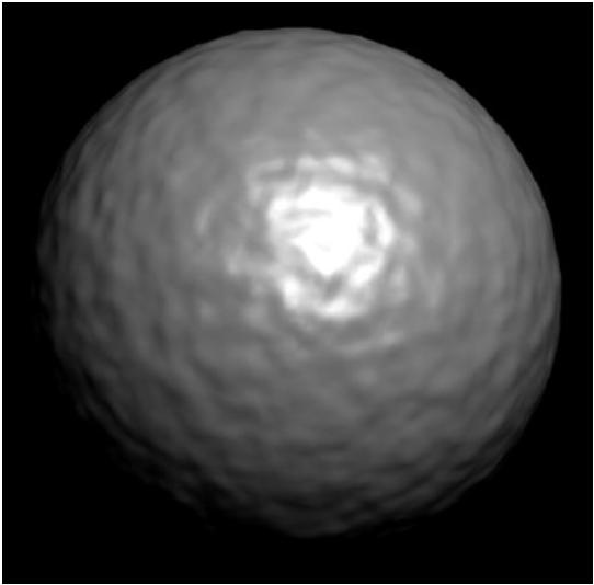
5 Why Lighting? f we don t have lighting effects nothing looks three dimensional 5
6 Photorealism in Computer Graphics Accurate representation of surface properties Good physical descriptions of light effects in the scene Reflections Refraction Transparency Surface texture Shadows 6
7 Light Sources 1) Point light Simplest, position and color 2) nfinite distant light Large source, the sun Constant distance to any positions Directional vector and color Radial intensity attenuation 3) Directional light Spotlight, cone beam Directional vector, angular limit, position, and color 4) Extended light Large source closed to object Light emitting surface 8
8 Point Light Sources A point source is the simplest model we can use for a light source Simply define The position of the light The RGB values for the colour of the light Light is emitted in all directions Useful for small light sources 9
9 Radial ntensity Attenuation As light moves from a light source its intensity diminished At any distance d l away from the light source the intensity diminishes by a 1 factor of 2 d l However, using this factor does not produce very good results so we use something different 10
10 Radial ntensity Attenuation An inverse quadratic function is used instead f radatten ( d l ) k c k l d 1 l k q d 2 l where d l = distance between the light and the surface being shaded k c = constant attenuation factor k l = linear attenuation factor k q = quadratic attenuation factor 11

11 Example f radatten ( d l ) 1 2 r d l 1 1 r 2 d 2 l 12
12 nfinite Distant Light Sources A large light source, like the sun, can be modelled as a point light source However, it will have very little directional effect Radial intensity attenuation is not used 13
13 Directional Light Sources To turn a point light source into a spotlight, simply add a vector direction and an angular limit θ l 14
14 Directional Light Sources & Spotlight Effects Denote V light as the unit vector in the direction of the light V obj as the unit vector from the light source to an object The dot-product of these two vectors gives us the angle between them V obj Vlight cos f this angle is inside the light s angular limit then the object is within the spotlight 15
 cos where a l the attenuation exponent, is assigned some positive value and angle is measured from the cone axis a")
15 Angular ntensity Attenuation As well as light intensity decreasing as we move away from a light source, it also decreases angularly A commonly used function for calculating angular attenuation is: fangatten ( ) cos where a l the attenuation exponent, is assigned some positive value and angle is measured from the cone axis a l 0 16
16 Extended Light Sources Approximate it as a light-emitting surface We can set the direction for the point sources Behind the lightemitting surface are not illuminated 17


17 Reflected Light The colors that we perceived are determined by the nature of the light reflected from an object For example, if white light is shone onto a green object most wavelengths are absorbed, while green light is reflected from the object Colors Absorbed 18
18 Surface Lighting Effects The amount of incident light reflected by a surface depends on the type of material Shiny materials reflect more of the incident light Dull surfaces absorb more of the incident light For transparent surfaces, some of the light is also transmitted through the material 19
19 Diffuse Reflection Surfaces that are rough or grainy tend to reflect light in all directions กระจาย This scattered light is called Diffuse Reflection 20
20 Specular Reflection Additionally to diffuse reflection some of the reflected light is concentrated into a highlight or bright spot เก ยวก บกระจกเงา This is called Specular Reflection 21
21 ความเข มของแสง Basic llumination Model We will consider a basic illumination model which gives reasonably good results and is used in most graphics systems การท าให ส องสว าง The important components are: Ambient light Diffuse reflection Specular reflection 22


22 Basic llumination Model Ambient Diffuse Specular Final mage 23
23 Ambient Light To incorporate background light we simply set a general brightness level for a scene ndependent of viewing direction and the spatial orientation of a surface Assuming only monochromatic light effects, we designate ambient light with the value a 24


24 Diffuse Reflection Assume that surfaces reflect incident light with equal intensity in all directions Such surfaces are referred to as deal Diffuse Reflectors or Lambertian Reflectors 25
25 Diffuse Reflection A parameter k d is set for each surface that determines the fraction of incident light that is to be scattered as diffuse reflections from that surface This parameter is known as the Diffuse- Reflection Coefficient or the Diffuse Reflectivity k d is assigned a value between 0.0 and : dull surface that absorbs almost all light 1.0: shiny surface that reflects almost all light 26
26 Diffuse Reflection Ambient Light For background lighting effects we can assume that every surface is fully illuminated by the ambient light a Therefore the ambient contribution to the diffuse reflection is given as: k ambdiff d a Ambient light alone is very uninteresting so we need some other lights in a scene as well 27
27 Diffuse Reflection Brightness depends on the orientation of a surface The amount of incident light on a surface is given as: cos l, incident l So we can model the diffuse reflections as: k l, diff k d d l, incident l cos 28
 if if N N L L 0 0")
28 Diffuse Reflection Assuming we denote the normal for a surface as N and the unit direction vector to the light source as L then: So, N L cos l, diff k d l ( N 0 L) if if N N L L
29 Combining Ambient And ncident Diffuse Reflections Most graphics packages use two separate diffuse-reflection coefficients: k a for ambient light k d for incident light The total diffuse reflection equation for a single point source can then be given as: diff k a a k k d a l a ( N L) if if N L N L

30 Combining Ambient And ncident Diffuse Reflections 31

31 Ambient Light k a a 32

32 Ambient and Diffuse Reflection k a a k d l ( N L) 33
33 Specular Reflection The bright spot on a shiny surface is the result of near total of the incident light in a concentrated region around the specular reflection angle The specular reflection angle equals the angle of the incident light 34
34 Specular Reflection A perfect mirror reflects light only in the specular-reflection direction Other objects exhibit specular reflections over a finite range of viewing positions around vector R 35
35 Effect of n shiny The effect of n s on the angular range in which we can expect to see specular reflections 36
36 The Phong Specular Reflection Model An empirical model for calculating specular reflection range Developed in 1973 by Phong Bui Tuong The intensity of specular reflection is set proportional to the angle between the viewing vector and the specular reflection vector 37
37 Phong Model The specular reflection intensity is proportional to cos n s The angle can be varied between 0 and 90 so that cos varies from 1.0 to 0.0 The Specular-Reflection Exponent, n s is determined by the type of surface we want to display Shiny surfaces have a very large value (>100) Rough surfaces would have a value near 1 38

38 Phong Model The specular reflection intensity is given as: n k cos s l, spec s l Since, V R cos l, spec k s l ( V 0.0 R) n s if if V V R R 0 and 0 or N N L L
N L More efficient, use Halfway vector H")
39 Phong Model Calculate of vector R R+L = (2LN)N R = (2LN)N L More efficient, use Halfway vector H 40
 s L V L V")
40 The Halfway Vector Blinn proposed an alternative to Phong's model that uses the halfway vector The halfway vector is the direction of maximum highlights f the surface is oriented so that the normal is aligned along, the viewer sees the brightest specular highlights f light source and viewer are far away, H ±constant l, spec H k ( N H ) s L V L V l n s 41

41 Blinn Phong Reflection Model Using halfway angle Set specular reflection exponent, n s close to the formal expression 42

42 Diffuse and Specular Constants k s The diffuse constant determines the intensity of the diffuse component Notice that the diffuse component gets brighter across the rows The specular constant determines the intensity of the specular component Notice that the specular component gets brighter up the columns k d 43
43 44 Combining Diffuse & Specular Reflections Effects of diffuse and specular reflections can be combined as For any number of light sources in a scene n s l s l d a a spec diff amb H N k L N k k ) ( ) ( n l n s d l a a n l spec l diff l amb s H N k L N k k 1 1,,
44 RGB Color Considerations For an RGB color description each intensity specification is a three element vector So, for each light source: l,, lr lg Similarly all parameters are given as vectors: a lb k, k k k k, k, k k, ar ag ab k k, k, k s sr d sg sb dr dg db 45
45 Total llumination k a l a k d l ( L N) 46
 k ( H s N) n s n s 5")
46 Total llumination k a a l k d ( L N) k ( H s N) n s n s 5 47
47 Total llumination k a a l k d ( L N) k ( H s N) n s n s 50 48
 k ( H s N) n s n s 500")
48 Total llumination k a a l k d ( L N) k ( H s N) n s n s
49 Single Light Source k a a l k d ( L N) k ( H s N) n s 50
50 Multiple Light Sources k a a i i k d ( L i N) k s ( H i N) n s 51
51 52 Attenuation Decrease intensity with distance from light d = distance to light r = radius of attenuation for light ), ( ) ) max(0,(1 ), ( ) max(0,1 ), ( ) max(0,1 ), ( 2 r d r d r d r d e r d att r d att r d att r d att
52 Attenuation k a a i i n s k L N ) k ( H N ) att( d, r ) d ( i s i i 53
53 Attenuation k a a i i k L N) k ( H N) ns att( d, r ) ( d i s i i 54
, cos( ), 0 L A L Surface")
54 Spot Lights Eliminate light contribution outside of a cone A spotcoeff L L A A cos( ), cos( ), 0 L A L Surface 55
55 Spot Lights k a a i i k ( L N) k ( H N) ns spotcoeff d i s i i 56
56 Spot Lights k a a i i k ( L N) k ( H N) ns spotcoeff d i s i i 57
 ns spotcoeff d i s i i 58")
57 Spot Lights k a a i i k ( L N) k ( H N) ns spotcoeff d i s i i 58
58 Transparency Snell s law of refraction: L N i i r R T sin T r i sini, :index of refraction r i i cosi cosr N L r r Derivation : Use Snell's law, T. T 1, T N cosr, T N L, and solve for and

59 No Surface Rendering VS Flat Surface Rendering No Surface Rendering Flat Surface Rendering 60

60 Flat Surface Rendering VS Gouraud Surface Rendering Flat Surface Rendering Gouraud Surface Rendering 61
61 Gouraud Surface Rendering VS Phong Surface Rendering Gouraud Surface Rendering Phong Surface Rendering 62

62 Flat Surface Rendering The simplest method for rendering a polygon surface The same colour is assigned to all surface positions The illumination at a single point on the surface is calculated and used for the entire surface Flat surface rendering is extremely fast, but can be unrealistic 63


63 Gouraud Surface Rendering Gouraud surface shading was developed in the 1970s by Henri Gouraud Worked at the University of Utah along with van Sutherland and David Evans Often also called intensityinterpolation surface rendering ntensity levels are calculated at each vertex and interpolated across the surface 64
64 Gouraud Surface Rendering (cont ) To render a polygon, Gouraud surface rendering proceeds as follows: 1. Determine the average unit normal vector at each vertex of the polygon 2. Apply an illumination model at each polygon vertex to obtain the light intensity at that position 3. Linearly interpolate the vertex intensities over the projected area of the polygon 65
65 Gouraud Surface Rendering (cont ) N 1 The average unit normal vector at v is given as: N 4 N v v N 2 N v N N 1 1 N N or more generally: 2 2 N N 3 3 N N 4 4 N 3 N v n i1 n i1 N N i i 66
66 67 Gouraud Surface Rendering (cont ) y y y y y y y y x y Scan-line p y y y y y y y y x x x x x x x x p p p llumination values are linearly interpolated across each scan-line
67 Advantages of Gouraud Surface Rendering 68
68 Gouraud Surface Rendering mplementation Gouraud surfacing rendering can be implemented relatively efficiently using an iterative approach Typically Grouaud shading is implemented as part of a visible surface detection technique 69


69 Problems with Gouraud Shading Gouraud shading tends to miss certain highlighting n particular Gouraud shading has a problem with specular reflections Also, Gouraud shading can introduce anomalies known as Machbands 70

70 Problems with Gouraud Shading (cont ) Gouraud shading Phong shading The major problem with Gouraud shading is in handling specular reflections 71
71 The Machband Effect A psychological phenomenon whereby we see bright bands where two blocks of solid color meet High light can get lost or grow Corners on silhouette remain Machband effect is visible at some edges A good demo is available to experiment with this at: s490-96to97/anson/machbandingapplet/ 72
72 Phong Shading ncremental normal vector update along and between scan lines Comparison to Gouraud shading Better highlights Less Machbanding More costly 73
73 Phong Surface Rendering A more accurate interpolation based approach for rendering a polygon was developed by Phong Bui Tuong Basically the Phong surface rendering model (or normal-vector interpolation rendering) interpolates normal vectors instead of intensity values 74
74 Phong Surface Rendering (cont ) To render a polygon, Phong surface rendering proceeds as follows: 1. Determine the average unit normal vector at each vertex of the polygon 2. Linearly interpolate the vertex normals over the projected area of the polygon 3. Apply an illumination model at positions along scan lines to calculate pixel intensities using the interpolated normal vectors 75
75 76 Phong Surface Rendering (cont ) N 4 N 1 N 2 N 3 Scan line N y y y y N y y y y N N N y y y y N y y y y N N p p N y y y y N y y y y N p p p

76 Phong Surface Rendering mplementation Phong shading is much slower than Gouraud shading as the lighting model is revaluated so many times Typically, Phong shading is implemented as part of a visible surface detection technique 77


77 Texture Mapping A way of adding surface details Two ways can achieve the goal: Surface detail polygons: create extra polygons to model object details Add scene complexity and thus slow down the graphics rendering speed Some fine features are hard to model! Map a texture to the surface (a more popular approach) Complexity of images does Not affect the complexity Of geometry processing (transformation, clipping )


78 Texture Mapping 1. projection 3. patch texel 3D geometry 2. texture lookup t 2D projection of 3D geometry 2D image S
79 Texture Representation Bitmap (pixel map) textures (supported by OpenGL) Procedural textures (used in advanced rendering programs) t (0,0) (1,1) s Bitmap texture: A 2D image - represented by 2D array texture[height][width] Each pixel (or called texel ) by a unique pair texture coordinate (s, t) The s and t are usually normalized to a [0,1] range For any given (s,t) in the normalized rang there is also a unique image value (i.e., a unique [red, green, blue] set )
80 Texture Value Lookup For given texture coordinates (s,t), we can find a unique image value from the texture map (1,1) How about coordinates that are not exactly at the intersection (pixel) position A) Nearest neighbor B) Linear nterpolation C) Other filters (0,0) (0.25,0)(0.5,0)(0.75,0) (1,0)
81 Map textures to surfaces Establish mapping from texture to surfaces (polygons): - Application program needs to specify texture coordinates for each corner of the polygon The polygon can be in an arbitrary size (1,0) (1,1) (0,0) (1,0)
82 Map textures to surfaces Texture mapping is performed in rasterization (0,1) (1,1) For each pixel that is to be painted, its texture coordinates (s, t) are determined (interpolated) based on the corners texture coordinates (why not just interpolate the color?) (0,0) (1,0) The interpolated texture coordinates are then used to perform texture lookup
83 OpenGL texture mapping Texturing steps in your program 1) Specify texture - read or generate image - Assign to texture 2) Specify texture mapping parameters - Wrapping, filtering, etc. 3) Enable GL texture mapping (GL_TEXTURE_2D) 4) Assign texture coordinates to vertices 5) Disable GL texture mapping (if you don t need to perform texture mapping any more)
84 Specify textures Load the texture map from main memory to texture memory gltexmage2d(glenum target, Glint level, Glint iformat, int width, int height, Glenum format, Glenum type, Glvoid* img) Example: glteximage2d(gl_texture_2d, 0, GL_RGB, 64, 64, GL_RGB, GL_UNSGNED_BYTE, mymage); (mymage is a 2D array: GLuByte mymage[64][64][3]; ) The dimensions of texture images must be powers of 2
 use gluscalemage() 100 60 64 128 Ask OpenGL to filter the data for you to the")

85 Fix texture size f the dimensions of the texture map are not power of 2, you can 1) Pad zeros 2) use gluscalemage() Ask OpenGL to filter the data for you to the right size you can specify the output resolution that you want Remember to adjust the texture coordinates for your polygon corners you don t want to nclude black texels in your final picture
86 Texture mapping parameters What happen if the given texture coordinates (s,t) are outside [0,1] range? (1,1) (2,2) (2,2) (0,0) texture (0,0) GL_Repeat E.g: gltexparameteri(gl_textaure_2d, GL_TEXTURE_WRAP_S, GL_CLAMP) (0,0) GL_Clamp f (s >1) s = 1 f (t >1) t = 1
87 Texture mapping parameters Since a polygon can get transformed to arbitrary screen size, texels in the texture map can get magnified or minified. texture polygon projection texture polygon projection Magnification Minification Filtering: interpolate a texel value from its neighbors or combine multiple texel values into a single one
88 Texture mapping parameters OpenGL texture filtering: 1) Nearest Neighbor (lower image quality) 2) Linear interpolate the neighbors (better quality, slower) gltexparameteri(gl_texture_2d, GL_TEXTURE_MN_FLTER, GL_NEAREST); gltexparameteri(gl_texture_2d, GL_TEXTURE_MN_FLTER, GL_LNEAR) Or GL_TEXTURE_MAX_FLTER
89 Texture color blending Determine how to combine the texel color and the object color GL_MODULATE multiply texture and object color GL_BLEND linear combination of texture and object color GL_REPLACE use texture color to replace object color E.g: gltexenvf(gl_texture_env, GL_TEXTURE_ENV_MODE, GL_REPLACE);
90 Enable (Disable) Textures Enable texture glenable(gl_texture_2d) Disable texture gldisable(gl_texture_2d) Remember to disable texture mapping when you draw non-textured polygons
91 Specify texture coordinates Give texture coordinates before defining each vertex glbegin(gl_quads); gltexcoord2f(0.0f, 0.0f); glvertex3f(-1.0f, -1.0f, 0.0f); gltexcoord2f(0.0f, 1.0f); glvertex3f(-1.0f, 1.0f, 0.0f); gltexcoord2f(1.0f, 0.0f); glvertex3f( 1.0f, 1.0f, 0.0f); gltexcoord2f(1.0f, 1.0f); glvertex3f( 1.0f, -1.0f, 0.0f); glend();
92 Transform texture coordinates All the texture coordinates are multiplied by GL_TEXTURE matrix before in use To transform texture coordinates, you do: glmatrixmode(gl_texture); Apply regular transformation functions Then you can draw the textured objects
93 Put it all together gltexparameteri(gl_texture_2d, GL_TEXTURE_WRAP_S, GL_REPEAT); gltexparameteri(gl_texture_2d, GL_TEXTURE_WRAP_T, GL_REPEAT); gltexparameteri(gl_texture_2d, GL_TEXTURE_MAG_FLTER, GL_NEAREST); gltexparameteri(gl_texture_2d, GL_TEXTURE_MN_FLTER, GL_NEAREST); gltexenvf(gl_texture_env, GL_TEXTURE_ENV_MODE, GL_REPLACE); glenable(gl_texture_2d); gltexmage2d(gl_texture_2d, 0, GL_RGB, 64, 64, 0, GL_RGB, GL_UNSGNED_BYTE, mytexture); Draw_picture1(); // define texture coordinates and vertices in the function
94 Other Stuff Wrapping texture onto curved surfaces. E.g. cylinder, can, etc Wrapping texture onto sphere Bump mapping: perturb surface normal by a quantity proportional to texture a b a s a b a z z z z t a b a s a b a t

95 Planar Map Shape Determine which component was projected by looking for color changes in coordinate directions When moving parallel to the x-axis, an object s color changes. When moving up and down along the y-axis, the object s color also changes. However, movement along the z-axis does not produce a change in color. 96


96 Cylinder Map Shape An (x,y,z) value is converted to cylindrical coordinates of ( r, theta, height ) theta is converted into x-coordinate height is converted into y-coordinate 97


97 Sphere Map Shape The (x,y,z) value of a point is converted into spherical coordinates The latitude is converted into an x-coordinate The longitude is converted into a y-coordinate 98


98 Box Map Shape Enclosing box is usually axis-parallel bounding box of object Six rectangles onto which the texture is mapped Similar to planar mapping 99

99 Bump Mapping Bump mapping affects object surfaces, making them appear rough, wrinkled, or dented Bump mapping alters the surface normals before the shading calculation takes place 100
100 Bump VS Displacement Mapping Bump Mapping Variation of surface normals Apply normal perturbation without updating positions Displacement Mapping Variation of surface positions, thus normal Requires fine tessellation of object geometry 101
101 102


102 Environment Mapping A two-dimensional texture mapping technique that uses a map shape of a box and a map parameter of a reflection ray it s easy to create reflections with a ray tracer, ray tracing is still too expensive for long animations 103

103 Ray-Tracing Provides rendering method with Refraction/Transparent surfaces Reflective surfaces Shadows mage taken from 104
104 Ray-Tracing: Principle View point Screen Primary ray Normal Reflected ray Shadow ray Refracted ray
105 Ray-Tracing: Principle Trace a primary ray passing through a pixel P : intersection point Compute the contribution of the sources to P by tracing shadow rays toward the light sources f a shadow ray intersects an opaque object between P and the light source then P is shadowed Compute the contribution to P of other points within the scene by tracing secondary rays: reflected and refracted A reflected ray is traced only if the material is specular A refracted ray is traced only if the material is transparent A secondary ray intersects the scene at a point P Again compute the contribution of the sources to P by tracing shadow rays toward the light sources. Repeat the process Each ray brings its contribution to the luminance of a point 106
106 Ray-Tracing: Pseudo code For each ray r from eye to pixel, color the pixel with the value returned by ray_cast(r, scene, depth) ray_cast(r, scene, depth) { f(depth > Max_Depth) { color black } else { f (intersection(r, scene)) { p point_of_intersection(r, scene); u reflect(r, p); v refract(r, p); color phong_direct(p, r) + ks ray_cast(u, scene, depth+1) + kt ray_cast(v, scene, depth+1); } else color background_color ; } return(color); } 107
107 Ray-Tracing: Pseudo code Explained p point_of_intersection(r, scene); Compute p, the point of intersection of ray r with the scene u reflect(r, p); v refract(r, p); Compute the reflected ray u and the refracted ray v using Snell s Laws phong(p, r) Evaluate the Phong reflection model for the ray r at point p on surface s, taking shadowing into account ks ray_cast(u,scene,depth) Multiply the contribution from the reflected ray u by the specular color ks for surface s containing p. Only (specular-to-specular) * light transport is handled. deal specular (mirror) reflection kt ray_cast(v,scene,depth) Multiply the contribution from the refracted ray v by the specular-refraction coefficient kt for surface s. Only (specular-refraction) * light transport is handled 108
108 Rays & Ray Tree Corresponding binary ray-tracing tree Primary-, Secondary-, Reflected-, Transmitted- Rays 109

109 Radiosity Light can be reflected between two objects that have diffuse surfaces This is commonly called color bleeding Radiosity treats light as energy llumination of the scene is the transfer of energy mage created by Erik Svanholm 2002 Zumtobel Staff 110

110 Radiosity Method Describe the physical process of light distribution in a diffuse reflecting environment Areas that are not illuminated directly are also not completely dark Every objects act as a secondary light source 111

111 Ray-Tracing VS Radiosity Ray-Tracing mage-space From Eye to Light Specular Reflection Radiosity Object-Space From Light to Surface Diffuse Reflection 112
112 End of Chapter
Chapter 10. Surface-Rendering Methods. Somsak Walairacht, Computer Engineering, KMITL
 Computer Graphics Chapter 10 llumination Models and Surface-Rendering Methods Somsak Walairacht, Computer Engineering, KMTL 1 Outline Light Sources Surface Lighting Effects Basic llumination Models Polygon
Computer Graphics. Illumination Models and Surface-Rendering Methods. Somsak Walairacht, Computer Engineering, KMITL
 Computer Graphics Chapter 10 llumination Models and Surface-Rendering Methods Somsak Walairacht, Computer Engineering, KMTL Outline Light Sources Surface Lighting Effects Basic llumination Models Polygon
Today we will start to look at illumination models in computer graphics
 1 llumination Today we will start to look at illumination models in computer graphics Why do we need illumination models? Different kinds lights Different kinds reflections Basic lighting model 2 Why Lighting?
Comp 410/510 Computer Graphics. Spring Shading
 Comp 410/510 Computer Graphics Spring 2017 Shading Why we need shading Suppose we build a model of a sphere using many polygons and then color it using a fixed color. We get something like But we rather
Graphics. Texture Mapping 고려대학교컴퓨터그래픽스연구실.
 Graphics Texture Mapping 고려대학교컴퓨터그래픽스연구실 3D Rendering Pipeline 3D Primitives 3D Modeling Coordinates Model Transformation 3D World Coordinates Lighting 3D World Coordinates Viewing Transformation 3D Viewing
Illumination & Shading
 Illumination & Shading Goals Introduce the types of light-material interactions Build a simple reflection model---the Phong model--- that can be used with real time graphics hardware Why we need Illumination
CPSC 314 LIGHTING AND SHADING
 CPSC 314 LIGHTING AND SHADING UGRAD.CS.UBC.CA/~CS314 slide credits: Mikhail Bessmeltsev et al 1 THE RENDERING PIPELINE Vertices and attributes Vertex Shader Modelview transform Per-vertex attributes Vertex
Lecture 15: Shading-I. CITS3003 Graphics & Animation
 Lecture 15: Shading-I CITS3003 Graphics & Animation E. Angel and D. Shreiner: Interactive Computer Graphics 6E Addison-Wesley 2012 Objectives Learn that with appropriate shading so objects appear as threedimensional
WHY WE NEED SHADING. Suppose we build a model of a sphere using many polygons and color it with glcolor. We get something like.
 LIGHTING 1 OUTLINE Learn to light/shade objects so their images appear three-dimensional Introduce the types of light-material interactions Build a simple reflection model---the Phong model--- that can
Computer Graphics. Shading. Based on slides by Dianna Xu, Bryn Mawr College
 Computer Graphics Shading Based on slides by Dianna Xu, Bryn Mawr College Image Synthesis and Shading Perception of 3D Objects Displays almost always 2 dimensional. Depth cues needed to restore the third
CEng 477 Introduction to Computer Graphics Fall
 Illumination Models and Surface-Rendering Methods CEng 477 Introduction to Computer Graphics Fall 2007 2008 Illumination Models and Surface Rendering Methods In order to achieve realism in computer generated
Graphics for VEs. Ruth Aylett
 Graphics for VEs Ruth Aylett Overview VE Software Graphics for VEs The graphics pipeline Projections Lighting Shading VR software Two main types of software used: off-line authoring or modelling packages
Illumination Models and Surface-Rendering Methods. Chapter 10
 Illumination Models and Surface-Rendering Methods Chapter 10 Illumination and Surface- Rendering Given scene specifications object positions, optical properties of the surface, viewer position, viewing
CS 325 Computer Graphics
 CS 325 Computer Graphics 04 / 02 / 2012 Instructor: Michael Eckmann Today s Topics Questions? Comments? Illumination modelling Ambient, Diffuse, Specular Reflection Surface Rendering / Shading models Flat
Topic 9: Lighting & Reflection models 9/10/2016. Spot the differences. Terminology. Two Components of Illumination. Ambient Light Source
 Topic 9: Lighting & Reflection models Lighting & reflection The Phong reflection model diffuse component ambient component specular component Spot the differences Terminology Illumination The transport
Introduction to Computer Graphics 7. Shading
 Introduction to Computer Graphics 7. Shading National Chiao Tung Univ, Taiwan By: I-Chen Lin, Assistant Professor Textbook: Hearn and Baker, Computer Graphics, 3rd Ed., Prentice Hall Ref: E.Angel, Interactive
Computer Graphics (CS 543) Lecture 7b: Intro to lighting, Shading and Materials + Phong Lighting Model
 Lecture 7b: Intro to lighting, Shading and Materials + Phong Lighting Model") Computer Graphics (CS 543) Lecture 7b: Intro to lighting, Shading and Materials + Phong Lighting Model Prof Emmanuel Agu Computer Science Dept. Worcester Polytechnic Institute (WPI) Why do we need Lighting
Computer Graphics (CS 543) Lecture 7b: Intro to lighting, Shading and Materials + Phong Lighting Model Prof Emmanuel Agu Computer Science Dept. Worcester Polytechnic Institute (WPI) Why do we need Lighting
Topic 9: Lighting & Reflection models. Lighting & reflection The Phong reflection model diffuse component ambient component specular component
 Topic 9: Lighting & Reflection models Lighting & reflection The Phong reflection model diffuse component ambient component specular component Spot the differences Terminology Illumination The transport
GRAFIKA KOMPUTER. ~ M. Ali Fauzi
 GRAFIKA KOMPUTER ~ M. Ali Fauzi Texture Mapping WHY TEXTURE? Imagine a Chess Floor Or a Brick Wall How to Draw? If you want to draw a chess floor, each tile must be drawn as a separate quad. A large flat
Recollection. Models Pixels. Model transformation Viewport transformation Clipping Rasterization Texturing + Lights & shadows
 Recollection Models Pixels Model transformation Viewport transformation Clipping Rasterization Texturing + Lights & shadows Can be computed in different stages 1 So far we came to Geometry model 3 Surface
Shading. Why we need shading. Scattering. Shading. Objectives
 Shading Why we need shading Objectives Learn to shade objects so their images appear three-dimensional Suppose we build a model of a sphere using many polygons and color it with glcolor. We get something
Reflection and Shading
 Reflection and Shading R. J. Renka Department of Computer Science & Engineering University of North Texas 10/19/2015 Light Sources Realistic rendering requires that we model the interaction between light
Computer Graphics (CS 4731) Lecture 16: Lighting, Shading and Materials (Part 1)
 Lecture 16: Lighting, Shading and Materials (Part 1)") Computer Graphics (CS 4731) Lecture 16: Lighting, Shading and Materials (Part 1) Prof Emmanuel Agu Computer Science Dept. Worcester Polytechnic Institute (WPI) Why do we need Lighting & shading? Sphere
Computer Graphics (CS 4731) Lecture 16: Lighting, Shading and Materials (Part 1) Prof Emmanuel Agu Computer Science Dept. Worcester Polytechnic Institute (WPI) Why do we need Lighting & shading? Sphere
Lighting and Shading Computer Graphics I Lecture 7. Light Sources Phong Illumination Model Normal Vectors [Angel, Ch
 15-462 Computer Graphics I Lecture 7 Lighting and Shading February 12, 2002 Frank Pfenning Carnegie Mellon University http://www.cs.cmu.edu/~fp/courses/graphics/ Light Sources Phong Illumination Model
Today. Global illumination. Shading. Interactive applications. Rendering pipeline. Computergrafik. Shading Introduction Local shading models
 Computergrafik Thomas Buchberger, Matthias Zwicker Universität Bern Herbst 2008 Today Introduction Local shading models Light sources strategies Compute interaction of light with surfaces Requires simulation
Rendering. Illumination Model. Wireframe rendering simple, ambiguous Color filling flat without any 3D information
 llumination Model Wireframe rendering simple, ambiguous Color filling flat without any 3D information Requires modeling interaction of light with the object/surface to have a different color (shade in
Illumination Models & Shading
 Illumination Models & Shading Lighting vs. Shading Lighting Interaction between materials and light sources Physics Shading Determining the color of a pixel Computer Graphics ZBuffer(Scene) PutColor(x,y,Col(P));
Today. Global illumination. Shading. Interactive applications. Rendering pipeline. Computergrafik. Shading Introduction Local shading models
 Computergrafik Matthias Zwicker Universität Bern Herbst 2009 Today Introduction Local shading models Light sources strategies Compute interaction of light with surfaces Requires simulation of physics Global
CS130 : Computer Graphics Lecture 8: Lighting and Shading. Tamar Shinar Computer Science & Engineering UC Riverside
 CS130 : Computer Graphics Lecture 8: Lighting and Shading Tamar Shinar Computer Science & Engineering UC Riverside Why we need shading Suppose we build a model of a sphere using many polygons and color
CS5620 Intro to Computer Graphics
 So Far wireframe hidden surfaces Next step 1 2 Light! Need to understand: How lighting works Types of lights Types of surfaces How shading works Shading algorithms What s Missing? Lighting vs. Shading
CSE 167: Introduction to Computer Graphics Lecture #6: Lights. Jürgen P. Schulze, Ph.D. University of California, San Diego Fall Quarter 2016
 CSE 167: Introduction to Computer Graphics Lecture #6: Lights Jürgen P. Schulze, Ph.D. University of California, San Diego Fall Quarter 2016 Announcements Thursday in class: midterm #1 Closed book Material
w Foley, Section16.1 Reading
 Shading w Foley, Section16.1 Reading Introduction So far, we ve talked exclusively about geometry. w What is the shape of an object? w How do I place it in a virtual 3D space? w How do I know which pixels
Illumination & Shading: Part 1
 Illumination & Shading: Part 1 Light Sources Empirical Illumination Shading Local vs Global Illumination Lecture 10 Comp 236 Spring 2005 Computer Graphics Jargon: Illumination Models Illumination - the
Illumination and Shading
 Illumination and Shading Illumination (Lighting)! Model the interaction of light with surface points to determine their final color and brightness! The illumination can be computed either at vertices or
CSE 167: Introduction to Computer Graphics Lecture #6: Lights. Jürgen P. Schulze, Ph.D. University of California, San Diego Fall Quarter 2014
 CSE 167: Introduction to Computer Graphics Lecture #6: Lights Jürgen P. Schulze, Ph.D. University of California, San Diego Fall Quarter 2014 Announcements Project 2 due Friday, Oct. 24 th Midterm Exam
Virtual Reality for Human Computer Interaction
 Virtual Reality for Human Computer Interaction Appearance: Lighting Representation of Light and Color Do we need to represent all I! to represent a color C(I)? No we can approximate using a three-color
Lecture 22 Sections 8.8, 8.9, Wed, Oct 28, 2009
 s The s Lecture 22 Sections 8.8, 8.9, 8.10 Hampden-Sydney College Wed, Oct 28, 2009 Outline s The 1 2 3 4 5 The 6 7 8 Outline s The 1 2 3 4 5 The 6 7 8 Creating Images s The To create a texture image internally,
Graphics for VEs. Ruth Aylett
 Graphics for VEs Ruth Aylett Overview VE Software Graphics for VEs The graphics pipeline Projections Lighting Shading Runtime VR systems Two major parts: initialisation and update loop. Initialisation
Objectives. Introduce Phong model Introduce modified Phong model Consider computation of required vectors Discuss polygonal shading.
 Shading II 1 Objectives Introduce Phong model Introduce modified Phong model Consider computation of required vectors Discuss polygonal shading Flat Smooth Gouraud 2 Phong Lighting Model A simple model
Shading I Computer Graphics I, Fall 2008
 Shading I 1 Objectives Learn to shade objects ==> images appear threedimensional Introduce types of light-material interactions Build simple reflection model Phong model Can be used with real time graphics
Computer Graphics. Lecture 13. Global Illumination 1: Ray Tracing and Radiosity. Taku Komura
 Computer Graphics Lecture 13 Global Illumination 1: Ray Tracing and Radiosity Taku Komura 1 Rendering techniques Can be classified as Local Illumination techniques Global Illumination techniques Local
Illumination in Computer Graphics
 Illumination in Computer Graphics Ann McNamara Illumination in Computer Graphics Definition of light sources. Analysis of interaction between light and objects in a scene. Rendering images that are faithful
Local Illumination. CMPT 361 Introduction to Computer Graphics Torsten Möller. Machiraju/Zhang/Möller
 Local Illumination CMPT 361 Introduction to Computer Graphics Torsten Möller Graphics Pipeline Hardware Modelling Transform Visibility Illumination + Shading Perception, Interaction Color Texture/ Realism
Computer Graphics. Illumination and Shading
 () Illumination and Shading Dr. Ayman Eldeib Lighting So given a 3-D triangle and a 3-D viewpoint, we can set the right pixels But what color should those pixels be? If we re attempting to create a realistic
University of Victoria CSC 305 Shading. Brian Wyvill 2016
 University of Victoria CSC 305 Shading Brian Wyvill 2016 The illuminating Hemisphere Energy and Intensity Energy is the intensity integrated over the solid angle through which it acts. Intensity is not
Overview. Shading. Shading. Why we need shading. Shading Light-material interactions Phong model Shading polygons Shading in OpenGL
 Overview Shading Shading Light-material interactions Phong model Shading polygons Shading in OpenGL Why we need shading Suppose we build a model of a sphere using many polygons and color it with glcolor.
Three-Dimensional Graphics V. Guoying Zhao 1 / 55
 Computer Graphics Three-Dimensional Graphics V Guoying Zhao 1 / 55 Shading Guoying Zhao 2 / 55 Objectives Learn to shade objects so their images appear three-dimensional Introduce the types of light-material
03 RENDERING PART TWO
 03 RENDERING PART TWO WHAT WE HAVE SO FAR: GEOMETRY AFTER TRANSFORMATION AND SOME BASIC CLIPPING / CULLING TEXTURES AND MAPPING MATERIAL VISUALLY DISTINGUISHES 2 OBJECTS WITH IDENTICAL GEOMETRY FOR NOW,
Introduction to Computer Graphics. Farhana Bandukwala, PhD Lecture 14: Light Interacting with Surfaces
 Introduction to Computer Graphics Farhana Bandukwala, PhD Lecture 14: Light Interacting with Surfaces Outline Computational tools Reflection models Polygon shading Computation tools Surface normals Vector
So far, we have considered only local models of illumination; they only account for incident light coming directly from the light sources.
 11 11.1 Basics So far, we have considered only local models of illumination; they only account for incident light coming directly from the light sources. Global models include incident light that arrives
Illumination & Shading I
 CS 543: Computer Graphics Illumination & Shading I Robert W. Lindeman Associate Professor Interactive Media & Game Development Department of Computer Science Worcester Polytechnic Institute gogo@wpi.edu
CSCI 4620/8626. Computer Graphics Illumination Models and Surface Rendering Methods (Chapter 17)
") CSCI 4620/8626 Computer Graphics Illumination Models and Surface Rendering Methods (Chapter 17) Last update: 2016-04-19 Realism! Realistic displays of a scene use! Perspective projections of objects! Application
CSCI 4620/8626 Computer Graphics Illumination Models and Surface Rendering Methods (Chapter 17) Last update: 2016-04-19 Realism! Realistic displays of a scene use! Perspective projections of objects! Application
Today s class. Simple shadows Shading Lighting in OpenGL. Informationsteknologi. Wednesday, November 21, 2007 Computer Graphics - Class 10 1
 Today s class Simple shadows Shading Lighting in OpenGL Wednesday, November 21, 27 Computer Graphics - Class 1 1 Simple shadows Simple shadows can be gotten by using projection matrices Consider a light
Introduction Rasterization Z-buffering Shading. Graphics 2012/2013, 4th quarter. Lecture 09: graphics pipeline (rasterization and shading)
") Lecture 9 Graphics pipeline (rasterization and shading) Graphics pipeline - part 1 (recap) Perspective projection by matrix multiplication: x pixel y pixel z canonical 1 x = M vpm per M cam y z 1 This
Lecture 9 Graphics pipeline (rasterization and shading) Graphics pipeline - part 1 (recap) Perspective projection by matrix multiplication: x pixel y pixel z canonical 1 x = M vpm per M cam y z 1 This
CS 130 Final. Fall 2015
 CS 130 Final Fall 2015 Name Student ID Signature You may not ask any questions during the test. If you believe that there is something wrong with a question, write down what you think the question is trying
Illumination Modelling
 Illumination Modelling 1 Specular term 2 Local shading analysis: interaction between one light source, the viewer and a single point on the object surface. how do we model specular term? a = angle between
Lighting and Shading
 Lighting and Shading Today: Local Illumination Solving the rendering equation is too expensive First do local illumination Then hack in reflections and shadows Local Shading: Notation light intensity in,
CT5510: Computer Graphics. Texture Mapping
 CT5510: Computer Graphics Texture Mapping BOCHANG MOON Texture Mapping Simulate spatially varying surface properties Phong illumination model is coupled with a material (e.g., color) Add small polygons
CSE528 Computer Graphics: Theory, Algorithms, and Applications
 CSE528 Computer Graphics: Theory, Algorithms, and Applications Hong Qin State University of New York at Stony Brook (Stony Brook University) Stony Brook, New York 11794--4400 Tel: (631)632-8450; Fax: (631)632-8334
Raytracing. COSC 4328/5327 Scott A. King
 Raytracing COSC 4328/5327 Scott A. King Basic Ray Casting Method pixels in screen Shoot ray p from the eye through the pixel. Find closest ray-object intersection. Get color at intersection Basic Ray Casting
Computer Graphics. Lecture 10. Global Illumination 1: Ray Tracing and Radiosity. Taku Komura 12/03/15
 Computer Graphics Lecture 10 Global Illumination 1: Ray Tracing and Radiosity Taku Komura 1 Rendering techniques Can be classified as Local Illumination techniques Global Illumination techniques Local
CMSC427 Shading Intro. Credit: slides from Dr. Zwicker
 CMSC427 Shading Intro Credit: slides from Dr. Zwicker 2 Today Shading Introduction Radiometry & BRDFs Local shading models Light sources Shading strategies Shading Compute interaction of light with surfaces
Lighting. Figure 10.1
 We have learned to build three-dimensional graphical models and to display them. However, if you render one of our models, you might be disappointed to see images that look flat and thus fail to show the
CS 4600 Fall Utah School of Computing
 Lighting CS 4600 Fall 2015 Utah School of Computing Objectives Learn to shade objects so their images appear three-dimensional Introduce the types of light-material interactions Build a simple reflection
Orthogonal Projection Matrices. Angel and Shreiner: Interactive Computer Graphics 7E Addison-Wesley 2015
 Orthogonal Projection Matrices 1 Objectives Derive the projection matrices used for standard orthogonal projections Introduce oblique projections Introduce projection normalization 2 Normalization Rather
CS Illumination and Shading. Slide 1
 CS 112 - Illumination and Shading Slide 1 Illumination/Lighting Interaction between light and surfaces Physics of optics and thermal radiation Very complex: Light bounces off several surface before reaching
Computer Graphics. Illumination and Shading
 Rendering Pipeline modelling of geometry transformation into world coordinates placement of cameras and light sources transformation into camera coordinates backface culling projection clipping w.r.t.
CS Computer Graphics: Illumination and Shading I
 CS 543 - Computer Graphics: Illumination and Shading I by Robert W. Lindeman gogo@wpi.edu (with help from Emmanuel Agu ;-) Illumination and Shading Problem: Model light/surface point interactions to determine
CS Computer Graphics: Illumination and Shading I
 CS 543 - Computer Graphics: Illumination and Shading I by Robert W. Lindeman gogo@wpi.edu (with help from Emmanuel Agu ;-) Illumination and Shading Problem: Model light/surface point interactions to determine
Computer Graphics. Lecture 14 Bump-mapping, Global Illumination (1)
") Computer Graphics Lecture 14 Bump-mapping, Global Illumination (1) Today - Bump mapping - Displacement mapping - Global Illumination Radiosity Bump Mapping - A method to increase the realism of 3D objects
Computer Graphics Lecture 14 Bump-mapping, Global Illumination (1) Today - Bump mapping - Displacement mapping - Global Illumination Radiosity Bump Mapping - A method to increase the realism of 3D objects
Texture Mapping. CS 537 Interactive Computer Graphics Prof. David E. Breen Department of Computer Science
 Texture Mapping CS 537 Interactive Computer Graphics Prof. David E. Breen Department of Computer Science 1 Objectives Introduce Mapping Methods - Texture Mapping - Environment Mapping - Bump Mapping Consider
Color and Light CSCI 4229/5229 Computer Graphics Fall 2016
 Color and Light CSCI 4229/5229 Computer Graphics Fall 2016 Solar Spectrum Human Trichromatic Color Perception Color Blindness Present to some degree in 8% of males and about 0.5% of females due to mutation
Why we need shading?
 Why we need shading? Suppose we build a model of a sphere using many polygons and color it with glcolor. We get something like But we want Light-material interactions cause each point to have a different
Illumination and Shading
 Illumination and Shading Light sources emit intensity: assigns intensity to each wavelength of light Humans perceive as a colour - navy blue, light green, etc. Exeriments show that there are distinct I
Illumination and Shading
 Illumination and Shading Computer Graphics COMP 770 (236) Spring 2007 Instructor: Brandon Lloyd 2/14/07 1 From last time Texture mapping overview notation wrapping Perspective-correct interpolation Texture
Texturas. Objectives. ! Introduce Mapping Methods. ! Consider two basic strategies. Computação Gráfica
 Texturas Computação Gráfica Objectives! Introduce Mapping Methods! Texture Mapping! Environmental Mapping! Bump Mapping! Light Mapping! Consider two basic strategies! Manual coordinate specification! Two-stage
CPSC GLOBAL ILLUMINATION
 CPSC 314 21 GLOBAL ILLUMINATION Textbook: 20 UGRAD.CS.UBC.CA/~CS314 Mikhail Bessmeltsev ILLUMINATION MODELS/ALGORITHMS Local illumination - Fast Ignore real physics, approximate the look Interaction of
Texture Mapping and Sampling
 Texture Mapping and Sampling CPSC 314 Wolfgang Heidrich The Rendering Pipeline Geometry Processing Geometry Database Model/View Transform. Lighting Perspective Transform. Clipping Scan Conversion Depth
CS 488. More Shading and Illumination. Luc RENAMBOT
 CS 488 More Shading and Illumination Luc RENAMBOT 1 Illumination No Lighting Ambient model Light sources Diffuse reflection Specular reflection Model: ambient + specular + diffuse Shading: flat, gouraud,
Reading. Shading. An abundance of photons. Introduction. Required: Angel , 6.5, Optional: Angel 6.4 OpenGL red book, chapter 5.
 Reading Required: Angel 6.1-6.3, 6.5, 6.7-6.8 Optional: Shading Angel 6.4 OpenGL red book, chapter 5. 1 2 Introduction An abundance of photons So far, we ve talked exclusively about geometry. Properly
Visualisatie BMT. Rendering. Arjan Kok
 Visualisatie BMT Rendering Arjan Kok a.j.f.kok@tue.nl 1 Lecture overview Color Rendering Illumination 2 Visualization pipeline Raw Data Data Enrichment/Enhancement Derived Data Visualization Mapping Abstract
C O M P U T E R G R A P H I C S. Computer Graphics. Three-Dimensional Graphics V. Guoying Zhao 1 / 65
 Computer Graphics Three-Dimensional Graphics V Guoying Zhao 1 / 65 Shading Guoying Zhao 2 / 65 Objectives Learn to shade objects so their images appear three-dimensional Introduce the types of light-material
Shading and Illumination
 Shading and Illumination OpenGL Shading Without Shading With Shading Physics Bidirectional Reflectance Distribution Function (BRDF) f r (ω i,ω ) = dl(ω ) L(ω i )cosθ i dω i = dl(ω ) L(ω i )( ω i n)dω
Shading. Brian Curless CSE 557 Autumn 2017
 Shading Brian Curless CSE 557 Autumn 2017 1 Reading Optional: Angel and Shreiner: chapter 5. Marschner and Shirley: chapter 10, chapter 17. Further reading: OpenGL red book, chapter 5. 2 Basic 3D graphics
CPSC / Texture Mapping
 CPSC 599.64 / 601.64 Introduction and Motivation so far: detail through polygons & materials example: brick wall problem: many polygons & materials needed for detailed structures inefficient for memory
Lessons Learned from HW4. Shading. Objectives. Why we need shading. Shading. Scattering
 Lessons Learned from HW Shading CS Interactive Computer Graphics Prof. David E. Breen Department of Computer Science Only have an idle() function if something is animated Set idle function to NULL, when
Shading/Texturing. Dr. Scott Schaefer
 Shading/Texturing Dr. Scott Schaefer Problem / Problem / Problem 4/ Problem / Problem / Shading Algorithms Flat Shading Gouraud Shading Phong Shading / Flat Shading Apply same color across entire polygon
Lighting Models. CS116B Chris Pollett Mar 21, 2004.
 Lighting Models CS116B Chris Pollett Mar 21, 2004. Outline Overview Light Sources Surface Lighting Effect Basic Illumination Models Overview An illumination model (lighting model) is used to calculate
CS3500 Computer Graphics Module: Lighting and Shading
 Computer Graphics Module: Lighting and Shading P. J. Narayanan Spring 2009 We know which pixels of the frame buffer belongs to which object after visibility and scan conversion. What colour to give to
Announcements. Written Assignment 2 is out see the web page. Computer Graphics
 Announcements Written Assignment 2 is out see the web page 1 Texture and other Mappings Shadows Texture Mapping Bump Mapping Displacement Mapping Environment Mapping Watt Chapter 8 COMPUTER GRAPHICS 15-462
OpenGl Pipeline. triangles, lines, points, images. Per-vertex ops. Primitive assembly. Texturing. Rasterization. Per-fragment ops.
 OpenGl Pipeline Individual Vertices Transformed Vertices Commands Processor Per-vertex ops Primitive assembly triangles, lines, points, images Primitives Fragments Rasterization Texturing Per-fragment
Objectives. Shading II. Distance Terms. The Phong Reflection Model
 Shading II Objectives Introduce distance terms to the shading model. More details about the Phong model (lightmaterial interaction). Introduce the Blinn lighting model (also known as the modified Phong
CENG 477 Introduction to Computer Graphics. Ray Tracing: Shading
 CENG 477 Introduction to Computer Graphics Ray Tracing: Shading Last Week Until now we learned: How to create the primary rays from the given camera and image plane parameters How to intersect these rays
Shading II. CITS3003 Graphics & Animation
 Shading II CITS3003 Graphics & Animation Objectives Introduce distance terms to the shading model. More details about the Phong model (lightmaterial interaction). Introduce the Blinn lighting model (also
surface: reflectance transparency, opacity, translucency orientation illumination: location intensity wavelength point-source, diffuse source
 walters@buffalo.edu CSE 480/580 Lecture 18 Slide 1 Illumination and Shading Light reflected from nonluminous objects depends on: surface: reflectance transparency, opacity, translucency orientation illumination:
Simple Lighting/Illumination Models
 Simple Lighting/Illumination Models Scene rendered using direct lighting only Photograph Scene rendered using a physically-based global illumination model with manual tuning of colors (Frederic Drago and
Lighting. To do. Course Outline. This Lecture. Continue to work on ray programming assignment Start thinking about final project
 To do Continue to work on ray programming assignment Start thinking about final project Lighting Course Outline 3D Graphics Pipeline Modeling (Creating 3D Geometry) Mesh; modeling; sampling; Interaction
ECS 175 COMPUTER GRAPHICS. Ken Joy.! Winter 2014
 ECS 175 COMPUTER GRAPHICS Ken Joy Winter 2014 Shading To be able to model shading, we simplify Uniform Media no scattering of light Opaque Objects No Interreflection Point Light Sources RGB Color (eliminating
Lets assume each object has a defined colour. Hence our illumination model is looks unrealistic.
 Shading Models There are two main types of rendering that we cover, polygon rendering ray tracing Polygon rendering is used to apply illumination models to polygons, whereas ray tracing applies to arbitrary
Shading, Advanced Rendering. Week 7, Wed Feb 28
 University of British Columbia CPSC 314 Computer Graphics Jan-Apr 2007 Tamara Munzner Shading, Advanced Rendering Week 7, Wed Feb 28 http://www.ugrad.cs.ubc.ca/~cs314/vjan2007 Reading for Today and Tomorrow