ppmodeler Real Time Character Modelling Tutorial
|
|
|
- Franklin Tate
- 6 years ago
- Views:
Transcription


1 This tutorial is based on the "Real Time Character Modelling Tutorial" by Antony Ward that can be found at : online.co.uk/downloads/modtutorial.htm. Please, read it before this one. We will use 2 vertical views, sa that we will be able to see the model from front and side at the same time. So, use the menu 'views >2 vertical views'. Now, we will set the model sheet as a backgroud: Open the view Configuration window, with the 'O' key or the button. Press the "Back. image" button, and select the model sheet. Then, scale and position you image so that the front view is centered. It is also possible the darken the image a little bit, so that it will be easier to work. Use the Filters combo box, and select 'Darker' filter as many time as needed. It is also possible to use the 'Medium Sharpen' Filter to enhance the strokes. Proceed in the same way for the seconf view, but center the side view. 1
.")
. Opens the Vertex toolbox ( ).")
2 Use the 'Z' key in the first view, and the 'y' in the seconf view, so that your view points in the corrsponding axes. Use the '=' key to set an isometric projection (' ' is noted in the top left of the view for isometric projection, and '/\' is used for perspective projection). You can set the zoom factor to somethink like 10, with the '+' and ' ' keys. Now, add Cylinder (with the menu 'Meshes >Base Meshes >Cylinder' or with the Cylinder tool ). In the parameters, Cylinter Box, change the settings of the cylinder to: Move the cylinder in place, with the 3D manipulator (Blue arrows). Opens the Vertex toolbox ( ). With the lasso tool ( ) select the bottom row of vertices. When the drawing mode is 'Wire All', all the vertices can be selected, even the not visible. With all other drawing mode, only the visible vertices can be selected. So, be sure to switch to 'Wire All' drawing mode to select the row of vertices (in the configuration window of the view, or with the 'd'/'d' key). Then, activate the select tool ( ), and with the 3D manipulator, scale and move the vertices to match the model sheet: 2

3 The 'space bar' hide/show the 3D manipulator of the active view. Here is the sumup of the 3D manipulator functions: Procceed in the same way for all rows of the cylinder: 3
, create a new cylinder move it, and rename it 'Leg'.")
4 Then, rename it. In the List (bottom right), right click on the Cylinder name. Select the 'Rename' command in the popup menu, and enter 'Body' as a new name. Save your work with a name like 'body01.3de'. The 01 is important, because ppmodeler allows to save with new name incrementally. In the mesh toolbox ( ), create a new cylinder move it, and rename it 'Leg'. The cylinder parameters can be changed, even after it was moved or scaled. But they can not be changed after faces, edges or vertices have been edited. 4


5 Now, in the as for the body, move and scale the vertices, one row at a time to match the leg in the model sheet. Save you work again, with in the toolbar. The meshes wil be saved in 'body02.3de'. Now, add The third cylinder for the arm, move and rotate it to fit roughtly the model sheet: 5


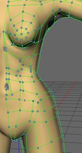
6 Now, move and scale the rows of vertices of the arm: Now, it's time to add the breasts. Add a Sphere, with subdivisions 8 and 8. Size it and move it. The sphere should be rotated so that the pole is in front. Then, rotate the sphere slighty outside: 6
.")
 in the mesh tools")
.")

7 Now, we will remove half of it: in the mesh tools toolbox ( ), use the cut tool ( ). In the tool, select the the define plane by vertices tool ( ). Then, select 3 vertices of the sphere that define the middle, the press 'Ok'. If the removed part is not the right one, use the symmetry tool ( ) in the mesh tools toolbox. When cutting a mesh, the cut plane is filled by faces. We need to remove them. Open the face toolbox ( ). Select the face created in the plane, and press 'Del' key, or use the delete tool ( ). We will now give it its form. For this, we will use the lattice modifier. In the mesh tools toolbox, opens the modifiers tool ( ). These opens the modifier selection window: 7

. First cut the mesh in the middle.")

8 Then, select the first one: the lattice modifier. Another way to open the lattice modifier is with the 'Effects >modifiers >lattice...' menu. Modifiers can be applied on mesh, faces, edges, or vertices. Select a 1x1x1 lattice. This create a lattice around the selected mesh. Now, you can move the lattice's points to deform the mesh. It is now time to join the elements together. So first, select all the pieces, and use the merge tool ( ). Give a name to the merged mesh. We will make the mesh symmetrical (so that we will work on one half, the other half will follow). First cut the mesh in the middle. If It is not the right part deleted, use undo ( )in the toolbar, use the symmetry tool, and cut the mesh again. Now, open the mirror tool ( ) in the mesh tools toolbox. This tools define a mirror plane with 3 vertices of the mesh. Select 3 vertices (in green) and the vertices in the mirror plane will be drawn in red: Then, press Ok, and answer Yes to create a symmetrical mesh. On a symmetrical mesh, the user can work on the green half, the blue will follow. 8


, the first")

9 We will join the leg and the body. First, select the top row of vertices of the leg, and place it so that it follow the model sheet. Select the outside faces of the leg, and use the hide tool ( ). Now, Select the 4 faces at the bottom of the body, and delete them. When 2 vertices are merged (welded), the first selected is moved to the second selected. So, as the vertices of the leg are in place, select the vertices of the body first. Then, use the weld vertices tool ( ). Continue around the lef/body: 9

.")


.")

. When this tool is activated,")


10 We will add a face to finish to link the leg and the body. Open the add face tool in the face toolbox ( ). Select the point of the face in clockwise order. Then press Ok. If the face is not visible, you need to flip it with. Now, open the edge toolbox ( ). Select the bottom edge of the body, and split it in two with the split edge tool ( ). Finaly, add an edge between the newly created vertex and the top of the leg with the add edge tool ( ). When this tool is activated, the user can draw edge between vertices of the same face. When the first vertex is selected, the possible targets are drawn in green. A bit of tweeking of the vertices, and it's done. 10


11 Now, we will add the faces one by one to connect the breast to the body. Add a face. Add a vertex on the top edge. Add another face... Now, tweek a little the vertices, and weld the top ones and add an edge: 11


12 Now, we will join the arm to the body. Rotate the arm. Select the faces of the arm. Delete the body face. Move, rotate and scale the two last row of vertices of the arm. 12


13 Split the edges of the body in 2. Weld the vertices of the body and the arm. Add a face at the top of the body. Split the edge in 7 parts to prepare the neck. Move the newly created vertices to form the base of the neck. Add Edges bewteen the nech and the shoulder. Select the edges, and use the split and connect tool ( ). Here the result. 13
.")

14 Remove an edge (yellow) and add one (red). Add a face for the neck. And extrude it 3 times ( in the face toolbox). The extrusions have created faces inside the neck. Select them and remove. Add a face for the neck. And extrude it 3 times ( in the face toolbox). Now, edit the vertices of the neck: 14


15 Back in mesh toolbox, press the 'Edit..' button in the material parameter. Create a new material, copy the default smooth one. Give it a name, like 'skin'. Then, select a new diffuse color, and press Ok. 15


16 Now, we will add the feet: Select the bottom face of the leg and extrude it. Select the 3 front faces of the leg and extrude them.. Now, select the vertices of the foot, and move them. Select the vertical edges of the foot, and cut and connect them. Move the created vertices, use the numerical values to make everything flat. Split the two edges at the top of the foor, connect them and the border. Tweek the vertices position. 16


17 Now, we will details... Let's start with the arm. Select the edges of the elbow and cut and connect them. Then, add the joining edges, and tweek the vertices positions. Do the same for the biceps: select the edges, cut and connect, add the 2 back edges and tweek the vertices positions. 17


18 Before going to the shoulder, we will make the armpit recess. Now, the shoulder. The clavicule The throat 18


19 The breast and the stomach. The vertices are move to mark the end of the torax. A line of edges is added sculpt the hip. The stomach is detailed, the hip too. 19


20 The nostril. more details. The nostril. 20
21 21
Character Modeling IAT 343 Lab 6. Lanz Singbeil
 Character Modeling IAT 343 Lab 6 Modeling Using Reference Sketches Start by creating a character sketch in a T-Pose (arms outstretched) Separate the sketch into 2 images with the same pixel height. Make
Autodesk Fusion 360: Model. Overview. Modeling techniques in Fusion 360
 Overview Modeling techniques in Fusion 360 Modeling in Fusion 360 is quite a different experience from how you would model in conventional history-based CAD software. Some users have expressed that it
CGS 3220 Lecture 13 Polygonal Character Modeling
 CGS 3220 Lecture 13 Polygonal Character Modeling Introduction to Computer Aided Modeling Instructor: Brent Rossen Overview Box modeling Polygon proxy Mirroring Polygonal components Topology editing Procedural
Create a Rubber Duck. This tutorial shows you how to. Create simple surfaces. Rebuild a surface. Edit surface control points. Draw and project curves
 Page 1 of 24 Create a Rubber Duck This exercise focuses on the free form, squishy aspect. Unlike the flashlight model, the exact size and placement of the objects is not critical. The overall form is the
This is the opening view of blender.
 This is the opening view of blender. Note that interacting with Blender is a little different from other programs that you may be used to. For example, left clicking won t select objects on the scene,
5 Subdivision Surfaces
 5 Subdivision Surfaces In Maya, subdivision surfaces possess characteristics of both polygon and NURBS surface types. This hybrid surface type offers some features not offered by the other surface types.
3D Design with 123D Design
 3D Design with 123D Design Introduction: 3D Design involves thinking and creating in 3 dimensions. x, y and z axis Working with 123D Design 123D Design is a 3D design software package from Autodesk. A
Editing Polygons. Adding material/volume: Extrude. Learning objectives
 Learning objectives Be able to: use the Extrude tool to add volume to a polygon know what edge loops are and how to insert edge loops in a polygon cut edges in a polygon know multiple methods of sewing
Modeling a Low-Poly Character
 NOTE Once you make a manual change to the original orientation of the normal, the normal changes to a green color, signifying that it's now an Explicit normal. 6 Experiment by selecting some of the other
Tutorial 2: Particles convected with the flow along a curved pipe.
 Tutorial 2: Particles convected with the flow along a curved pipe. Part 1: Creating an elbow In part 1 of this tutorial, you will create a model of a 90 elbow featuring a long horizontal inlet and a short
Rigging Half-Life 2 Bones
 Rigging Half-Life 2 Bones You have the bone in position with your model but of course the bone is not properly fits with your model size. In order to fix it: Resize or Move your model until its fits the
Box Modeling a Character Model Maya 2013
 2007-2013 Michael O'Rourke Box Modeling a Character Model Maya 2013 Concept When modeling a polygon character model, it can be faster to create a symmetrical model at first by working on only one half
Chair. Top Rail. on the Standard Views toolbar. (Ctrl-7) on the Weldments toolbar. at bottom left corner of display to deter- mine sketch plane.
 on the Weldments toolbar. at bottom left corner of display to deter- mine sketch plane.") Chapter 7 A. 3D Sketch. Step 1. If necessary, open your CHAIR file. Chair Top Rail Step 2. Click Isometric on the Standard Views toolbar. (Ctrl-7) Step 3. Zoom in around top of back leg, Fig. 1. To zoom,
Chapter 7 A. 3D Sketch. Step 1. If necessary, open your CHAIR file. Chair Top Rail Step 2. Click Isometric on the Standard Views toolbar. (Ctrl-7) Step 3. Zoom in around top of back leg, Fig. 1. To zoom,
Exercise Guide. Published: August MecSoft Corpotation
 VisualCAD Exercise Guide Published: August 2018 MecSoft Corpotation Copyright 1998-2018 VisualCAD 2018 Exercise Guide by Mecsoft Corporation User Notes: Contents 2 Table of Contents About this Guide 4
3D Modeling Course Outline
 3D Modeling Course Outline Points Possible Course Hours Course Overview 4 Lab 1: Start the Course Identify computer requirements. Learn how to move through the course. Switch between windows. Lab 2: Set
Transforming Objects and Components
 4 Transforming Objects and Components Arrow selection Lasso selection Paint selection Move Rotate Scale Universal Manipulator Soft Modification Show Manipulator Last tool used Figure 4.1 Maya s manipulation
Autodesk Inventor Design Exercise 2: F1 Team Challenge Car Developed by Tim Varner Synergis Technologies
 Autodesk Inventor Design Exercise 2: F1 Team Challenge Car Developed by Tim Varner Synergis Technologies Tim Varner - 2004 The Inventor User Interface Command Panel Lists the commands that are currently
Modeling Technology Group
 Modeling Technology Group Hiroshi Hayashi David Ogirala Matt Nedrich Jeff Ridenbaugh Spencer Smith Saba Bokhari John Gray Charles Hellstrom Bryan Linthicum Polygon Models (part-1) What are polygons? -
Chapter 15: Penguin - Point Editing and Blending
 This tutorial demonstrates point-editing techniques including moving and scaling control points and adding knots to surfaces to increase control. In addition, you will use blends to create smooth transitions
BlockMan Directions V2 Computer Graphics and Animation. Description:
 BlockMan Directions V2 Computer Graphics and Animation Description: These directions work through modeling, creating a skeleton, skinning, UV map, and animation of a block figure with Maya 2015. This process
AUTODESK FUSION 360 Designing a RC Car Body
 AUTODESK FUSION 360 Designing a RC Car Body Abstract This project explores how to use the sculpting tools available in Autodesk Fusion 360 Ultimate to design the body of a RC car. John Helfen john.helfen@autodesk.com
Character Modeling COPYRIGHTED MATERIAL
 38 Character Modeling p a r t _ 1 COPYRIGHTED MATERIAL 39 Character Modeling Character Modeling 40 1Subdivision & Polygon Modeling Many of Maya's features have seen great improvements in recent updates
Lesson 1: Creating T- Spline Forms. In Samples section of your Data Panel, browse to: Fusion 101 Training > 03 Sculpt > 03_Sculpting_Introduction.
 3.1: Sculpting Sculpting in Fusion 360 allows for the intuitive freeform creation of organic solid bodies and surfaces by leveraging the T- Splines technology. In the Sculpt Workspace, you can rapidly
Freeform / Freeform PLUS
 Freeform / Freeform PLUS WORKING WITH FREEFORM Work from Coarse Clay to Fine When creating new models from scratch, it is best to first create a rough shape using a coarse clay setting such as Rough Shape
ARCHITECTURE & GAMES. A is for Architect Simple Mass Modeling FORM & SPACE. Industry Careers Framework. Applied. Getting Started.
 A is for Architect Simple Mass Modeling One of the first introductions to form and space usually comes at a very early age. As an infant, you might have played with building blocks to help hone your motor
A Guide to Autodesk Maya 2015
 A Guide to Autodesk Maya 2015 Written by Mitchell Youngerman Table of Contents Layout of Toolbars...pg 1 Creating Objects...pg 2 Selecting & Deselecting Objects...pg 3 Changing Perspective... pg 4 Transforming
S206E Lecture 3, 5/15/2017, Rhino 2D drawing an overview
 Copyright 2017, Chiu-Shui Chan. All Rights Reserved. S206E057 Spring 2017 Rhino 2D drawing is very much the same as it is developed in AutoCAD. There are a lot of similarities in interface and in executing
Beginners Guide Maya. To be used next to Learning Maya 5 Foundation. 15 juni 2005 Clara Coepijn Raoul Franker
 Beginners Guide Maya To be used next to Learning Maya 5 Foundation 15 juni 2005 Clara Coepijn 0928283 Raoul Franker 1202596 Index Index 1 Introduction 2 The Interface 3 Main Shortcuts 4 Building a Character
Chapter 3- Creating & Editing Objects
 ` Chapter 3- Creating & Editing Objects Edit Mode- Mesh Editing Object Mode After you have created a mesh, you can go into Edit mode (Tab key or Mode option in window) and change its shape. In edit mode,
TerraScan Tool Guide
 TerraScan Main Toolbox General Toolbar Draw Toolbar Groups Toolbar Vectorize Towers Toolbar Road Toolbar Buildings Toolbar Building Edges Toolbar View Laser Toolbar Model Toolbar Vectorize Wires Toolbar
1st Point. 2nd Point. hold shift & drag along Y. Splines
 Splines STEP 1: open 3DS Max _ from the Command Panel under the Create tab click on Shapes (note: shapes are really Splines) _ under Object Type click on Ellipse STEP 2: Expand the Keyboard Entry tab type
solidthinking Inspired Tutorials 2009 solidthinking, Inc. for Mac
 solidthinking Inspired Tutorials 2009 solidthinking, Inc. for Mac Table of Contents Quick Start Tutorials 3 Tutorial 11: Simple... Bridge 4 Tutorial 22: Desk... 12 Tutorial 33: Bookcase... 35 2 1 Quick
NURBS modeling for Windows. Training Manual Level 1
 NURBS modeling for Windows Training Manual Level 1 Rhino Level 1 Training 2nd Ed.doc Robert McNeel & Associates 1997-2000 All Rights Reserved. Printed in U.S.A. Copyright by Robert McNeel & Associates.
Geometric Entities for Pilot3D. Copyright 2001 by New Wave Systems, Inc. All Rights Reserved
 Geometric Entities for Pilot3D Copyright 2001 by New Wave Systems, Inc. All Rights Reserved Introduction on Geometric Entities for Pilot3D The best way to develop a good understanding of any Computer-Aided
Animator Friendly Rigging Part 2b
 Animator Friendly Rigging Part 2b Creating animation rigs which solve problems, are fun to use, and don t cause nervous breakdowns. - 1- CONTENTS Review The Requirements... 5 Torso Animation Rig Requirements...
User Interface Software Projects
 User Interface Software Projects Assoc. Professor Donald J. Patterson INF 134 Winter 2013 The author of this work license copyright to it according to the Creative Commons Attribution-Noncommercial-Share
It is a good idea to practice View Control tools for 5 minutes at the start of every 3D session, before doing any other work.
 3D View Control Module Overview All the 2D view controls, such as Fit View, Zoom In and Out, Window Area, and Pan, can be used in 3D. As in 2D, elements to the left, right, above, or below can be excluded
Solidworks 2006 Surface-modeling
 Solidworks 2006 Surface-modeling (Tutorial 2-Mouse) Surface-modeling Solid-modeling A- 1 Assembly Design Design with a Master Model Surface-modeling Tutorial 2A Import 2D outline drawing into Solidworks2006
Notes on Blender: By Matthew Evett
 Notes on Blender: By Matthew Evett A synopsis of the Wiki: http://en.wikibooks.org/wiki/blender_3d:_noob_to_pro The Blender GUI is implemented via opengl. Thus the GUI is not Windowsstandard. Can resize
3 Polygonal Modeling. Getting Started with Maya 103
 3 Polygonal Modeling In Maya, modeling refers to the process of creating virtual 3D surfaces for the characters and objects in the Maya scene. Surfaces play an important role in the overall Maya workflow
Let a line l and a point P not lying on it be given. By using properties of a transversal and parallel lines, a line which passes through the point P
 Let a line l and a point P not lying on it be given. By using properties of a transversal and parallel lines, a line which passes through the point P and parallel to l, can be drawn. A triangle can be
3ds Max Cottage Step 1. Always start out by setting up units: We re going with this setup as we will round everything off to one inch.
 3ds Max Cottage Step 1 Always start out by setting up units: We re going with this setup as we will round everything off to one inch. File/Import the CAD drawing Be sure Files of Type is set to all formats
XSI TO SINS: COMMANDS & SHORTCUTS
 XSI TO SINS: COMMANDS & SHORTCUTS I. Commonly Used Basic Modeling Commands and Shortcuts in XSI: Section A: The Main Control Panel Select Menu Group/Cluster Selection (See Fig. 1.1 for a quick visual overview)
Autodesk Fusion 360 Training: The Future of Making Things Attendee Guide
 Autodesk Fusion 360 Training: The Future of Making Things Attendee Guide Abstract After completing this workshop, you will have a basic understanding of editing 3D models using Autodesk Fusion 360 TM to
To familiarize of 3ds Max user interface and adapt a workflow based on preferences of navigating Autodesk 3D Max.
 Job No: 01 Duration: 8H Job Title: User interface overview Objective: To familiarize of 3ds Max user interface and adapt a workflow based on preferences of navigating Autodesk 3D Max. Students should be
Sculpting 3D Models. Glossary
 A Array An array clones copies of an object in a pattern, such as in rows and columns, or in a circle. Each object in an array can be transformed individually. Array Flyout Array flyout is available in
Blender Lesson Ceramic Bowl
 Blender Lesson Ceramic Bowl This lesson is going to show you how to create a ceramic looking bowl using the free program Blender. You will learn how to change the view, add, delete, scale and edit objects
Module 1B: Parallel-Line Flat Pattern Development of Sheet- Metal Folded Model Wrapping the 3D Space of A Truncated Right Prism
 Inventor (5) Module 1B: 1B- 1 Module 1B: Parallel-Line Flat Pattern Development of Sheet- Metal Folded Model Wrapping the 3D Space of A Truncated Right Prism In this Module, we will learn how to create
Course: 3D Design Title: Mesh Modeling Hand Dropbox File: Hand.zip Blender: Version 2.41 Level: Beginning Author; Neal Hirsig
 Course: 3D Design Title: Mesh Modeling Hand Dropbox File: Hand.zip Blender: Version 2.41 Level: Beginning Author; Neal Hirsig (nhirsig@tufts.edu) Mesh Modeling Hand Open a new Blender file. We will be
XPEL DAP SUPPORT. DAP Tool List & Overview DESCRIPTION ICON/TOOL (SHORTCUT)
") Pointer (S) Left-click on individual entities to add them to the current selection (selected entities will turn red). If the entity selected is a member of a group, the entire group will be added to the
Pointer (S) Left-click on individual entities to add them to the current selection (selected entities will turn red). If the entity selected is a member of a group, the entire group will be added to the
TUTORIAL 2. OBJECTIVE: Use SolidWorks/COSMOS to model and analyze a cattle gate bracket that is subjected to a force of 100,000 lbs.
 TUTORIAL 2 OBJECTIVE: Use SolidWorks/COSMOS to model and analyze a cattle gate bracket that is subjected to a force of 100,000 lbs. GETTING STARTED: 1. Open the SolidWorks program. 2. Open a new part file.
SolidWorks 2½D Parts
 SolidWorks 2½D Parts IDeATe Laser Micro Part 1b Dave Touretzky and Susan Finger 1. Create a new part In this lab, you ll create a CAD model of the 2 ½ D key fob below to make on the laser cutter. Select
COMPUTER AIDED ARCHITECTURAL GRAPHICS FFD 201/Fall 2013 HAND OUT 1 : INTRODUCTION TO 3D
 COMPUTER AIDED ARCHITECTURAL GRAPHICS FFD 201/Fall 2013 INSTRUCTORS E-MAIL ADDRESS OFFICE HOURS Özgür Genca ozgurgenca@gmail.com part time Tuba Doğu tubadogu@gmail.com part time Şebnem Yanç Demirkan sebnem.demirkan@gmail.com
How to Use a Push Modifier: Creating a Blanket and Adjusting Clothing Fit
 How to Use a Push Modifier: Creating a Blanket and Adjusting Clothing Fit Copyright 2017 by Rich Schafermeyer (RGcincy on Daz Forums) This is a tutorial on using a push modifier so that a primitive plane
Tutorial Model the perfect 3D face
 Model the perfect D face Want to get your head around D modelling? We use Maya to show you how to build an animatable face feature by feature T here are many ways in which to model a head in D. In this
Project 3. Top Down Design In Context. Below are the desired outcomes and usage competencies based upon the completion of this Project.
 Assembly Modeling with SolidWorks Project 3 Below are the desired outcomes and usage competencies based upon the completion of this Project. Project Desired Outcomes: 2AXIS-TRANSFER Assembly. PLATE-B Part.
QuickTutor. An Introductory SilverScreen Modeling Tutorial. Solid Modeler
 QuickTutor An Introductory SilverScreen Modeling Tutorial Solid Modeler TM Copyright Copyright 2005 by Schroff Development Corporation, Shawnee-Mission, Kansas, United States of America. All rights reserved.
PRACTICAL GEOMETRY SYMMETRY AND VISUALISING SOLID SHAPES
 UNIT 12 PRACTICAL GEOMETRY SYMMETRY AND VISUALISING SOLID SHAPES (A) Main Concepts and Results Let a line l and a point P not lying on it be given. By using properties of a transversal and parallel lines,
Introduction to SolidWorks for Technology. No1: Childs Toy
 Introduction to SolidWorks for Technology No1: Childs Toy Table of Contents Table of Contents... 1 Introduction... 2 Part Modelling: Cab... 3 Part Modelling: Base... 6 Part Modelling: Wheel... 12 Assembly:
Images from 3D Creative Magazine. 3D Modelling Systems
 Images from 3D Creative Magazine 3D Modelling Systems Contents Reference & Accuracy 3D Primitives Transforms Move (Translate) Rotate Scale Mirror Align 3D Booleans Deforms Bend Taper Skew Twist Squash
Learning. Modeling, Assembly and Analysis SOLIDWORKS Randy H. Shih SDC. Better Textbooks. Lower Prices.
 Learning SOLIDWORKS 2016 Modeling, Assembly and Analysis Randy H. Shih SDC PUBLICATIONS Better Textbooks. Lower Prices. www.sdcpublications.com Powered by TCPDF (www.tcpdf.org) Visit the following websites
SolidWorks Intro Part 1b
 SolidWorks Intro Part 1b Dave Touretzky and Susan Finger 1. Create a new part We ll create a CAD model of the 2 ½ D key fob below to make on the laser cutter. Select File New Templates IPSpart If the SolidWorks
Pagoda/Hypar 3. Manual
 Pagoda/Hypar 3 Manual Armstrong-White Automation (NZ) Ltd Armstrong-White Automation (NZ) Ltd 22 Kereru Grove, Greenhithe, North Shore City 0632 (Auckland), New Zealand. ph +64 9 413-7642 fax +64 9 413-7643
Creating an Excel resource
 Excel Mobile Excel Mobile is a Microsoft application similar to Excel, but designed to run on handhelds. This mobile version of Excel is a spreadsheet application that allows you to manipulate numbers,
Rhinoceros NURBS modeling for Windows. Version 1.0 Training Manual Level 1
 Rhinoceros NURBS modeling for Windows Version 1.0 Training Manual Level 1 rhinolevel 1.doc Robert McNeel & Associates 1997. All Rights Reserved. Printed in U.S.A. Copyright by Robert McNeel & Associates.
Spring 2011 Workshop ESSENTIALS OF 3D MODELING IN RHINOCEROS February 10 th 2011 S.R. Crown Hall Lower Core Computer Lab
 [1] Open Rhinoceros. PART 1 INTRODUCTION [4] Click and hold on the Boundary Lines in where they form a crossing and Drag from TOP RIGHT to BOTTOM LEFT to enable only the PERSPECTIVE VIEW. [2] When the
Dave s Phenomenal Maya Cheat Sheet Polygon Modeling Menu Set By David Schneider
 Dave s Phenomenal Maya Cheat Sheet Polygon Modeling Menu Set By David Schneider POLYGONS NURBS to Polygons This allows the user to change the objects created with NURBS into polygons so that polygon tools
Boat Hull Solid. (Alt-2). in ribbon bar to fix and close ribbon Fig. 3 Mastercam X7 BOAT HULL SOLID Page 29-1
. in ribbon bar to fix and close ribbon Fig. 3 Mastercam X7 BOAT HULL SOLID Page 29-1") Mastercam X7 Chapter 29 A. Open Boat Block File. Step 1. Open your BOAT BLOCK file. Boat Hull Solid B. Save As BOAT HULL SOLID Step 1. Click File Menu > Save As. Step 2. Key-in BOAT HULL SOLID for the
Mastercam X7 Chapter 29 A. Open Boat Block File. Step 1. Open your BOAT BLOCK file. Boat Hull Solid B. Save As BOAT HULL SOLID Step 1. Click File Menu > Save As. Step 2. Key-in BOAT HULL SOLID for the
Chapter 11 Solar Car Drawing
 Chapter 11 Solar Car Drawing A. Insert Top and Side Views. Step 1. Click File Menu > New, click Drawing and OK. Step 2. Click Browse Step 3. Select your solar car assembly file and click Open. Step 4.
Introduction to SolidWorks Basics Materials Tech. Wood
 Introduction to SolidWorks Basics Materials Tech. Wood Table of Contents Table of Contents... 1 Book End... 2 Introduction... 2 Learning Intentions... 2 Modelling the Base... 3 Modelling the Front... 10
Basics of Design p. 2 Approaching Design as an Artist p. 4 Knowing Your Character p. 4 Making Decisions p. 4 Categories of Design p.
 Basics of Design p. 2 Approaching Design as an Artist p. 4 Knowing Your Character p. 4 Making Decisions p. 4 Categories of Design p. 6 Realistic Designs p. 6 Stylized Designs p. 7 Designing a Character
Exercise 1a: Interacting With HyperMesh
 Exercise 1a: Interacting With HyperMesh This exercise will cover many of the basic concepts that are central to many of the features in HyperMesh. By the end of this exercise you should be familiar with
Maya Lesson 6 Screwdriver Notes & Assessment
 Maya Lesson 6 Screwdriver Notes & Assessment Save a new file as: Lesson 6 Screwdriver YourNameInitial Save in your Computer Animation folder. Screwdriver Handle Base Using CVs Create a polygon cylinder
Chapter 2 Parametric Modeling Fundamentals
 2-1 Chapter 2 Parametric Modeling Fundamentals Create Simple Extruded Solid Models Understand the Basic Parametric Modeling Procedure Create 2-D Sketches Understand the Shape before Size Approach Use the
Systems Space Reservation
 Systems Space Reservation Preface Using This Guide What's New? Getting Started Enter the Workbench Create an Equipment Reservation Set Correct Working Units and Grid Changing the Current Axis Saving Documents
Lesson 1 Parametric Modeling Fundamentals
 1-1 Lesson 1 Parametric Modeling Fundamentals Create Simple Parametric Models. Understand the Basic Parametric Modeling Process. Create and Profile Rough Sketches. Understand the "Shape before size" approach.
Solid Modeling: Part 1
 Solid Modeling: Part 1 Basics of Revolving, Extruding, and Boolean Operations Revolving Exercise: Stepped Shaft Start AutoCAD and use the solid.dwt template file to create a new drawing. Create the top
Skateboard. Hanger. in the Feature Manager and click Sketch on the Context toolbar, Fig. 1. Fig. 2
 Chapter 3 Skateboard Hanger A. Sketch1 Lines. Step 1. Click File Menu > New, click Part Metric and OK. Step 2. Click Right Plane in the Feature Manager and click Sketch on the Context toolbar, Fig. 1.
Body. Chapter 2. CO2 Rail Car E. A. Save as "BODY RAIL E". Step 1. Open your BLANK file.
 Chapter 2 A. Save as "BODY RAIL E". Step 1. Open your BLANK file. Step 2. Click File Menu > Save As. Step 3. Key-in BODY RAIL E for the filename and press ENTER. CO2 Rail Car E Body B. Appearance. Step
Oasys GSA. Getting Started
 Getting Started 13 Fitzroy Street London W1T 4BQ Telephone: +44 (0) 20 7755 3302 Facsimile: +44 (0) 20 7755 3720 Central Square Forth Street Newcastle Upon Tyne NE1 3PL Telephone: +44 (0) 191 238 7559
Presets are the heart of Genoma. They can be added to so you can build up a library of reusable rig parts or even complete rigs to suit your
 Genoma 1 Genoma 1 Presets Presets are the heart of Genoma. They can be added to so you can build up a library of reusable rig parts or even complete rigs to suit your needs. Opening the Genoma Presets
Notes 2 My Notes and Thoughts Blender Rigify. Categories : Uncategorised. Date : 19th November / 43
 Blender Rigify Categories : Uncategorised Date : 19th November 2017 1 / 43 Rigify is an incredibly useful tool for getting characters rigged in a jiffy. Instead of spending days setting up a rig by hand,
Threaded Hex Bolt Tutorial
 1-(800) 877-2745 www.ashlar-vellum.com Tutorial Using Cobalt, Xenon, Argon Copyright 2009-2014 Vellum Investment Partners, LLC, DBA Ashlar-Vellum. All rights reserved. Ashlar-Vellum Cobalt, Xenon & Argon
AgWare ClickFORMS 7.0 Introductory Tutorial
 AgWare ClickFORMS 7.0 Introductory Tutorial MAIN WINDOW If you have used Office 2007, our new layout will look familiar. Here is a screenshot of the new and improved AgWare ClickFORMS window: The Forms
Basic Blender Commands This is just a partial list of Blender commands. Please visit the Blender.org website for more details.
 Basic Key Commands Basic Blender Commands This is just a partial list of Blender commands. Please visit the Blender.org website for more details. TAB key- Toggles between edit mode (vertex editing) and
Brief 3ds max Shaping Tutorial
 Brief 3ds max Shaping Tutorial Part1: Power Key Axe Shaft Written by Maestro 1. Creation: Go to top view, create a 6 sided cylinder, 0.1 radius this is the perfect shaft thickness to fit in the hand, so
QUICK-START TUTORIALS
 PUERMC02_0132276593.QXD 08/09/2006 06:05 PM Page 83 QUICK-START TUTORIALS Chapter Objectives Create two real 3D modeling projects, starting them from scratch. Know the difference between representing 3D
Table of contents 2 / 117
 1 / 117 Table of contents Welcome... 4 System requirements... 5 Getting help... 6 Commands... 7 Primitives... 10 Plane... 11 Box... 13 Torus... 15 Cylinder... 18 Sphere... 20 Ellipsoid... 22 Cone... 24
Using the CMA Warp Editor
 Using the CMA Warp Editor Overview The Warp Editor feature lets you adjust Axon HD, Axon HD Pro, DLHD or MMS100 output to match complex projection surfaces. These forms allow the projection to match irregular
Reset Cursor Tool Clicking on the Reset Cursor tool will clear all map and tool selections and allow tooltips to be displayed.
 SMS Featured Icons: Mapping Toolbar This document includes a brief description of some of the most commonly used tools in the SMS Desktop Software map window toolbar as well as shows you the toolbar shortcuts
3DS Max Tutorial Surface, Shell, Editable Mesh and Mesh Smooth.
 3DS Max Tutorial Surface, Shell, Editable Mesh and Mesh Smooth. This is a tutorial that shows how to use the 3D Studio Max modifiers Surface and Shell and how to work with meshes. To start with you really
Extrusion Revolve. ENGR 1182 SolidWorks 02
 Extrusion Revolve ENGR 1182 SolidWorks 02 Today s Objectives Creating 3D Shapes from 2D sketches using: Extrusion Revolve SW02 In-Class Activity Extrude a Camera Revolve a Wheel SW02 Out-of-Class Homework
Photoshop Tutorial: Removing the Background from an Image
 Photoshop Tutorial: Removing the Background from an Image I. Downloading & Opening the file. II. Magic Wand (tomato) Type the following into your browser window to download the source file: da7913.kocfiles.net/veggies.psd
Airplane Assembly. SolidWorks 10 ASSEMBLY AIRPLANE Page 9-1
 Chapter 9 A. Insert Parts. Airplane Assembly Step 1. Click File Menu > New, click Assembly and OK. Step 2. Click Keep Visible in the Property Manager, Fig. 1. Step 3. Click Browse in the Property Manager,
Fusion 360: Bridging Concept Design and Mechanical Design
 Fusion 360: Bridging Concept Design and Mechanical Design Tanner Reid Autodesk Sachlene Singh - Autodesk CD7049-L Learning Objectives At the end of this class, you will be able to: Conceptualize multiple
Additional Surface Tools
 Additional Surface Tools Several additional surface tools, techniques, and related functions are available. This supplement provides a brief introduction to those functions. Panel Part Features Replace
Designing a Chair. Lesson 6
 Lesson 6 Designing a Chair This lesson illustrates how to design a chair using the Curves Network modeling tool. The following modeling tools will be covered: Curves Network. Skin. Intersect. Trim. Mirror.
Select, Move, Rotate and Scale
 Select, Move, Rotate and Scale In this tutorial we will cover the basic tools necessary for navigating, moving, and manipulating objects in 3DS Max. It is less of a how to tutorial and more of a guide
Mastercam X9 for SOLIDWORKS
 Chapter 21 CO2 Shell Car Mastercam X9 for SOLIDWORKS A. Enable Mastercam for SOLIDWORKS. Step 1. If necessary, turn on Mastercam for SOLIDWORKS, click the flyout of Options on the Standard toolbar and
NURBS Sailboat on Ocean (Modeling/Animation)
") Course: 3D Design Title: NURBS Sailboat Blender: Version 2.6X Level: Beginning Author; Neal Hirsig (nhirsig@tufts.edu) (April 2013) NURBS Sailboat on Ocean (Modeling/Animation) The objective of this PDF
Course: 3D Design Title: NURBS Sailboat Blender: Version 2.6X Level: Beginning Author; Neal Hirsig (nhirsig@tufts.edu) (April 2013) NURBS Sailboat on Ocean (Modeling/Animation) The objective of this PDF