Table of contents 2 / 117
|
|
|
- Hollie McDonald
- 5 years ago
- Views:
Transcription

1 1 / 117
2 Table of contents Welcome... 4 System requirements... 5 Getting help... 6 Commands... 7 Primitives Plane Box Torus Cylinder Sphere Ellipsoid Cone Truncated Cone Pipe Creation Create by curve Create by two curves Create by surfaces Create by meshes Loft Sweep Sweep Revolve Ring Blueprint Retopology To Nurbs Edition Delete Add Face Divide Split sides Merge Extract Inset Collapse Extrude Shell Offset Bridge Fill Match Match to curve Project to Plane Flip Unify Normals Crease edges / 117
3 Uncrease edges Analyze distances Selection Select all Select none Invert Select Clayoo surfaces Select crease edges Select uncrease edges Select naked edges Paint selection Selection grow Selection shrink Select U Select V Sets Select ring edges Select loop edges Set plane Viewport tools Visualization mode Selection mode Smooth up/down Gumball modes and tools Options Keyboard Check Updates Licensing TDM Solutions SL / 117
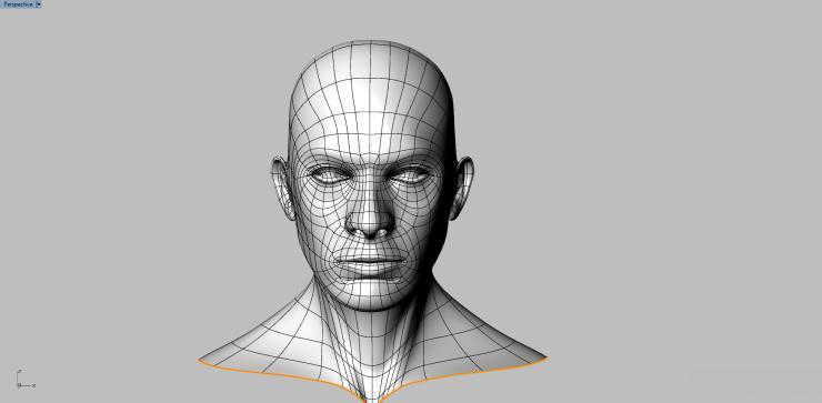
4 Welcome Clayoo is an advanced modeling application with the ability to effortlessly create any form efficiently and accurately, however complex. It's like modeling by hand! This is the concept of Clayoo. It doesn't matter whether you start from a sketch, curve, or a 3-D object, you can pull, push, and move until you get what you want. Ideal for designing architecture, jewelry, consumer products, toys, aerospace, marine, furniture. Anyone who needs to create complex free-form shapes can use Clayoo. When precision is a must Clayoo offers real-time tools to analyze distances, variance draft angle, thickness and more. Not only modeling, but manufacturing. Clayoo geometry is great for manufacturing prototypes and molds. When exporting to STL Clayoo automatically generates closed meshes. For reverse engineering with advanced re-topology tools Clayoo allows you to easily create surfaces over digitized objects and to convert the result as NURBS surfaces. Key Benefits Unlimited creation and modification Model from any geometry: surfaces, solids, meshes, or from a sketch. Edit using the most advanced tool as join, break, divide, separate, offset, raise, move, extrude, plunge, shell, and much more. The possibilities are endless. Reverse engineer scan data, and STL meshes to Clayoo surfaces or NURBS. Control and accuracy Works accurately, freely, or both. Define more control points in areas that require it. Advanced offset, shell, and bridge connection. High performance definition of detail areas Allows varying levels of detail across one object. For example, when modeling a face, you can use higher definition around the eyes and eyebrows. 100% compatibility with Rhino surfaces The Clayoo plug-in has been created by TDM Solutions in and for Rhinoceros. 4 / 117
5 System requirements Clayoo runs on ordinary Windows desktop and laptop computers, with: Minimal System Requirements Pentium, Celeron, or higher processor. 200 MB disk space. 512 MB RAM. 1 GB or more is recommended. OpenGL graphic card recommended. Clayoo runs only on Windows 2000, Windows XP Pro, Windows XP Home, Windows Vista, Windows 7 including an Intel Mac with BootCamp. Recommended System Requierements Intel Core i3 or higher processor. 200 MB disk space. 2Gb. 4 GB or more is recommended. OpenGL graphic card Windows 7 or higher. Clayoo does run on Windows 32-bit and 64-bit. Is highly recommended to use 64-bit. 5 / 117
6 Getting help Support is included even before buying. There are several ways to access the support Clayoo: Technical Forum On the website of Clayoo ( can find the forum. It's a great tool to ask your questions. It is best to get answers from Clayoo tech support and other users around the world. Write us to support@tdmsolutions.com. The response time is 3 hours to 48 hours. Phone Telephone support is available on (CET) from Monday to Thursday ( and ) and Friday (9-14). 6 / 117

7 Commands All the Clayoo commands are available in three different ways: Menu, toolbar and typing the command name. Menu As Rhinoceros, Clayoo creates a menu at the top of the screen. As you will see below, the menu is created using the same structure of the toolbars. Toolbar The toolbar is the fastest way to access commands Clayoo. When installing Clayoo appears the main toolbar. As we show below, there are icons that have a small triangle in the bottom right. If we click on these icons will show us another toolbar with more commands. The toolbars are native Rhinoceros Clayoo. For this reason, you can configure it at will. 7 / 117


8 Primitives Toolbar This toolbar contains the commands to create basic geometries as plane, box, torus, cylinder,... Create Toolbar This toolbar contains tools for creating Clayoo surfaces. There are several ways to create from curves, surfaces, meshes,... The following sections detail each one of the tools. Edition Toolbar This toolbar contains tools for editing Clayoo surfaces. Tools from delete, add, divide, shell, extrude,... The following sections detail each one of the tools. Selection Toolbar This toolbar contains tools for selecting Clayoo surfaces: Select All, None, Invert, Select edges, Selection U, Selection V,... 8 / 117

9 Commands All the commands of Clayoo start with Clay---. You can type the command in the CommandPrompt: 9 / 117
10 Primitives This toolbar contains the commands to create basic geometries as plane, box, torus, cylinder,... Primitive Icon Command Plane Box Torus Cylinder Sphere Ellipsoid Cone Truncated Cone Pipe ClayPlane ClayBox ClayTorus ClayCylinder ClaySphere ClayEllipsoid ClayCone ClayTruncatedCone ClayPipe 10 / 117


11 Plane Toolbar Menu Command Clayoo > Primitives > Plane Clayoo > Primitives > Plane ClayPlane This tool allows us to create flat surfaces. By default, creates the surface in the CPlane of the active view. When you run the command, it will display a dialog where you can change the following parameters: The values X and Y are the size. Also you can resize dynamically with the red arrows. You can double-click on the red arrows to define a value. Div values specify the divisions in X and Y. This allows us to define more or less number of faces. Pressing CTRL will change all divisions at a time. The following shows the same surface with different divisions: 11 / 117


12 Smooth option allows to preview the Plane in smooth mode. Displayed an orange circle in the center of the surface. This allows us to move the surface in the plane. Similarly, if we double click on the circle, you can pick a point. Once defined the surface as needed, click the OK button, or X to cancel the command. 12 / 117


13 Box Toolbar Menu Command Clayoo > Primitives > Box Clayoo > Primitives > Box ClayBox This tool allows us to create a Box. By default, creates the surface in the CPlane of the active view. When you run the command, it will display a dialog where you can change the following parameters: The values X, Y and Z are the size. Also you can resize dynamically with the red arrows. You can double-click on the red arrows to define a value. Div values specify the divisions in X, Y and Z. This allows us to define more or less number of faces. Pressing CTRL will change all divisions at a time. The following shows the same surface with different divisions: 13 / 117


14 Smooth option allows to preview the Box in smooth mode. Displayed an orange circle in the center of the surface. This allows us to move the surface in the plane. Similarly, if we double click on the circle, you can pick a point. Once defined the surface as needed, click the OK button, or X to cancel the command. 14 / 117


15 Torus Toolbar Menu Command Clayoo > Primitives > Torus Clayoo > Primitives > Torus ClayTorus This tool allows us to create a Torus. By default, creates the surface in the CPlane of the active view. When you run the command, it will display a dialog where you can change the following parameters: The values Radius 1 and Radius 2 are the size of the torus. Also you can resize dynamically with the red arrows. You can double-click on the red arrows to define a value. 15 / 117


16 Div values specify the divisions. This allows us to define more or less number of faces. Pressing CTRL will change all divisions at a time. The following shows the same surface with different divisions: Smooth option allows to preview the Torus in smooth mode. Displayed an orange circle in the center of the surface. This allows us to move the 16 / 117

17 surface in the plane. Similarly, if we double click on the circle, you can pick a point. Once defined the surface as needed, click the OK button, or X to cancel the command. 17 / 117


18 Cylinder Toolbar Menu Command Clayoo > Primitives > Cylinder Clayoo > Primitives > Cylinder ClayCylinder This tool allows us to create a Cylinder. By default, creates the surface in the CPlane of the active view. When you run the command, it will display a dialog where you can change the following parameters: You can define the radius and the height. Also you can resize dynamically with the red arrows. You can double-click on the red arrows to define a value. 18 / 117


19 Div values specify the divisions. This allows us to define more or less number of faces. Pressing CTRL will change all divisions at a time. The following shows the same surface with different divisions: Cap and Crease allows to cap the cylinder. (Left: Cap and Crease Right: Cap) Smooth option allows to preview the cylinder in smooth mode. Displayed an orange circle in the center of the surface. This allows us to move the surface in the plane. Similarly, if we double click on the circle, you can pick a point. Once defined the surface as needed, click the OK button, or X to cancel the command. 19 / 117


20 Sphere Toolbar Menu Command Clayoo > Primitives > Sphere Clayoo > Primitives > Sphere ClaySphere This tool allows us to create a Sphere. By default, creates the surface in the CPlane of the active view. When you run the command, it will display a dialog where you can change the following parameters: You can define the radius. Also you can resize dynamically with the red arrow. You can double-click on the red arrows to define a value. Div values specify the divisions. This allows us to define more or less number of faces. Pressing CTRL will change all divisions at a time. 20 / 117
 Smooth option allows to preview the sphere in smooth")

21 Quad Sphere allows to define the sphere in quad faces. (Left: Quad Sphere Unchecked Right: Quad Sphere Checked) Smooth option allows to preview the sphere in smooth mode. Displayed an orange circle in the center of the surface. This allows us to move the surface in the plane. Similarly, if we double click on the circle, you can pick a point. Once defined the surface as needed, click the OK button, or X to cancel the command. 21 / 117


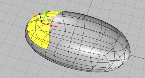
22 Ellipsoid Toolbar Menu Command Clayoo > Primitives > Ellipsoid Clayoo > Primitives > Ellipsoid ClayEllipsoid This tool allows us to create a Ellipsoid. By default, creates the surface in the CPlane of the active view. When you run the command, it will display a dialog where you can change the following parameters: The values Radius X, Radius Y and Radius Z are the sizes. Also you can resize dynamically with the red arrows. You can double-click on the red arrows to define a value. 22 / 117


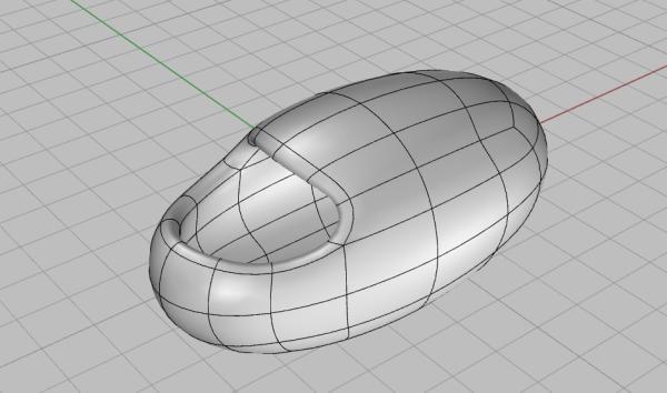
23 Div values specify the divisions in X, Y and Z. This allows us to define more or less number of faces. Pressing CTRL will change all divisions at a time. Quad Ellipsoid allows to define the ellipsoid in quad faces. (Left: Quad Ellipsoid Unchecked Right: Quad Ellipsoid Checked) Smooth option allows to preview the Ellipsoid in smooth mode. Displayed an orange circle in the center of the surface. This allows us to move the surface in the plane. Similarly, if we double click on the circle, you can pick a point. Once defined the surface as needed, click the OK button, or X to cancel the command. 23 / 117


24 Cone Toolbar Menu Command Clayoo > Primitives > Cone Clayoo > Primitives > Cone ClayCone This tool allows us to create a Cone. By default, creates the surface in the CPlane of the active view. When you run the command, it will display a dialog where you can change the following parameters: Radius and Height define the size of the cone. Also you can resize dynamically with the red arrows. You can double-click on the red arrows to define a value. Div values specify the divisions. This allows us to define more or less number of faces. Pressing CTRL will change all divisions at a time. 24 / 117
 Smooth option allows to preview the Cone in smooth mode.")

25 Cap and Crease allows to cap the cylinder. (Left: Cap and Crease Right: Cap) Smooth option allows to preview the Cone in smooth mode. Displayed an orange circle in the center of the surface. This allows us to move the surface in the plane. Similarly, if we double click on the circle, you can pick a point. Once defined the surface as needed, click the OK button, or X to cancel the command. 25 / 117


26 Trucanted Cone Toolbar Menu Command Clayoo > Primitives > Truncated Cone Clayoo > Primitives > Truncated Cone ClayTruncatedCone This tool allows us to create a Truncated Cone. By default, creates the surface in the CPlane of the active view. When you run the command, it will display a dialog where you can change the following parameters: Radius and Height define the size of the cone. Also you can resize dynamically with the red arrows. You can double-click on the red arrows to define a value. 26 / 117


27 Div values specify the divisions. This allows us to define more or less number of faces. Pressing CTRL will change all divisions at a time. Cap and Crease allows to cap the cylinder. (Left: Cap and Crease Right: Cap) Smooth option allows to preview the Truncated cone in smooth mode. Displayed an orange circle in the center of the surface. This allows us to move the surface in the plane. Similarly, if we double click on the circle, you can pick a point. Once defined the surface as needed, click the OK button, or X to cancel the command. 27 / 117


28 Pipe Toolbar Menu Command Clayoo > Primitives > Pipe Clayoo > Primitives > Pipe ClayPipe This tool allows us to create a pipes. When you run the command, it will display a dialog where you can change the following parameters: Start radius and End radius define the size of the pipe. Also you can resize dynamically with the red arrows. You can double-click on the red arrows to define a value. Div values specify the divisions. This allows us to define more or less number of faces. Pressing CTRL will change all divisions at a time. As you can see in the image, there are two squares. These squares define the start and 28 / 117
 Smooth option allows to preview it in smooth mode.")
29 the end point. You can drag them in any point on the curve. Cap and Crease allows to cap the cylinder. (Left: Cap and Crease Right: Cap) Smooth option allows to preview it in smooth mode. Once defined the surface as needed, click the OK button, or X to cancel the command. 29 / 117
30 Creation This toolbar contains tools for creating Clayoo surfaces. There are several ways to create from curves, surfaces, meshes,... The following sections detail each one of the tools. Create Icon Command Create by curve Create by two curves Create by surfaces Create by Meshes Extrude Loft Sweep 1 Sweep 2 Revolve Ring Blueprint Retopology To Nurbs ClayCreateByCurve ClayCreateBy2Curves ClayCreateBySurface ClayCreateByMesh ClayExtrude ClayLoft ClaySweep1 ClaySweep2 ClayRevol ClayRing ClayBlueprint ClayRetopology ClayToNurbs 30 / 117

31 Create by curve Toolbar Menu Command Clayoo > Creation > Create by curve Clayoo > Creation > Create by curve ClayCreateByCurve This tool allows us to create a surface along a curve. When you run the command you have to select a curve and then will display a dialog where you can change the following parameters: The distance defines the height and the divisions allows us to define more or less number of faces. We can also choose the both sides option. Smooth option allows to preview the Surface in smooth mode. As you can see on the picture we can also select a closed curve, this allow us to create closed surfaces or solids. 31 / 117
32 In this case the display dialog allow us to define more parameters: The cap option to close the surface top and bottom and the crease to define sharp edges. Once defined the surface as needed, click the OK button, or X to cancel the command. 32 / 117

33 Create by two curves Toolbar Menu Command Clayoo > Creation > Create by two curves Clayoo > Creation > Create by two curves ClayCreateBy2Curves This tool allows us to create a surface or a solid along two curves. When you run the command you have to select two curves and then will display a dialog where you can change the following parameters: 33 / 117

34 The curves division and the sides allows us to define more or less number of faces. The height defines the highest point when the variable height option is activated. We can also choose the symmetry option. Smooth option allows to preview the Plane in smooth mode. The direction of each curve can be changed with the flip curve option. The cap option to close the surface start and end. The crease to define sharp edges. The Add Slash option allow us to define the surface orientation between the curves. Once defined the surface as needed, click the OK button, or X to cancel the command. 34 / 117

35 Create by surfaces Toolbar Menu Command Clayoo > Creation > Create by surfaces Clayoo > Creation > Create by surfaces ClayCreateBySurface This tool allow us to create a surface based on a NURBS object. When you run the command you have to select a NURBS object and then will display a dialog where you can change the following parameters: The divisions allows us to define more or less number of faces. The Flip option allow us to define the direction of the surface. The Delete Input option allow us to remove the original NURBS object. Once defined the surface as needed, click the OK button, or X to cancel the command. 35 / 117


36 Create by meshes Toolbar Menu Command Clayoo > Creation > Create by meshes Clayoo > Creation > Create by meshes ClayCreateByMeshes This tool allow us to create surfaces based on a mesh object. When you run the command you have to select a mesh object and then it will be converted in Clayoo surfaces. 36 / 117

37 Loft Toolbar Menu Command Clayoo > Creation > Loft Clayoo > Creation > Loft ClayLoft This tool allow us to create a surface based on two or more curves. When you run the command you have to select the curves in order and then will display a dialog where you can change the following parameters: The Curves Division and the Steps Between allows us to define more or less number of faces. The Flip allow us to define the direction of the surface. As you can see on the picture we can also select closed curves, this allow us to create closed surfaces or solids. 37 / 117

38 In this case the display dialog allow us to define more parameters: The cap option to close the surface top and bottom and the crease to define sharp edges. Once defined the surface as needed, click the OK button, or X to cancel the command. 38 / 117


39 Sweep 1 Toolbar Clayoo > Creation > Sweep 1 Menu Clayoo > Creation > Sweep 1 Command ClaySweep1 This tool allow us to create a surface based on a rail and profiles. When you run the command you have to select the rail and the profiles, then will display a dialog where you can change the following parameters: We can edit the height and within of both profiles as well as it's positions in the rail. The Divisions Along Curve and the Segment Divisions allows us to define more or less number of faces. The Flip allow us to define the surface direction. Once defined the surface as needed, click the OK button, or X to cancel the command. 39 / 117


40 Sweep 2 Toolbar Clayoo > Creation > Sweep 2 Menu Clayoo > Creation > Sweep 2 Command ClaySweep2 This tool allow us to create a surface based on two rails and profiles. When you run the command you have to select two rails and the profiles, then will display a dialog where you can change the following parameters: We can edit the direction of the profiles as well as it's positions in the rails. The divisions options allows us to define more or less number of faces. The Flip option allow us to define the surface direction. The Keep Height option defines the same height across the surface. The Reverse option allow us to invert the side which the surface is created. Once defined the surface as needed, click the OK button, or X to cancel the command. 40 / 117

41 Revolve Toolbar Menu Command Clayoo > Creation > Revolve Clayoo > Creation > Revolve ClayRevolve This tool allow us to create a surface around an axis based on a curve. When you run the command you have to select a curve and then will display a dialog where you can change the following parameters: The divisions allows us to define more or less number of faces. The Angle to Fill allow us to define a complete rotation or any other value. The Axis can be defined by us or use the X,Y,Z. The Flip allow us to define the surface direction. Once defined the surface as needed, click the OK button, or X to cancel the command. 41 / 117


42 Ring Toolbar Menu Command Clayoo > Creation > Ring Clayoo > Creation > Ring ClayRing This tool allow us to define a ring. When you run the command will display a dialog where you can change the following parameters: Size option to define the ring's measure. The height and width of each profile. 42 / 117

43 The divisions allow us to define more or less number of faces. Once defined the ring as needed, click the OK button, or X to cancel the command. 43 / 117

44 Blueprint Toolbar Menu Command Clayoo > Creation > Blueprint Clayoo > Creation > Blueprint ClayBluePrint This tool allow us to create a box with images to be used as reference when modeling. When you run the command will display a dialog where you can define the following parameters: It's possible to choose images for the top view, the front view, the side view and the back view. Once defined the images as needed, click the OK button, or X to cancel the command. 44 / 117

45 Retopology Toolbar Menu Command Clayoo > Creation > Retopology Clayoo > Creation > Retopology ClayRetopology This tool allow us to create a surface or a solid, face by face, based on a mesh object. When you run the command you have to select a mesh and then pick vertex by vertex to create the surface faces on the selected mesh. With Shift we can drag the vertex. 45 / 117


46 To Nurbs Toolbar Menu Command Clayoo > Creation > To Nurbs Clayoo > Creation > To Nurbs ClayToNurbs This tool allow us to convert any Clayoo object into a NURBS object. After the conversion to NURBS will display the following dialog: Choose NO if you want to keep the Clayoo object or YES to remove it. 46 / 117
47 Edition This toolbar contains tools for editing Clayoo surfaces. Tools from delete, add, divide, shell, extrude,... The following sections detail each one of the tools. Edition Icon Command Delete Add Face Divide Split Sides Merge Extract Inset Collapse Extrude Shell Offset Bridge Fill Match Match to Curve Project to Plane Add Vertex Flip Unify normals Create Uncrease Analyze Distances ClayDelete ClayAddFace ClayDivide ClaySplitSides ClayMerge ClayExtract ClayInset ClayCollapse ClayExtrude ClayShell ClayOffset ClayBridge ClayFill ClayMatch ClayMatchToCurve ClayProjectToPlane ClayAddVertex ClayFlip ClayUnifyNormals ClayCrease ClayUncrease ClayAnalyzeDistances 47 / 117
48 Delete Toolbar Menu Command Clayoo > Edition > Delete Clayoo > Edition > Delete ClayDelete or DEL key This tool allows us to delete objects, faces and edges. Object selection mode: 1. Select the object to delete. You can select more than one object by pressing the Shift key. 2. Click the Delete icon and remove the object. Faces selection mode: 1. Select the faces to be deleted. You can select more than one face by pressing the Shift key. 2. Click the Delete icon and delete the selected faces. Edges selection mode: 1. Select the edges to remove. You can select more than one edge by pressing the Shift key. 2. Click the Delete icon and delete the selected edges. Remember that you can use window selection. 48 / 117


49 Add Face Toolbar Menu Command Clayoo > Edition > Add Face Clayoo > Edition > Add Face ClayAddFace This tool allows us to create faces using edges or vertices at our option, controlling the topology. In case that our selection mode is not edges or vertices, Clayoo will change it automatically to use this command, and reset to its initial state when finish the command. Consider the following examples to understand the possibilities: The hole to cover Edges selected Another face was added Points selected The face was added. 49 / 117


50 Divide Toolbar Menu Command Clayoo > Edition > Divide Clayoo > Edition > Divide ClayDivide This is one of the most interesting Clayoo tools. We can split faces according to our needs. There are three workflows: If you have selected one or more faces: This is the most basic division. We can split exactly in half sides of the faces, in the direction U, V, or both. We can select the direction of the division dynamically. Loop of selected faces: In case there is a loop of selected faces it will divide the faces in the direction of the loop. 50 / 117

51 If there are no faces selected: In case there is no selected faces or the selected faces are not square, it will be divided dynamically selecting the points where the faces split. The points to select can be any position on an edge or vertices. When we are dynamically dividing, the command will not be finished until you press enter. 51 / 117
52 Split sides Toolbar Menu Command Clayoo > Edition > Split sides Clayoo > Edition > Split sides ClaySplitSides This tool allows us to create parallel edges on both sides of a selected set of edges. Select the distance of the parallel edges on the model dynamically. We can define if we keep the initial edges or delete them from the command line. By default initial edges will not be removed. 52 / 117
53 53 / 117


54 Merge Toolbar Menu Command Clayoo > Edition > Merge Clayoo > Edition > Merge ClayMerge This tool allows us to combine several objects into a single object. If there are coincident vertices it will be weld leaving a unique vertex. This command works only with whole objects so the selection must be objects, if the selection method is not appropriate this will be switched automatically. In case there are edges or vertices selected, objects only unify the selected vertices. On the next images you can see some examples of how works the merge command. Entire object selection If entire objects are selected and there are coincident vertexs they are joined in an unique vertex. 54 / 117


55 Edges selection If you select some edges the command only join the coincident vertex in the selected edges. 55 / 117

56 Vertex Selection The command merge the two objects and if inside the vertex selection exists coincident vertexs they will be joined in a unique vertices. 56 / 117

57 Extract Toolbar Menu Command Clayoo > Edition > Extract Clayoo > Edition > Extract ClayExtract This tool allows us to extract parts of an object, creating an object formed only by the selected faces. If the selection mode is not faces, it will be automatically changed to faces selection mode. In case nothing is selected the command asks you to select the faces to extract. 57 / 117


58 Inset Toolbar Menu Command Clayoo > Edition > Inset Clayoo > Edition > Inset ClayInsert This tool lets us create a set of faces equal to the selected content within the selected faces and scale as desired. This command works only in the faces selection mode. After running the command the scale gumball pops up allowing the user scale the new faces. 58 / 117


59 Collapse Toolbar Menu Command Clayoo > Edition > Collapse Clayoo > Edition > Collapse ClayCollapse This tool joins all vertices of the selected geometry in the center of the selection, it works with faces, vertices and edges. Faces Edges Vertices 59 / 117

60 Extrude Toolbar Menu Command Clayoo > Edition > Extrude Clayoo > Edition > Extrude ClayExtrude This tool allows us to extrude the selected geometry. The extrusion can be done with edges and faces. Edges extrusion The extrusion of edges creates a new face for each selected edge. After creating the new faces select the edges extrusions so you can place the gumball with the new edge where you consider more convenient. Below some examples of the operation of the command. Faces extrusion According to the faces to extrude there will be two different performances, it differs between one related group of faces and multiple sets of faces. The only difference in the way we work will be the form of the extrusions, if it is one group of extrusion could be done in any direction using the gumball, in the case of multiple groups each group always will move on the normal direction. Both use the following interface. 60 / 117


61 The red marked field is only visible when you have selected a single set of faces. We will now explain what each field, as an example the case of a single set of selected faces. Distance This parameter can be modified by a numeric input or dragging the gumball. Specifies the length of the extrusion. Divisions This field shows the number of divisions that will have the side faces of the extrusion. At least will be one. 61 / 117
. We can change the type of edge in the sides as well as in the top or bottom of the extrusion.")
62 Sharp edges We are able to specify how will be the edges of the extrusion, they can be defined as sharp or normal (by default). We can change the type of edge in the sides as well as in the top or bottom of the extrusion. Top 62 / 117


63 Base Sidewalls We can combine different edges settings as it suits us. Below an example in which all the extrusion edges are sharp. 63 / 117


64 Tapered With the bottom slider interface we can define the taper of the extrusion. We can make a cap smaller than the base or make it bigger than the base. Curve When is selected a single group of faces, the extrusion can follow a curve. For this we can select the desired curve and enable the field to use curve or activate the field first and then select the curve. All parameters can be used simultaneously. Regarding the extrusion with different groups of selected faces the workflow is exactly the same, here you can see some pictures from different groups of extruded faces. 64 / 117

65 As can be seen the operation is the same as the extrusion of a single selected group of faces. 65 / 117


66 Shell Toolbar Menu Command Clayoo > Edition > Shell Clayoo > Edition > Shell ClayShell This tool allows us to remove the interior of an object or if the object is not a solid allows us to make it solid. To define the thickness of the object can be done numerically from the command line or dynamically with a gumball direction which appear on the screen. The final result of the tool varies according to the selection of the object. If it is all the object selected it will create a solid vacuum with the selected thickness, if it is not the entire object selected the selected parts will be removed and the rest of the object will be a solid with the selected thickness. 66 / 117

67 67 / 117

68 Offset Toolbar Menu Command Clayoo > Edition > Offset Clayoo > Edition > Offset ClayOffset This tool allow us to copy a face or a group of faces to a specified distance from the original. Start by selecting the face or the group of faces then type the offset distance in the command line and press enter. 68 / 117


69 Bridge Toolbar Menu Command Clayoo > Edition > Bridge Clayoo > Edition > Bridge ClayBridge This tool allow us to create a group of faces between separated faces. After run the command we have to select the faces to make a bridge between and then the following dialog will display: The divisions option allow us to change the number of faces in the bridge, the following image is with 5 divisions: We have the option to use a curve to orient the bridge and when we use this option the Flip Curve option will be available as well to invert the curve direction. The Align option is to select the points in the faces to orient the bridge in some complex cases. Once defined the surface as needed, click the OK button, or X to cancel the command. 69 / 117


70 Fill Toolbar Menu Command Clayoo > Edition > Fill Clayoo > Edition > Fill ClayFill This tool allow us to fill the holes existing on the surface by one click. You can select which hole you can fill one or more edges of the hole. If you want to fill all the existing holes you only have to select the entire object in object selection mode. When we run the command we have the option to make the edges crease or uncrease in the command line. 70 / 117


71 Match Toolbar Menu Command Clayoo > Edition > Match Clayoo > Edition > Match ClayMatch This tool allow us to match surface edges. After run the command it will match the edges by default but under the command line there are more options. In the option Weld, if we choose YES the edges will be together as the following image. In the option Average, if we choose YES the match will be done in the intermediate point. 71 / 117

72 Match to curve Toolbar Menu Command Clayoo > Edition > Match to curve Clayoo > Edition > Match to curve ClayMatchToCurve This tool allow us to match surface edges to a curve. After run the command, select the edges to match and then the curve, then the following dialog will display: The flip option allow us to invert the match. Once defined the surface as needed, click the OK button, or X to cancel the command. 72 / 117

73 Project to Plane Toolbar Menu Command Clayoo > Edition > Project to Plane Clayoo > Edition > Project to Plane ClayProjectToPlane This tool allows us to project to a plane any selected geometry, either by faces, vertices, edges, or the whole object. There are four possible workflows: Projecting the geometry to one of the planes of the axes of the world coordinates (XY, XZ, YZ), to the active CPlane viewport, create a plane from a line or dynamically selecting the tangential plane geometry at some point. By default it starts the command in the first of the workflows, but from the command line the workflow can be changed during the running of the command. World planes coordinates Select one of the planes formed by the global coordinate axes, select by clicking on any of the planes on the screen. CPlane This option will be selected on the command line and automatically the selected geometry is projected to the construction plane in the active viewport. 73 / 117


74 Plane created from a line Automatically changes the construction plane to a plane with the same orientation as the active view. Then the user will have to draw a line from which will be created the plane to project the geometry. After creating the line it creates a plane perpendicular to the construction plane and containing the line drawn and the selected geometry is projected to the plane. 74 / 117


75 Plane selection dynamically The cursor will show a plane tangent to the geometry on which we are. When we have the desired plane just press the left mouse button and the selected geometry is projected to the chosen plane. 75 / 117


76 Flip Toolbar Menu Command Clayoo > Edition > Flip Clayoo > Edition > Flip ClayFlip This tool allows us to change the orientation of the selected faces. 76 / 117

77 Unify normals Toolbar Menu Shortcut Clayoo > Edition > Unify normals Clayoo > Edition > Unify normals ClayUnifyNormals This tool allow us to unify all the face normals of the selected geometry. Here we can see a Clayoo object with non-unified normals. After running the command all the normals are unified. 77 / 117


78 Crease edges Toolbar Menu Command Clayoo > Edition > Crease edges Clayoo > Edition > Crease edges ClayCrease This tool allow us to create sharp corners. After run the command, select the edges to crease and press enter. These command work with faces too. If the selection mode is face selection mode the command affect to all the edges in the selected faces. The command gives the option to make crease all the selected edges or just the boundary edges of the selection. 78 / 117
79 All edges option Borders option 79 / 117

80 Uncrease edges Toolbar Menu Command Clayoo > Edition > Uncrease edges Clayoo > Edition > Uncrease edges ClayUncrease This tool allow us to create round corners. After run the command, select the edges to uncrease and press enter. The command works with faces and edges if you are in face selection mode the command will affect to all the edges in the selected faces. 80 / 117


81 Analyze distances Toolbar Menu Command Clayoo > Edition > Analyze distances Clayoo > Edition > Analyze distances ClayAnalyze This tool allow us to know the exact distance between an edge or a group of edges and a curve or a group of curves. When we run the command the following dialog will display: 81 / 117

82 The Geometry is the edge or the group of edges to analyze. The Curves are the group of curves or the curve to analyze. Then we can define the maximum and the minimum distance in the analyzes and it will present the green or the red color according to the proposed values. The divisions option is the number of points in both sides to analyze. The Show Distances option allow us to show or hide the values of the analyzes. 82 / 117
83 Selection This toolbar contains tools for selecting Clayoo surfaces: Select All, None, Invert, Select edges, Selection U, Selection V,... Create Icon Command Select all Select none Invert Select Clayoo Surfaces Select crease edges Select uncrease edges Select naked edges Selection grow Selection shrink Select U Select V Sets Select ring edges Select loop edges Set plane Paint selection ClaySelectAll ClaySelectNone ClaySelectInvert ClaySelectClayooObjects ClaySelectCrease ClaySelectUncrease ClaySelectNakedEdges ClaySelectionGrow ClaySelectionShrink ClaySelectU ClaySelectV ClaySets ClaySelectRingEdges ClaySelectEdgeLoop ClaySetPlane ClayPaintSelection 83 / 117
84 Select all Toolbar Menu Command Clayoo > Selection > Select All Clayoo > Selection > Select All ClaySelectAll This tool allows us to select all. The result depends on the selection mode. Object selection mode: Select all objects in the document. Faces selection mode: Select all the faces of all objects in the document. Edges selection mode: Select all edges of all objects in the document. Vertex selection mode: Select all the vertices of all objects in the document. This command ignores the hidden objects. 84 / 117
85 Select none Toolbar Menu Command Clayoo > Selection > Select none Clayoo > Selection > Select none ClaySelectNone This tool allows us to deselect everything. The result depends on the selection mode. Object selection mode: Deselect all objects in the document. Faces selection mode: Deselect all the faces of all objects in the document. Edges selection mode: Deselect all edges of all objects in the document. Vertex selection mode: Deselect all vertices of all objects in the document. This command ignores the hidden objects. 85 / 117
86 Invert Toolbar Menu Command Clayoo > Selection > Invert Clayoo > Selection > Invert ClaySelectInvert This tool allows us to invert the current selection. The result depends on the selection mode. Object selection mode: Invert the selection of all objects in the document. Those selected are deselected, and unselected are selected. Faces selection mode: Invert the selection of the faces of all objects in the document. Edges selection mode: Invert the selection of the edges of all objects in the document. Vertex selection mode: Invert the selection of the vertices of all objects in the document. This command ignores the hidden objects. 86 / 117
87 Select Clayoo surfaces Toolbar Menu Command Clayoo > Selection > Select Clayoo surfaces Clayoo > Selection > Select Clayoo surfaces ClaySelectClayooObjects Rhino provides tools to select by mode, such as, points, curves, surfaces,... This tool selects all Clayoo objects of our document. 87 / 117


88 Select crease edges Toolbar Menu Command Clayoo > Selection > Select crease edges Clayoo > Selection > Select crease edges ClaySelectCrease In Clayoo we have three types of edges: Edges with sharp corners, naked edges and smooth edges. By default the edges are created smoothly. One advantage of Clayoo is that we can change from one type to another when needed and without limits. This tool allows us to select all the sharp edges of the objects of our document. If there is no selection all the crease edges will be selected. If some crease edges are selected there only will be selected the crease edges connected to the selected ones. No selection 88 / 117

89 With crease edges selected 89 / 117
90 Select uncrease edges Toolbar Clayoo > Selection > Select uncrease edges Menu Command Clayoo > Selection > Select uncrease edges ClaySelectUncrease In Clayoo we have three types of edges: Edges with sharp corners, naked edges and smooth edges. By default the edges are created smoothly. One advantage of Clayoo is that we can change from one type to another when needed and without limits. This tool allows us to select all the smooth edges of the objects of our document. 90 / 117
91 Select naked edges Toolbar Menu Command Clayoo > Selection > Select naked edges Clayoo > Selection > Select naked edges ClaySelectNakedEdges In Clayoo we have three types of edges: Edges with sharp corners, naked edges and smooth edges. Naked edges are those who are abroad. This tool allows us to select the naked edges of all the objects in your document. If some naked edges are selected there only will be selected the naked edges connected to the selected ones. No selection 91 / 117

92 Some naked edges selected 92 / 117

93 Paint selection Toolbar Menu Command Clayoo > Selection > Paint selection Clayoo > Selection > Paint selection ClayPaintSelection This tool allow us to select or unselect any Clayoo geometry in a fast an easy way. Once you have run the command, while you are pressing the mouse left button you select all the geometry under the mouse. If you want to unselect the geometry just press the control key while you are passing over the desired geometry. Selection grow Toolbar Menu Command Clayoo > Selection > Selection grow Clayoo > Selection > Selection grow ClaySelectGrow This tool allows us to increase the current selection. It is necessary to have something selected. The result depends on the selection mode. Object selection mode: This command does not run when the object mode is selected. Faces selection mode: Increases the face selection or selected faces. Edges selection mode: Increases the edge selection or selected edges. 93 / 117
94 Vertex selection mode: Increases the vertex selection or selected vertices. 94 / 117
95 Selection shrink Toolbar Menu Command Clayoo > Selection > Selection shrink Clayoo > Selection > Selection shrink ClaySelectShrink This tool allows us to decrease the current selection. It is necessary to have something selected. The result depends on the selection mode. Object selection mode: This command does not run when the object mode is selected. Faces selection mode: Decreases the selected faces. Edges selection mode: Decreases the selected edges. 95 / 117

96 Vertex selection mode: Decreases the selected vertices. 96 / 117
97 Select U Toolbar Menu Command Clayoo > Selection > Select U Clayoo > Selection > Select U ClaySelectU This tool allows us to select faces in the direction U. You can select one or more faces. In the following example we can see how a selected face becomes after selected in the direction U and V. Note We must have at least a selected face and this command works only with the faces selection mode. 97 / 117

98 Select V Toolbar Menu Command Clayoo > Selection > Select V Clayoo > Selection > Select V ClaySelectV This tool allows us to select faces in the direction V. You can select one or more faces. In the following example we can see how a selected face becomes after selected in the direction U and V. Note We must have at least a selected face and this command works only with the faces selection mode. 98 / 117


99 Sets Toolbar Menu Command Clayoo > Selection > Sets Clayoo > Selection > Sets ClaySets This tool allows us to save selections for use in our modeling. The interesting thing is that we can combine different selection modes. Consider the following example: When you run the command, it shows the following window. The concept of use is very easy. How to create a selection: 1. Select an area, for example the ear. 2. Click on the Record button. How to recover a selection: 1. Click on the Play button. Clearing a selection: 1. Click on the red cross. Renaming a selection: We can change the name simply by typing in the text area and clicking Record. 99 / 117
100 Select ring edges Toolbar Menu Command Clayoo > Selection > Select ring edges Clayoo > Selection > Select ring edges ClaySelectRingEdges This tool allows us to select the selected edges in a ring. Consider the following example: Note You must be in edge selection mode and have selected at least one edge. 100 / 117

101 Select loop edges Toolbar Menu Command Clayoo > Selection > Select loop edges Clayoo > Selection > Select loop edges ClaySelectRingEdges This tool allows us to select the continuous edges. Consider the following example: Note You must be in edge selection mode and have selected at least one edge. 101 / 117


102 Set plane Toolbar Menu Command Clayoo > Selection > Set plane Clayoo > Selection > Set plane ClaySetPlane This tool allows us to create CPlane on Clayoo objects. The process is really simple, just click where you want to create the CPlane. 102 / 117
103 Viewport tools In this section you can lear more about the on viewport tools. Tool Icon Command Gumball move Gumball rotate Gumball Scale Gumball tools Smooth up Smooth down Selection Mode Visualization mode ClayGumballMove ClayGumballRotate ClayGumballScale ClaySetOrigin (left button) ClayGumballDisable (right button) ClaySmoothUP ClaySmoothDown ClaySetSelectionMode ClayBasicView ClaySmoothView The on viewport toolbar is the fastest way to acces to the most used commands. And also gives you information of the active gumball, selection mode, or visualization mode. Visualization mode Icon Mode Command Smooth view Basic view ClaySmoothView ClayBasicView Clayoo has two different visualization modes: smooth view and basic view. the basic view shows the object after applying the smoothing steps. We can change of visualization mode just clicking on visualization mode icon on the viewport toolbar. The toolbar show us the actual visualization mode. Basic visualization mode. 103 / 117

104 Smooth visualization mode. 104 / 117


105 Selection mode We can select the ClayooSurface geometry in four different ways: objects, faces, edges or vertexs. That allow us to modofy the surfaces with more precision. We can see the actual selection mode in the viewport toolbar, the active selection mode will be displayed with and orange background. Objects selection mode. Face selection mode. 105 / 117

106 Edge selection mode. Vertexs selection mode. Smooth up/down Smooth level control ClaySmoothUP ClaySmoothDown We can modify the smoothness level with the above commands. The smoothness level is only visible when we are in Smooth visualization mode. Note: It is recommended to work in a level 2. If we work over, the computer may run slower. Smoothness level: 1 Smoothness level: / 117

107 Gumball modes and tools Gumball modes The gumball allow us to modify the geometry just dragging the mouse, there are three different gumball modes and each one allow us a different kind of geometry modification. The gumball modifications will only affect to the selected geometry. We can change the gumball mode just clicking on the desired icon on the viewport toolbar. The actual gumball mode will be displayed with an orange background in the viewport toolbar. Move gumball This gumball allow us to translate the selected geometry, you can move the geometry in X, Y, Z direction, in the normal direction (orange arrow) or in planes XY, XZ, YZ with the circular pills of the gumball. 107 / 117


108 Rotate gumball the rotate gumball allow to rotate the selected geometry using as rotation axis the X,Y and Z directions. Scale gumball We can scale the selected geometry in a single dimension in two or even in the three dimensions at the same time. Gumball tools With the last gumball icon of the toolbar we can perform two different operations, with the mouse main button we can set a new gumball position locking the gumball to that position, or if the gumball is locked we can unlock it. 108 / 117


109 With the secondary button we can disable the gumball if we don't need it, sometime for selecting some geometry is very usefull. 109 / 117

110 Options Toolbar Menu Command Clayoo > Options Clayoo > Options Options In Rhino Options page you can acces to Clayoo options, here you can set up some Clayoo features as you like. You can set up the color of the crease and naked edges, also you can change her size with the edge selected size. Other feature that you can modify are the size of the edges and vertexs when they are selected or the mouse is over them. If you don't want to see the Clayoo Crash report window you can send it automatically all the Crash reports. 110 / 117

111 Keyboard Keyboard Clayoo is full compatible with Rhino Keyboard Options because all the functionalities are available by command. To setup the keyboard shortcut, click on Options: Click on Keyboard Just find the key combination and type the command name. 111 / 117
112 Check Updates Check Updates Clayoo has an automatic update system. Each time starts Clayoo, it connects to TDM Solutions SL server to look for the last updates. You can force to try to update using from the menu Clayoo -> Check updates. 112 / 117

113 Licensing Licensing Is necessary to activate the software, even the evaluation version. How to activate the license? When you execute any Clayoo command, it will show the license: Step 1 There are three licenses types: Evaluation License This is an evaluation version. It is limited in time and just is possible the install Clayoo evaluation one time. I have my Product Key When you purchase your Clayoo license, you received a Product Key. Click on I have my Product Key and type your product key. Zoo Zoo is the Rhino license manager. It is great if you want to use your license/licenses as a floating licenses. More details about Zoo: Step 2 Type the user information: 113 / 117


114 Step 3 This software has two options to active your license: Automatic Activation or Offline. Automatic Activation is the recommended one. You need Internet connection to Activate the License automatically. Automatic Activation To activate automatically, just click on Activate. Offline Activation This is the alternative way to activate the license if your computer is not connected to Internet or a firewall is locking your connection. To activate offline, just click on Offline. A new dialog will appears: 114 / 117
. Please write on a paper the Machine ID, you must type it in the form.")

115 You must type Computer Key. To obtain the Computer Key, please visit the User Area in TDM Solutions SL website. ( Please write on a paper the Machine ID, you must type it in the form. In both methods, you will see this message when the license is activated: Click to Close the dialog. What about if I want to change my license in a new computer? It is very simple! Just go to Options: Clayoo -> License, and click on Release License button. Now you can use in other computer. 115 / 117

116 Doubts? Please contact us. 116 / 117
3D Design with 123D Design
 3D Design with 123D Design Introduction: 3D Design involves thinking and creating in 3 dimensions. x, y and z axis Working with 123D Design 123D Design is a 3D design software package from Autodesk. A
Autodesk Fusion 360 Training: The Future of Making Things Attendee Guide
 Autodesk Fusion 360 Training: The Future of Making Things Attendee Guide Abstract After completing this workshop, you will have a basic understanding of editing 3D models using Autodesk Fusion 360 TM to
3D Modeling and Design Glossary - Beginner
 3D Modeling and Design Glossary - Beginner Align: to place or arrange (things) in a straight line. To use the Align tool, select at least two objects by Shift left-clicking on them or by dragging a box
User Guide. for. JewelCAD Professional Version 2.0
 User Guide Page 1 of 121 User Guide for JewelCAD Professional Version 2.0-1 - User Guide Page 2 of 121 Table of Content 1. Introduction... 7 1.1. Purpose of this document... 7 2. Launch JewelCAD Professional
solidthinking Environment...1 Modeling Views...5 Console...13 Selecting Objects...15 Working Modes...19 World Browser...25 Construction Tree...
 Copyright 1993-2009 solidthinking, Inc. All rights reserved. solidthinking and renderthinking are trademarks of solidthinking, Inc. All other trademarks or service marks are the property of their respective
Exercise Guide. Published: August MecSoft Corpotation
 VisualCAD Exercise Guide Published: August 2018 MecSoft Corpotation Copyright 1998-2018 VisualCAD 2018 Exercise Guide by Mecsoft Corporation User Notes: Contents 2 Table of Contents About this Guide 4
Rhinoceros NURBS modeling for Windows. Version 1.0 Training Manual Level 1
 Rhinoceros NURBS modeling for Windows Version 1.0 Training Manual Level 1 rhinolevel 1.doc Robert McNeel & Associates 1997. All Rights Reserved. Printed in U.S.A. Copyright by Robert McNeel & Associates.
Chapter 12: Pull Toy - Solids and Transforms
 This tutorial demonstrates using solid primitives and simple transforms. You will learn how to: Enter coordinates to place points exactly. Draw a free-form curve and polygon. Create a pipe along a curve.
3 AXIS STANDARD CAD. BobCAD-CAM Version 28 Training Workbook 3 Axis Standard CAD
 3 AXIS STANDARD CAD This tutorial explains how to create the CAD model for the Mill 3 Axis Standard demonstration file. The design process includes using the Shape Library and other wireframe functions
NURBS modeling for Windows. Training Manual Level 1
 NURBS modeling for Windows Training Manual Level 1 Rhino Level 1 Training 2nd Ed.doc Robert McNeel & Associates 1997-2000 All Rights Reserved. Printed in U.S.A. Copyright by Robert McNeel & Associates.
Modeling a Gear Standard Tools, Surface Tools Solid Tool View, Trackball, Show-Hide Snaps Window 1-1
 Modeling a Gear This tutorial describes how to create a toothed gear. It combines using wireframe, solid, and surface modeling together to create a part. The model was created in standard units. To begin,
Editing Polygons. Adding material/volume: Extrude. Learning objectives
 Learning objectives Be able to: use the Extrude tool to add volume to a polygon know what edge loops are and how to insert edge loops in a polygon cut edges in a polygon know multiple methods of sewing
1st Point. 2nd Point. hold shift & drag along Y. Splines
 Splines STEP 1: open 3DS Max _ from the Command Panel under the Create tab click on Shapes (note: shapes are really Splines) _ under Object Type click on Ellipse STEP 2: Expand the Keyboard Entry tab type
POWER SURFACING & RE HELP
 POWER SURFACING & RE HELP Power Surfacing & Power Surfacing RE Help www.npowersoftware.com What is a Power Surface? It is like freeform NURBS control polygon with some of the restrictions typically associated
3D ModelingChapter1: Chapter. Objectives
 Chapter 1 3D ModelingChapter1: The lessons covered in this chapter familiarize you with 3D modeling and how you view your designs as you create them. You also learn the coordinate system and how you can
Character Modeling COPYRIGHTED MATERIAL
 38 Character Modeling p a r t _ 1 COPYRIGHTED MATERIAL 39 Character Modeling Character Modeling 40 1Subdivision & Polygon Modeling Many of Maya's features have seen great improvements in recent updates
COMPUTER AIDED DESIGN CURRICULLOM RHINO BASED 3D DESIGN
 COMPUTER AIDED DESIGN CURRICULLOM RHINO BASED 3D DESIGN S.no. CONTENTS Page no S. no. CONTENTS PAGE no. 1. Introduction 1 2. Necessary of Rhino in Designing 2 3. Working with 3D Models 3 4. Object Types
Transforming Objects and Components
 4 Transforming Objects and Components Arrow selection Lasso selection Paint selection Move Rotate Scale Universal Manipulator Soft Modification Show Manipulator Last tool used Figure 4.1 Maya s manipulation
Solidworks 2006 Surface-modeling
 Solidworks 2006 Surface-modeling (Tutorial 2-Mouse) Surface-modeling Solid-modeling A- 1 Assembly Design Design with a Master Model Surface-modeling Tutorial 2A Import 2D outline drawing into Solidworks2006
CATIA V5 Parametric Surface Modeling
 CATIA V5 Parametric Surface Modeling Version 5 Release 16 A- 1 Toolbars in A B A. Wireframe: Create 3D curves / lines/ points/ plane B. Surfaces: Create surfaces C. Operations: Join surfaces, Split & Trim
The Beret-Palette Ring. Designed by Luiz Maia
 The Beret-Palette Ring Designed by Luiz Maia Table of Contents Part I Description of the model.p. 3 Part II Building the ring..p. 4-25 The beret-palette....p. 4-11 The shank/paintbrush p. 12 The handle
Lesson 1 Parametric Modeling Fundamentals
 1-1 Lesson 1 Parametric Modeling Fundamentals Create Simple Parametric Models. Understand the Basic Parametric Modeling Process. Create and Profile Rough Sketches. Understand the "Shape before size" approach.
Chapter 2 Parametric Modeling Fundamentals
 2-1 Chapter 2 Parametric Modeling Fundamentals Create Simple Extruded Solid Models Understand the Basic Parametric Modeling Procedure Create 2-D Sketches Understand the Shape before Size Approach Use the
Lesson 3: Surface Creation
 Lesson 3: Surface Creation In this lesson, you will learn how to create surfaces from wireframes. Lesson Contents: Case Study: Surface Creation Design Intent Stages in the Process Choice of Surface Sweeping
StickFont Editor v1.01 User Manual. Copyright 2012 NCPlot Software LLC
 StickFont Editor v1.01 User Manual Copyright 2012 NCPlot Software LLC StickFont Editor Manual Table of Contents Welcome... 1 Registering StickFont Editor... 3 Getting Started... 5 Getting Started...
Lesson 1: Creating T- Spline Forms. In Samples section of your Data Panel, browse to: Fusion 101 Training > 03 Sculpt > 03_Sculpting_Introduction.
 3.1: Sculpting Sculpting in Fusion 360 allows for the intuitive freeform creation of organic solid bodies and surfaces by leveraging the T- Splines technology. In the Sculpt Workspace, you can rapidly
Module 4A: Creating the 3D Model of Right and Oblique Pyramids
 Inventor (5) Module 4A: 4A- 1 Module 4A: Creating the 3D Model of Right and Oblique Pyramids In Module 4A, we will learn how to create 3D solid models of right-axis and oblique-axis pyramid (regular or
Google SketchUp. and SketchUp Pro 7. The book you need to succeed! CD-ROM Included! Kelly L. Murdock. Master SketchUp Pro 7 s tools and features
 CD-ROM Included! Free version of Google SketchUp 7 Trial version of Google SketchUp Pro 7 Chapter example files from the book Kelly L. Murdock Google SketchUp and SketchUp Pro 7 Master SketchUp Pro 7 s
Polygon Modeling Basics Chapter 1 - Vertices
 Polygon Modeling Basics Chapter 1 - Vertices In this tutorial we will cover the basic tools necessary for Polygon Modeling using the Vertex sub-object selection. It is less of a how to tutorial and more
Parametric Modeling. With. Autodesk Inventor. Randy H. Shih. Oregon Institute of Technology SDC PUBLICATIONS
 Parametric Modeling With Autodesk Inventor R10 Randy H. Shih Oregon Institute of Technology SDC PUBLICATIONS Schroff Development Corporation www.schroff.com www.schroff-europe.com 2-1 Chapter 2 Parametric
SOLIDWORKS 2016 and Engineering Graphics
 SOLIDWORKS 2016 and Engineering Graphics An Integrated Approach Randy H. Shih SDC PUBLICATIONS Better Textbooks. Lower Prices. www.sdcpublications.com Powered by TCPDF (www.tcpdf.org) Visit the following
user manual vol. 2: modeling
 user manual vol. 2: modeling An Company solidthinking Release 8.0 User Manual Modeling - Volume 2 1993-2009 solidthinking Inc. Part N. 80-25041-10301 Copyright 1993-2009 solidthinking, Inc. All rights
Maya Lesson 3 Temple Base & Columns
 Maya Lesson 3 Temple Base & Columns Make a new Folder inside your Computer Animation Folder and name it: Temple Save using Save As, and select Incremental Save, with 5 Saves. Name: Lesson3Temple YourName.ma
SolidWorks 2013 and Engineering Graphics
 SolidWorks 2013 and Engineering Graphics An Integrated Approach Randy H. Shih SDC PUBLICATIONS Schroff Development Corporation Better Textbooks. Lower Prices. www.sdcpublications.com Visit the following
Spring 2011 Workshop ESSENTIALS OF 3D MODELING IN RHINOCEROS February 10 th 2011 S.R. Crown Hall Lower Core Computer Lab
 [1] Open Rhinoceros. PART 1 INTRODUCTION [4] Click and hold on the Boundary Lines in where they form a crossing and Drag from TOP RIGHT to BOTTOM LEFT to enable only the PERSPECTIVE VIEW. [2] When the
2D & 3D CAD SOFTWARE USER MANUAL. AutoQ3D CAD for ipad & iphone
 Type to enter text 2D & 3D CAD SOFTWARE USER MANUAL AutoQ3D CAD for ipad & iphone AUTOQ3D TEAM FIRST EDITION AutoQ3D CAD for ipad & iphone 2D / 3D cad software user manual 2015 by AutoQ3D Team. All rights
Selective Space Structures Manual
 Selective Space Structures Manual February 2017 CONTENTS 1 Contents 1 Overview and Concept 4 1.1 General Concept........................... 4 1.2 Modules................................ 6 2 The 3S Generator
Word 2013 Quick Start Guide
 Getting Started File Tab: Click to access actions like Print, Save As, and Word Options. Ribbon: Logically organize actions onto Tabs, Groups, and Buttons to facilitate finding commands. Active Document
Freeform / Freeform PLUS
 Freeform / Freeform PLUS WORKING WITH FREEFORM Work from Coarse Clay to Fine When creating new models from scratch, it is best to first create a rough shape using a coarse clay setting such as Rough Shape
Autodesk 123D Beta5 Overview
 Autodesk 123D Beta5 Overview Welcome. This overview document for Autodesk 123D will assist you in developing your understanding of the software and how you can use it to create your design ideas. Designing
Create the Through Curves surface
 Create the Through Curves surface 1. Open ffm4_mc_fender. 2. Select all three strings, and then on the Analyze Shape toolbar, click Show End Points. Notice there are two curves in the strings on the left
Advances in MicroStation 3D
 MW1HC515 Advances in MicroStation 3D Hands-on class sponsored by the Bentley Institute Presenter: Sam Hendrick, Senior MicroStation Product Consultant Bentley Systems, Incorporated 685 Stockton Drive Exton,
Solid Bodies and Disjointed Bodies
 Solid Bodies and Disjointed Bodies Generally speaking when modelling in Solid Works each Part file will contain single solid object. As you are modelling, each feature is merged or joined to the previous
COMPUTER AIDED ARCHITECTURAL GRAPHICS FFD 201/Fall 2013 HAND OUT 1 : INTRODUCTION TO 3D
 COMPUTER AIDED ARCHITECTURAL GRAPHICS FFD 201/Fall 2013 INSTRUCTORS E-MAIL ADDRESS OFFICE HOURS Özgür Genca ozgurgenca@gmail.com part time Tuba Doğu tubadogu@gmail.com part time Şebnem Yanç Demirkan sebnem.demirkan@gmail.com
S206E Lecture 3, 5/15/2017, Rhino 2D drawing an overview
 Copyright 2017, Chiu-Shui Chan. All Rights Reserved. S206E057 Spring 2017 Rhino 2D drawing is very much the same as it is developed in AutoCAD. There are a lot of similarities in interface and in executing
LAB # 2 3D Modeling, Properties Commands & Attributes
 COMSATS Institute of Information Technology Electrical Engineering Department (Islamabad Campus) LAB # 2 3D Modeling, Properties Commands & Attributes Designed by Syed Muzahir Abbas 1 1. Overview of the
SWITCHING FROM SKETCHUP TO VECTORWORKS
 SWITCHING FROM SKETCHUP TO VECTORWORKS INTRODUCTION There are a lot of 3D modeling software programs to choose from and each has its own strengths and weaknesses. For architects, flexibility and ease of
Additional Exercises. You will perform the following exercises to practice the concepts learnt in this course:
 Additional Exercises You will perform the following exercises to practice the concepts learnt in this course: Master Exercise : Mobile Phone Plastic Bottle Exercise 1 Master Exercise : Mobile Phone In
Additional Surface Tools
 Additional Surface Tools Several additional surface tools, techniques, and related functions are available. This supplement provides a brief introduction to those functions. Panel Part Features Replace
Solid Modeling: Part 1
 Solid Modeling: Part 1 Basics of Revolving, Extruding, and Boolean Operations Revolving Exercise: Stepped Shaft Start AutoCAD and use the solid.dwt template file to create a new drawing. Create the top
INVESTIGATE: PARAMETRIC AND CUSTOMIZABLE MODELS
 LEARNING OBJECTIVES General Confidence writing basic code with simple parameters Understanding measurement and dimensions 3D Design (Parametric Modeling) Modifying parameters Basic OpenSCAD code Translation
CO2 Rail Car. Wheel Rear Px. on the Command Manager toolbar.
 Chapter 6 CO2 Rail Car Wheel Rear Px A. Sketch Construction Lines. Step 1. Click File Menu > New, click Part Metric and OK. Step 2. Click Front (plane) in the Feature Manager (left panel), Fig. 1. Step
Skateboard. Hanger. in the Feature Manager and click Sketch on the Context toolbar, Fig. 1. Fig. 2
 Chapter 3 Skateboard Hanger A. Sketch1 Lines. Step 1. Click File Menu > New, click Part Metric and OK. Step 2. Click Right Plane in the Feature Manager and click Sketch on the Context toolbar, Fig. 1.
Creating T-Spline Forms
 1 / 28 Goals 1. Create a T-Spline Primitive Form 2. Create a T-Spline Revolve Form 3. Create a T-Spline Sweep Form 4. Create a T-Spline Loft Form 2 / 28 Instructions Step 1: Go to the Sculpt workspace
Getting started with Solid Edge with Synchronous Technology
 Getting started with Solid Edge with Synchronous Technology Publication Number MU29000-ENG-1000 Proprietary and Restricted Rights Notice This software and related documentation are proprietary to Siemens
Training Guide Getting Started with WorkXplore 3D
 Training Guide Getting Started with WorkXplore 3D Table of Contents Table of Contents 1 Training Guide Objectives 1-1 2 WorkXplore 3D Environment 2-1 3 Importing and Opening CAD Files 3-1 3.1 Importing
Autodesk Inventor Design Exercise 2: F1 Team Challenge Car Developed by Tim Varner Synergis Technologies
 Autodesk Inventor Design Exercise 2: F1 Team Challenge Car Developed by Tim Varner Synergis Technologies Tim Varner - 2004 The Inventor User Interface Command Panel Lists the commands that are currently
1.1: Introduction to Fusion 360
 .: Introduction to Fusion 360 Fusion 360 is a cloud- based CAD/CAM tool for collaborative product development. The tools in Fusion enable exploration and iteration on product ideas and collaboration within
Adjust model for 3D Printing. Direct modeling tools 13,0600,1489,1616(SP6)
") Adjust model for 3D Printing Direct modeling tools 13,0600,1489,1616(SP6) Sometimes, the model needs to be prepared or adapted for printing. Adding material, change of a draft angles are an example. In
Adjust model for 3D Printing Direct modeling tools 13,0600,1489,1616(SP6) Sometimes, the model needs to be prepared or adapted for printing. Adding material, change of a draft angles are an example. In
Parametric Modeling with UGS NX 4
 Parametric Modeling with UGS NX 4 Randy H. Shih Oregon Institute of Technology SDC PUBLICATIONS Schroff Development Corporation www.schroff.com www.schroff-europe.com 2-1 Chapter 2 Parametric Modeling
Autodesk Inventor - Basics Tutorial Exercise 1
 Autodesk Inventor - Basics Tutorial Exercise 1 Launch Inventor Professional 2015 1. Start a New part. Depending on how Inventor was installed, using this icon may get you an Inch or Metric file. To be
An Approach to Content Creation for Trainz
 An Approach to Content Creation for Trainz Paul Hobbs Part 6 GMax Basics (Updates and sample files available from http://www.44090digitalmodels.de) Page 1 of 18 Version 3 Index Foreward... 3 The Interface...
1 - Introduction Training Guide Objectives WorkXplore Environment Importing and Opening CAD Files 5
 Table Of Contents 1.1 - Training Guide Objectives Table Of Contents 1 - Introduction 3 1.1 - Training Guide Objectives... 3 1.2 - WorkXplore Environment... 3 2 - Importing and Opening CAD Files 5 2.1 -
solidthinking Inspired Tutorials 2009 solidthinking, Inc. for Mac
 solidthinking Inspired Tutorials 2009 solidthinking, Inc. for Mac Table of Contents Quick Start Tutorials 3 Tutorial 11: Simple... Bridge 4 Tutorial 22: Desk... 12 Tutorial 33: Bookcase... 35 2 1 Quick
Lecture 4, 5/27/2017, Rhino Interface an overview
 數字建築與城市设计 Spring 2017 Lecture 4, 5/27/2017, Rhino Interface an overview Copyright 2017, Chiu-Shui Chan. All Rights Reserved. This lecture concentrates on the use of tools, 3D solid modeling and editing
ARCHITECTURE & GAMES. A is for Architect Simple Mass Modeling FORM & SPACE. Industry Careers Framework. Applied. Getting Started.
 A is for Architect Simple Mass Modeling One of the first introductions to form and space usually comes at a very early age. As an infant, you might have played with building blocks to help hone your motor
Module 4B: Creating Sheet Metal Parts Enclosing The 3D Space of Right and Oblique Pyramids With The Work Surface of Derived Parts
 Inventor (5) Module 4B: 4B- 1 Module 4B: Creating Sheet Metal Parts Enclosing The 3D Space of Right and Oblique Pyramids With The Work Surface of Derived Parts In Module 4B, we will learn how to create
Geometry Clean-up in. Numerical Simulations
 Geometry Clean-up in Numerical Simulations Scope of the this Presentation The guidelines are very generic in nature and has been explained with examples. However, the users may need to check their software
Introduction to ANSYS DesignModeler
 Lecture 9 Beams and Shells 14. 5 Release Introduction to ANSYS DesignModeler 2012 ANSYS, Inc. November 20, 2012 1 Release 14.5 Beams & Shells The features in the Concept menu are used to create and modify
TRINITAS. a Finite Element stand-alone tool for Conceptual design, Optimization and General finite element analysis. Introductional Manual
 TRINITAS a Finite Element stand-alone tool for Conceptual design, Optimization and General finite element analysis Introductional Manual Bo Torstenfelt Contents 1 Introduction 1 2 Starting the Program
Virtual MODELA USER'S MANUAL
 Virtual MODELA USER'S MANUAL Virtual MODELA is a program that simulates the movement of the tool on the screen. Contents Contents Part 1 Introduction 1-1 System Requirements... 4 1-2 Overview of Virtual
1 - Introduction Training Guide Objectives WorkXplore Environment Importing and Opening CAD Files 5
 Table Of Contents 1.1 - Training Guide Objectives Table Of Contents 1 - Introduction 3 1.1 - Training Guide Objectives... 3 1.2 - WorkXplore Environment... 3 2 - Importing and Opening CAD Files 5 2.1 -
You re the best! Discover how versatile and powerful 3Shaper has become, offering now dozens of new markets and applications.
 Discover 3Shaper V2 Today, it is with great pride that we unveil 3Shaper V2, the latest version of our organic modeling solution, part of our 3DESIGN s family of software solutions. Our teams have been
Introduction to ANSYS DesignModeler
 Lecture 5 Modeling 14. 5 Release Introduction to ANSYS DesignModeler 2012 ANSYS, Inc. November 20, 2012 1 Release 14.5 Preprocessing Workflow Geometry Creation OR Geometry Import Geometry Operations Meshing
Delta Dart. Propeller. in the Feature Manager and click Sketch from the Content toolbar, Fig. 1. on the Sketch toolbar.
 Chapter 8 Delta Dart Propeller A. Base for Blade. Step 1. Click File Menu > New, click Part Metric and OK. Step 2. Click Top Plane in the Feature Manager and click Sketch from the Content toolbar, Fig.
Adding Fillet, Shell, and Draft Features
 Learn how to: Adding Fillet, Shell, and Draft Features I-DEAS Tutorials: Fundamental Skills add draft features add fillet features use the Ball Corner Fillet option add shell features Before you begin...
Tutorial 1 Engraved Brass Plate R
 Getting Started With Tutorial 1 Engraved Brass Plate R4-090123 Table of Contents What is V-Carving?... 2 What the software allows you to do... 3 What file formats can be used?... 3 Getting Help... 3 Overview
CGS 3220 Lecture 13 Polygonal Character Modeling
 CGS 3220 Lecture 13 Polygonal Character Modeling Introduction to Computer Aided Modeling Instructor: Brent Rossen Overview Box modeling Polygon proxy Mirroring Polygonal components Topology editing Procedural
Chapter 2 Parametric Modeling Fundamentals
 2-1 Chapter 2 Parametric Modeling Fundamentals Create Simple Extruded Solid Models Understand the Basic Parametric Modeling Procedure Create 2-D Sketches Understand the "Shape before Size" Approach Use
Create a Rubber Duck. This tutorial shows you how to. Create simple surfaces. Rebuild a surface. Edit surface control points. Draw and project curves
 Page 1 of 24 Create a Rubber Duck This exercise focuses on the free form, squishy aspect. Unlike the flashlight model, the exact size and placement of the objects is not critical. The overall form is the
Copyright (C) 2001 Roland DG Corporation
 2001 Roland DG Corporation") User's Manual Unauthorized copying or transferal, in whole or in part, of this manual is prohibited. The contents of this operation manual and the specifications of this product are subject to change without
User's Manual Unauthorized copying or transferal, in whole or in part, of this manual is prohibited. The contents of this operation manual and the specifications of this product are subject to change without
Ansoft HFSS Solids Menu
 Ansoft HFSS Use the commands on the Solids menu to: Draw simple 3D objects such as cylinders, boxes, cones, and spheres. Draw a spiral or helix. Sweep a 2D object to create a 3D object. 2D objects can
Manual Version September 2018
 Mesh Modeler Manual Version 3.5.0 September 2018 1 1. Introduction 1.1 Background SCAN2FX was developed out of the need to create photo-realistic assets, visualizations, structures and sets for production
What's New in VCarve Pro 8.5
 What's New in VCarve Pro 8.5 A quick start guide for VCarve Pro upgraders Copyright Vectric Ltd. Document V.1.0 Contents CONTENTS... 2 OVERVIEW... 3 ENHANCED & EXTENDED DRAWING TOOLS... 4 NEW TOOLPATH
Licom Systems Ltd., Training Course Notes. 3D Surface Creation
 , Training Course Notes Work Volume and Work Planes...........................1 Overview..........................................1 Work Volume....................................1 Work Plane......................................1
TUTORIAL 03: RHINO DRAWING & ORGANIZATIONAL AIDS. By Jeremy L Roh, Professor of Digital Methods I UNC Charlotte s School of Architecture
 TUTORIAL 03: RHINO DRAWING & ORGANIZATIONAL AIDS By Jeremy L Roh, Professor of Digital Methods I UNC Charlotte s School of Architecture Modeling in 3D requires the use of various drawing and organizational
TUTORIAL 3DESIGN. Gravotech SAS-Type3
 TUTORIAL 3DESIGN Gravotech SAS-Type3 Satellite Ring Creation time: 45 minutes Level: Beginner This exercise will be done with the following material: Precious metal, Gold 18k White gold 2 A.RING SHANK
Autodesk Inventor 6 Essentials Instructor Guide Chapter Four: Creating Placed Features Chapter Outline This chapter provides instruction on the follow
 Chapter Four: Creating Placed Features Chapter Outline This chapter provides instruction on the following topics and provides exercises for students to practice their skills. Day Two Topic: How to create
FreeStyle Shaper & Optimizer
 FreeStyle Shaper & Optimizer Preface What's New Getting Started Basic Tasks Advanced Tasks Workbench Description Customizing Glossary Index Dassault Systèmes 1994-99. All rights reserved. Preface CATIA
Autodesk Fusion 360: Model. Overview. Modeling techniques in Fusion 360
 Overview Modeling techniques in Fusion 360 Modeling in Fusion 360 is quite a different experience from how you would model in conventional history-based CAD software. Some users have expressed that it
RHINO; AN INTRODUCTION + FAKING TRABECULAE; EndOfLine.info;
 RHINO; AN INTRODUCTION + FAKING TRABECULAE; EndOfLine.info; Rhinoceros is a relatively simple program with an AUTOCAD based interface. The disadvantage of this type of interface is a series of terms need
Chapter 6. Concept Modeling. ANSYS, Inc. Proprietary Inventory # May 11, ANSYS, Inc. All rights reserved.
 Chapter 6 Concept Modeling 6-1 Contents Concept Modeling Creating Line Bodies Modifying i Line Bodies Cross Sections Cross Section Alignment Cross Section Offset Surfaces From Lines Surfaces From Sketches
Complex Shapes Creation with Hybrid Modelling
 Complex Shapes Creation with Hybrid Modelling Peter De Strijker Technical Sales Executive MFG - Benelux Our Customer s Industries Discrete product manufacture Agenda Quality Analyses of sketches and surfaces
CATIA Surface Design
 CATIA V5 Training Exercises CATIA Surface Design Version 5 Release 19 September 2008 EDU_CAT_EN_GS1_FX_V5R19 Table of Contents (1/2) Creating Wireframe Geometry: Recap Exercises 4 Creating Wireframe Geometry:
3 Polygonal Modeling. Getting Started with Maya 103
 3 Polygonal Modeling In Maya, modeling refers to the process of creating virtual 3D surfaces for the characters and objects in the Maya scene. Surfaces play an important role in the overall Maya workflow
4) Finish the spline here. To complete the spline, double click the last point or select the spline tool again.
 Finish the spline here. To complete the spline, double click the last point or select the spline tool again.") 1) Select the line tool 3) Move the cursor along the X direction (be careful to stay on the X axis alignment so that the line is perpendicular) and click for the second point of the line. Type 0.5 for
1) Select the line tool 3) Move the cursor along the X direction (be careful to stay on the X axis alignment so that the line is perpendicular) and click for the second point of the line. Type 0.5 for
3ds Max Cottage Step 1. Always start out by setting up units: We re going with this setup as we will round everything off to one inch.
 3ds Max Cottage Step 1 Always start out by setting up units: We re going with this setup as we will round everything off to one inch. File/Import the CAD drawing Be sure Files of Type is set to all formats
Module 5: Creating Sheet Metal Transition Piece Between a Square Tube and a Rectangular Tube with Triangulation
 1 Module 5: Creating Sheet Metal Transition Piece Between a Square Tube and a Rectangular Tube with Triangulation In Module 5, we will learn how to create a 3D folded model of a sheet metal transition
Adobe Illustrator CS5 Part 2: Vector Graphic Effects
 CALIFORNIA STATE UNIVERSITY, LOS ANGELES INFORMATION TECHNOLOGY SERVICES Adobe Illustrator CS5 Part 2: Vector Graphic Effects Summer 2011, Version 1.0 Table of Contents Introduction...2 Downloading the
Chapter 10. Creating 3D Objects Delmar, Cengage Learning
 Chapter 10 Creating 3D Objects 2011 Delmar, Cengage Learning Objectives Extrude objects Revolve objects Manipulate surface shading and lighting Map artwork to 3D objects Extrude Objects Extrude & Bevel