S206E Lecture 16, 4/27/2018, Rhino 3D, Grasshopper & Architecture Modeling
|
|
|
- Amice Tyler
- 5 years ago
- Views:
Transcription
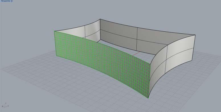
1 Copyright 2018, Chiu-Shui Chan. All Rights Reserved. Create regular features on façade and form: S206E057 Spring 2018 Modeling panel features or structural components could be done by a few components found in LunchBox, which is a GH plug-in for exploring mathematical shapes, paneling, structures, and workflow. Particularly, the panel patterns on surfaces could be created (by the panel functions) to serve as divided surface systems. The latest release of LunchBox is built to fit Grasshopper and Rhino 5.0, which could be found on This plugin includes the following tools, and detailed components are diagrammatically shown on the last page of this handout. 1. Generate: Components for cool generative geometry. 2. Math: Create parametric surfaces and forms such as the Mobius, Klein, or 3D Supershape 3. Panels: Create paneling systems such as quad grids, diamonds, or triangles. 4. Structure: Create wire structures such as diagrids or space trusses. 5. Utility: Rationalize spline curves and reverse surfaces. 6. Workflow: Read and write Excel files and automate baking and saving. Methods of installing LunchBox are the same as any plug-in installations. Here are the typical installation sequences, again, provided FYI. Download the ZIP package. In Grasshopper, choose File > Special Folders > Components folder. Save the LunchBox.gha file there. Right-click the file > Properties > make sure there is no "blocked" text Restart Rhino and Grasshopper, the LunchBox will appear as one of the tags in the tag area next to the Display tag. Example one: S206E Lecture 16, 4/27/2018, Rhino 3D, Grasshopper & Architecture Modeling Applications of LunchBox: 1. In Rhino, use Surface from a 3 or 4 corner points tool to generate a surface on front view. This surface shall be an untrimmed free surface. 2. In GH, apply a Surface component > Set One Surface and assign the surface to it. 3. From the LunchBox tag, apply the Staggered Quad Panel to generate the brick pattern on the face. 4. Define integer number sliders for U and V, which defines the number of staggered faces along X and Y axes. 5. Define Random Split List component, link the panel from Quad Staggered to the list of the Random Split List to see the randomly split surfaces of A and B. R on the Random Split List controls the randomization of the split which is defined by a slider for the number of seed to generate variations. S controls how many panels go to either A or B (or the proportion of the randomness for A and B). 6. To see the results of random split of the faces visually, use two Surface components and link the output of A & B to these two Surface components. 7. Then, Offset one or two of the faces to see the panel (or the brick pattern on façade). See the image A below which has the offset faces without thickness. 8. To make a solid from each group of surfaces, use Box Rectangle with a number slider to control the height for making boxes. Here, each surface has its rectangle which was created by Quad Staggered component. See the image B below. Page 1 (4/20/2018)


2 Images A: results with Offset component. Image B: results with Box Rectangle. The thickness of the brick could be increased or decreased to make different effects. Page 2 (4/20/2018)

3 Irregular features on façade and backward thinking: For irregular shape creation, methods used are different. Here is the example of modeling an irregular façade in Rhino through GH. 1. Create the façade first with Surface Creation > Surface from 3 or 4 corner points function in the Front Viewport. This surface plane represents one of the facades. 2. Use Polyline to draw the irregular shape inside this surface. 3. Use split to take the irregular shape away from the surface. 4. Erase the irregular shape away. 5. ExtrudeCrv > Select the entire shape> In the sub-function area, turn the solid: Yes, Deletinput: Yes, Extrusion distance: 3. Following the methods of modeling in Rhino, the steps of executing the modeling could be converted into algorithms. Here are two versions of algorithms. Executing the backward thinking through GH (Version one): 1. The first algorithm is to apply Extrude Linear (Extrude) component to extrude the shape into 3D solid. The Extrude Linear component needs the following four inputs. P is the profile curve or surface, which is the basic geometry. If it is curve input, then apply curves to construct the shape. If it is surface input, then apply surface tools to create the basic shape. Po indicates the orientation plane of the profile shape. A is the extrusion axis, which could be a drawn line represents the axis. Ao is the orientation plane for the axis to rest on. Its output is a BREP representation of the geometry. Page 3 (4/20/2018)

 and Geo (geometry) sit on the XZ planes and shall be extruded out from")
: The geometry of the axis could be represented by a line component, which are defined by two points and")


4 2. In this Extrude (Linear) component, the profile could take either a curve or a surface input. In this example, the original shape was created as a surface, so it is assigned to the Surface component for input. If it is a curve, then it might use Geometry as input format. (You could test if the BREP component could serve the input purpose.) 3. For the Po and Ao planes, it is defined and assigned as XZ Plane, because both objects of the Srf (surface) and Geo (geometry) sit on the XZ planes and shall be extruded out from it. 4. For the extrusion Axis, it could be a drawn line representing the axis and is assigned to the geometry parameter for serving the input for A component. The second version of backward thinking applied in GH (Version two): The geometry of the axis could be represented by a line component, which are defined by two points and controlled by six number sliders of x, y, z coordinates to make the change flexible. The 3D solid of the shape shall be created in either direction determined by positive or negative values. In this version two of the algorithm, the GH components applied for form generations are more completed and robust than version one. Question A: Could the final form created by the Extrude Linear Component be baked as Rhino model, saved as BREP geometry component and manipulated further? That relates to the notion of recursion which had been covered in lecture 11. An example is given in this handout. Question B: Could the entire creation of a building be implemented by GH? The answer is yes, but, it is not that efficient. Hybrid of Rhino and GH would be better. See the example below, which is the mixture of Rhino model and the GH components together with utilizing extra components provided by LunchBox plug-in. Page 4 (4/20/2018)


5 The LunchBox plug-in is able to do regular shape generation. For instance, the repetitive window openings in this example were done through Quad Panels component to create quadrangular panels on a surface in GH. There is a function of Path Mapper, which creates a data tree for the lexical data items. The way to change the lexical data format is executed by Lexer Combo Editor. Click on the icon to open the Lexer Editor. Inside the Editor, type {A;B;C;D} for the source and {A;B;C;D%2=0;D} for the target. The output of Path Mapper will be a part of the data tree input for Simplify Component. Page 5 (4/20/2018)


6 Page 6 (4/20/2018)


7 Coding example: Question: Could the final baked model be applied again through BREP and manipulated even further? This question relates to the concept of GH recursion versus form recursion, which could be found in the following example. Free form manipulation (or modification): This example is to create a cracked effect for a sculpture, which is shown on the following pictures. The sculpture has been modeled in Rhino as shown in the image on the right. This example is to apply a GH algorithm to create the special effects for the Rhino geometry, which could be converted into a Rhino model again. The algorithm is called BREP Cracking that could be found on food4rhino Web site. However, it was written in Chinese and couldn t find English translation. Here are the brief explanations of the algorithm applied and explained here for GH exercise reference. 1. The form is the geometry encoded in BREP parameter component in Grasshopper. 2. Through the HoopSnake iteration, edges of each cell are divided (or broken) 13 times to generate cracking effects along edges. HoopSnake is the recursive function. Its changing data (or Data input) was provided by the BREP Creaking component which was loaded from the Grasshopper User Group. Page 7 (4/20/2018)


8 3. The broken edges were joined through Join Curves component to make better results. 4. Finally, the entire form is defined as blue color through Color Swatch and displayed through Custom Preview to make a cyan color for the object. 5. The final form in Custom Preview could be baked into Rhino as a solid model. Here is the coding example of the cracking algorithm. Differences between the original image and the created final effects. Page 8 (4/20/2018)

9 Lists of the available LunchBox function components. This image of the LuncBox function components was adapted from the LunchBox web site and pasted here for the class information, Please take some time to explore their applications. Reminder: The due date of assignment #2 would be 3/28/2017. Page 9 (4/20/2018)
S206E Lecture 23, 5/26/2016, Interaction between Python and Grasshopper
 S206E057 -- Lecture 23, 5/26/2016, Interaction between Python and Grasshopper Copyright 2016, Chiu-Shui Chan. All Rights Reserved. S206E057 Spring 2016 This lecture covers the techniques of using rhinoscriptsyntax
S206E Lecture 17, 5/1/2018, Rhino & Grasshopper, Tower modeling
 S206E057 -- Lecture 17, 5/1/2018, Rhino & Grasshopper, Tower modeling Copyright 2018, Chiu-Shui Chan. All Rights Reserved. Concept of Morph in Rhino and Grasshopper: S206E057 Spring 2018 Morphing is a
S206E Lecture 13, 5/22/2016, Grasshopper Math and Logic Rules
 S206E057 -- Lecture 13, 5/22/2016, Grasshopper Math and Logic Rules Copyright 2016, Chiu-Shui Chan. All Rights Reserved. Interface of Math and Logic Functions 1. Basic mathematic operations: For example,
S206E Lecture 5, 5/18/2016, Importing and Tracing Drawing Information
 Copyright 2016, Chiu-Shui Chan. All Rights Reserved. S206E057 Spring 2016 2D information in the form of drawings can be brought into Rhino in two major ways. The first one is to import the actual digital
S206E Lecture 3, 5/15/2017, Rhino 2D drawing an overview
 Copyright 2017, Chiu-Shui Chan. All Rights Reserved. S206E057 Spring 2017 Rhino 2D drawing is very much the same as it is developed in AutoCAD. There are a lot of similarities in interface and in executing
S206E Lecture 15, 4/27/2018, Rhino 3D, Grasshopper, Shanghai Tower modeling
 S206E057 -- Lecture 15, 4/27/2018, Rhino 3D, Grasshopper, Shanghai Tower modeling Copyright 2018, Chiu-Shui Chan. All Rights Reserved. Creation of high-rise building models has a typical algorithm, which
RHINO SURFACE MAKING PART 1
 TUTORIAL 04: RHINO SURFACE MAKING PART 1 By Jeremy L Roh, Professor of Digital Methods I UNC Charlotte s School of Architecture Surfaces are a key component in shaping 3D objects within Rhinoceros. All
Exercise Guide. Published: August MecSoft Corpotation
 VisualCAD Exercise Guide Published: August 2018 MecSoft Corpotation Copyright 1998-2018 VisualCAD 2018 Exercise Guide by Mecsoft Corporation User Notes: Contents 2 Table of Contents About this Guide 4
SWITCHING FROM GRASSHOPPER TO VECTORWORKS
 SWITCHING FROM GRASSHOPPER TO VECTORWORKS INTRODUCTION Graphical scripting allows you to build a parametric process that is powerful and easier to use than traditional programming. Its flow chart-like
Oasys GSA. Getting Started
 Getting Started 13 Fitzroy Street London W1T 4BQ Telephone: +44 (0) 20 7755 3302 Facsimile: +44 (0) 20 7755 3720 Central Square Forth Street Newcastle Upon Tyne NE1 3PL Telephone: +44 (0) 191 238 7559
Lecture 4, 5/27/2017, Rhino Interface an overview
 數字建築與城市设计 Spring 2017 Lecture 4, 5/27/2017, Rhino Interface an overview Copyright 2017, Chiu-Shui Chan. All Rights Reserved. This lecture concentrates on the use of tools, 3D solid modeling and editing
Lesson 1 Parametric Modeling Fundamentals
 1-1 Lesson 1 Parametric Modeling Fundamentals Create Simple Parametric Models. Understand the Basic Parametric Modeling Process. Create and Profile Rough Sketches. Understand the "Shape before size" approach.
Chapter 2: Rhino Objects
 The fundamental geometric objects in Rhino are points, curves, surfaces, polysurfaces, extrusion objects, and polygon mesh objects. Why NURBS modeling NURBS (non-uniform rational B-splines) are mathematical
Structural & Thermal Analysis Using the ANSYS Workbench Release 12.1 Environment
 ANSYS Workbench Tutorial Structural & Thermal Analysis Using the ANSYS Workbench Release 12.1 Environment Kent L. Lawrence Mechanical and Aerospace Engineering University of Texas at Arlington SDC PUBLICATIONS
Parametric Modeling Design and Modeling 2011 Project Lead The Way, Inc.
 Parametric Modeling Design and Modeling 2011 Project Lead The Way, Inc. 3D Modeling Steps - Sketch Step 1 Sketch Geometry Sketch Geometry Line Sketch Tool 3D Modeling Steps - Constrain Step 1 Sketch Geometry
Weaverbird Tutorial - Mesh Tesselation and Extraction
 Weaverbird Tutorial - Mesh Tesselation and Extraction Darwin Alex Fowler Arch 486 - Spring - Johnson Plugin author - Giulio Piacentino The purpose of this tutorial is to deomonstrate a simple process to
3 AXIS STANDARD CAD. BobCAD-CAM Version 28 Training Workbook 3 Axis Standard CAD
 3 AXIS STANDARD CAD This tutorial explains how to create the CAD model for the Mill 3 Axis Standard demonstration file. The design process includes using the Shape Library and other wireframe functions
Module 1: Basics of Solids Modeling with SolidWorks
 Module 1: Basics of Solids Modeling with SolidWorks Introduction SolidWorks is the state of the art in computer-aided design (CAD). SolidWorks represents an object in a virtual environment just as it exists
Basic course. Grasshopper. Vicente Soler 2013/14 TOOLS TRAINING ESCUELA DE ARQUITECTURA UNIVERSIDAD EUROPEA
 Basic course Grasshopper Vicente Soler 2013/14 TOOLS TRAINING ESCUELA DE ARQUITECTURA UNIVERSIDAD EUROPEA Tools Training Grasshopper Course Escuela de Arquitectura Universidad Europea de Madrid C/ Tajo
Grasshopper Level 1 Class: Improving your workflow using parametric tools
 Grasshopper Level 1 Class: Improving your workflow using parametric tools Simply Rhino Limited 0208 498 9900 www.simplyrhino.co.uk training@simplyrhino.co.uk 1 Introduction Instructors: Arthur Mamou-Mani
Case Study 1: Piezoelectric Rectangular Plate
 Case Study 1: Piezoelectric Rectangular Plate PROBLEM - 3D Rectangular Plate, k31 Mode, PZT4, 40mm x 6mm x 1mm GOAL Evaluate the operation of a piezoelectric rectangular plate having electrodes in the
COMPUTER AIDED ARCHITECTURAL GRAPHICS FFD 201/Fall 2013 HAND OUT 1 : INTRODUCTION TO 3D
 COMPUTER AIDED ARCHITECTURAL GRAPHICS FFD 201/Fall 2013 INSTRUCTORS E-MAIL ADDRESS OFFICE HOURS Özgür Genca ozgurgenca@gmail.com part time Tuba Doğu tubadogu@gmail.com part time Şebnem Yanç Demirkan sebnem.demirkan@gmail.com
A Comprehensive Introduction to SolidWorks 2011
 A Comprehensive Introduction to SolidWorks 2011 Godfrey Onwubolu, Ph.D. SDC PUBLICATIONS www.sdcpublications.com Schroff Development Corporation Chapter 2 Geometric Construction Tools Objectives: When
AutoCAD 2009 Tutorial
 AutoCAD 2009 Tutorial Second Level: 3D Modeling Randy H. Shih Oregon Institute of Technology SDC PUBLICATIONS Schroff Development Corporation www.schroff.com Better Textbooks. Lower Prices. AutoCAD 2009
Tutorial Second Level
 AutoCAD 2018 Tutorial Second Level 3D Modeling Randy H. Shih SDC PUBLICATIONS Better Textbooks. Lower Prices. www.sdcpublications.com Powered by TCPDF (www.tcpdf.org) Visit the following websites to learn
TUTORIAL 07: RHINO STEREOTOMIC MODELING PART 2. By Jeremy L Roh, Professor of Digital Methods I UNC Charlotte s School of Architecture
 TUTORIAL 07: RHINO STEREOTOMIC MODELING PART 2 By Jeremy L Roh, Professor of Digital Methods I UNC Charlotte s School of Architecture This tutorial will explore the Stereotomic Modeling Methods within
Parametric Modeling. With. Autodesk Inventor. Randy H. Shih. Oregon Institute of Technology SDC PUBLICATIONS
 Parametric Modeling With Autodesk Inventor R10 Randy H. Shih Oregon Institute of Technology SDC PUBLICATIONS Schroff Development Corporation www.schroff.com www.schroff-europe.com 2-1 Chapter 2 Parametric
Autodesk Inventor 2019 and Engineering Graphics
 Autodesk Inventor 2019 and Engineering Graphics An Integrated Approach Randy H. Shih SDC PUBLICATIONS Better Textbooks. Lower Prices. www.sdcpublications.com Powered by TCPDF (www.tcpdf.org) Visit the
SOLIDWORKS: Lesson III Patterns & Mirrors. UCF Engineering
 SOLIDWORKS: Lesson III Patterns & Mirrors UCF Engineering Solidworks Review Last lesson we discussed several more features that can be added to models in order to increase their complexity. We are now
FREEFORM SURFACES WITH PLANAR QUADRILATERAL FACES
 FREEFORM SURFACES WITH PLANAR QUADRILATERAL FACES If you try to cover a freeform surface with quadrilateral faces, in general the quadrilateral faces are not planar, because their four vertices does not
CATIA V5 Parametric Surface Modeling
 CATIA V5 Parametric Surface Modeling Version 5 Release 16 A- 1 Toolbars in A B A. Wireframe: Create 3D curves / lines/ points/ plane B. Surfaces: Create surfaces C. Operations: Join surfaces, Split & Trim
RHINO; AN INTRODUCTION + FAKING TRABECULAE; EndOfLine.info;
 RHINO; AN INTRODUCTION + FAKING TRABECULAE; EndOfLine.info; Rhinoceros is a relatively simple program with an AUTOCAD based interface. The disadvantage of this type of interface is a series of terms need
Extrusion Revolve. ENGR 1182 SolidWorks 02
 Extrusion Revolve ENGR 1182 SolidWorks 02 Today s Objectives Creating 3D Shapes from 2D sketches using: Extrusion Revolve SW02 In-Class Activity Extrude a Camera Revolve a Wheel SW02 Out-of-Class Homework
The Christmas motives which served as a base for the cookie cutters.
 Seasonal 3D Printing 3D Printed Cookie Cutters (Part 2) As described in yesterday s blog post, cookiecaster.com is a neat and free service to create your own cookie cutters within minutes. However, the
SWITCHING FROM RHINO TO VECTORWORKS
 SWITCHING FROM RHINO TO VECTORWORKS INTRODUCTION There are a lot of 3D modeling software programs to choose from and each has its own strengths and weaknesses. For architects, flexibility and ease of use
Structural & Thermal Analysis using the ANSYS Workbench Release 11.0 Environment. Kent L. Lawrence
 ANSYS Workbench Tutorial Structural & Thermal Analysis using the ANSYS Workbench Release 11.0 Environment Kent L. Lawrence Mechanical and Aerospace Engineering University of Texas at Arlington SDC PUBLICATIONS
Module 4A: Creating the 3D Model of Right and Oblique Pyramids
 Inventor (5) Module 4A: 4A- 1 Module 4A: Creating the 3D Model of Right and Oblique Pyramids In Module 4A, we will learn how to create 3D solid models of right-axis and oblique-axis pyramid (regular or
Chapter 10. Creating 3D Objects Delmar, Cengage Learning
 Chapter 10 Creating 3D Objects 2011 Delmar, Cengage Learning Objectives Extrude objects Revolve objects Manipulate surface shading and lighting Map artwork to 3D objects Extrude Objects Extrude & Bevel
Table of contents 2 / 117
 1 / 117 Table of contents Welcome... 4 System requirements... 5 Getting help... 6 Commands... 7 Primitives... 10 Plane... 11 Box... 13 Torus... 15 Cylinder... 18 Sphere... 20 Ellipsoid... 22 Cone... 24
Autodesk Fusion 360: Model. Overview. Modeling techniques in Fusion 360
 Overview Modeling techniques in Fusion 360 Modeling in Fusion 360 is quite a different experience from how you would model in conventional history-based CAD software. Some users have expressed that it
Grade 6 Mathematics Item Specifications Florida Standards Assessments
 Content Standard MAFS.6.G Geometry MAFS.6.G.1 Solve real-world and mathematical problems involving area, surface area, and volume. Assessment Limits Calculator s Context A shape is shown. MAFS.6.G.1.1
Transformations in the Plane - Activity 1 Reflections in axes and an oblique line.
 Name: Class: p 5 Maths Helper Plus Resource Set. Copyright 00 Bruce A. Vaughan, Teachers Choice Software Transformations in the Plane - Activity Reflections in axes and an oblique line. ) On the diagram
Roadway Alignments and Profiles
 NOTES Module 15 Roadway Alignments and Profiles In this module, you learn how to create horizontal alignments, surface profiles, layout (design) profiles, and profile views in AutoCAD Civil 3D. This module
Dgp _ lecture 2. Curves
 Dgp _ lecture 2 Curves Questions? This lecture will be asking questions about curves, their Relationship to surfaces, and how they are used and controlled. Topics of discussion will be: Free form Curves
Equipment Support Structures
 Equipment Support Structures Overview Conventions What's New? Getting Started Setting Up Your Session Creating a Simple Structural Frame Creating Non-uniform Columns Creating Plates with Openings Bracing
Introduction to ANSYS DesignModeler
 Lecture 5 Modeling 14. 5 Release Introduction to ANSYS DesignModeler 2012 ANSYS, Inc. November 20, 2012 1 Release 14.5 Preprocessing Workflow Geometry Creation OR Geometry Import Geometry Operations Meshing
Equipment Support Structures
 Page 1 Equipment Support Structures Preface Using This Guide Where to Find More Information Conventions What's New? Getting Started Setting Up Your Session Creating a Simple Structural Frame Creating Non-uniform
AREA Judo Math Inc.
 AREA 2013 Judo Math Inc. 6 th grade Problem Solving Discipline: Black Belt Training Order of Mastery: Area 1. Area of triangles by composition 2. Area of quadrilaterals by decomposing 3. Draw polygons
Introduction to AutoCAD 2012
 Introduction to AutoCAD 2012 Alf Yarwood Chapter 13 Exercise 1 1. Open AutoCAD 2012 with a double-click on its shortcut icon in the Windows desktop. 2. Open the template acadiso3d.dwt. 3. Make two new
SWITCHING FROM SKETCHUP TO VECTORWORKS
 SWITCHING FROM SKETCHUP TO VECTORWORKS INTRODUCTION There are a lot of 3D modeling software programs to choose from and each has its own strengths and weaknesses. For architects, flexibility and ease of
Motional Design Allianz Arena 尉东颖
 Motional Design Allianz Arena 2015206051 尉东颖 CONTENT A. Introduction of the building B. General thingking of modeling methods Allianz Arena Designed by: HERZOG & DE MEURON Project location: Munich, Germany
Spring 2011 Workshop ESSENTIALS OF 3D MODELING IN RHINOCEROS February 10 th 2011 S.R. Crown Hall Lower Core Computer Lab
 [1] Open Rhinoceros. PART 1 INTRODUCTION [4] Click and hold on the Boundary Lines in where they form a crossing and Drag from TOP RIGHT to BOTTOM LEFT to enable only the PERSPECTIVE VIEW. [2] When the
Creating T-Spline Forms
 1 / 28 Goals 1. Create a T-Spline Primitive Form 2. Create a T-Spline Revolve Form 3. Create a T-Spline Sweep Form 4. Create a T-Spline Loft Form 2 / 28 Instructions Step 1: Go to the Sculpt workspace
Selective Space Structures Manual
 Selective Space Structures Manual February 2017 CONTENTS 1 Contents 1 Overview and Concept 4 1.1 General Concept........................... 4 1.2 Modules................................ 6 2 The 3S Generator
Det Teknisk-Naturvidenskabelige Fakultet Første Studieår AALBORG UNIVERSITET Arkitektur Og Design MATEMATIK OG FORM
 Det Teknisk-Naturvidenskabelige Fakultet Første Studieår AALBORG UNIVERSITET Arkitektur Og Design MATEMATIK OG FORM 5 March 2012 - Lecture GH2 (in English) Matrices and Transformations in Grasshopper Group
Autodesk Inventor - Basics Tutorial Exercise 1
 Autodesk Inventor - Basics Tutorial Exercise 1 Launch Inventor Professional 2015 1. Start a New part. Depending on how Inventor was installed, using this icon may get you an Inch or Metric file. To be
Adaptive Components Making Them Work For You. Chris Mawson Arup
 Adaptive Components Making Them Work For You Chris Mawson Arup Essential Viewing Visit the following websites for essential, awesome tips and tricks! Zach Kron s blog :- buildzblogsport.com David Light
3D AUTOCAD. The view we ve been working in is a top or plan view. From this view even a 3D drawing will appear 2D.
 3D AUTOCAD Thus far, we ve looked at tools and operations in 2D with work completed on only the X- and Y- axes. The axes symbol has been present on our screen but we haven t had much use for it. The view
Create a Rubber Duck. This tutorial shows you how to. Create simple surfaces. Rebuild a surface. Edit surface control points. Draw and project curves
 Page 1 of 24 Create a Rubber Duck This exercise focuses on the free form, squishy aspect. Unlike the flashlight model, the exact size and placement of the objects is not critical. The overall form is the
Solid Modeling: Part 1
 Solid Modeling: Part 1 Basics of Revolving, Extruding, and Boolean Operations Revolving Exercise: Stepped Shaft Start AutoCAD and use the solid.dwt template file to create a new drawing. Create the top
Computer Graphics Fundamentals. Jon Macey
 Computer Graphics Fundamentals Jon Macey jmacey@bournemouth.ac.uk http://nccastaff.bournemouth.ac.uk/jmacey/ 1 1 What is CG Fundamentals Looking at how Images (and Animations) are actually produced in
Licom Systems Ltd., Training Course Notes. 3D Surface Creation
 , Training Course Notes Work Volume and Work Planes...........................1 Overview..........................................1 Work Volume....................................1 Work Plane......................................1
3. Preprocessing of ABAQUS/CAE
 3.1 Create new model database 3. Preprocessing of ABAQUS/CAE A finite element analysis in ABAQUS/CAE starts from create new model database in the toolbar. Then save it with a name user defined. To build
Additional Exercises. You will perform the following exercises to practice the concepts learnt in this course:
 Additional Exercises You will perform the following exercises to practice the concepts learnt in this course: Master Exercise : Mobile Phone Plastic Bottle Exercise 1 Master Exercise : Mobile Phone In
The Rectangular Problem
 C h a p t e r 2 The Rectangular Problem In this chapter, you will cover the following to World Class standards: The tools for simple 2D Computer Aided Drafting (CAD) The Command Line and the Tray The Line
3DReshaper Help DReshaper Beginner's Guide. Surveying
 3DReshaper Beginner's Guide Surveying 1 of 29 Cross sections Exercise: Tunnel analysis Surface analysis Exercise: Complete analysis of a concrete floor Surveying extraction Exercise: Automatic extraction
Autodesk Inventor Design Exercise 2: F1 Team Challenge Car Developed by Tim Varner Synergis Technologies
 Autodesk Inventor Design Exercise 2: F1 Team Challenge Car Developed by Tim Varner Synergis Technologies Tim Varner - 2004 The Inventor User Interface Command Panel Lists the commands that are currently
BCC 3D Extruded Image Shatter Filter
 BCC 3D Extruded Image Shatter Filter 3D Extruded Image Shatter shatters the image in 3D space and disperses the image fragments. Unlike the 3D Image Shatter filter, this filter allows you to create threedimensional
TRAINING SESSION Q2 2016
 There are 8 main topics in this training session which focus on the Sketch tools in IRONCAD. Content Sketch... 2 3D Scene Background Settings... 3 Creating a new empty Sketch... 4 Foam with cut out for
Tutorial 4: Texture Mapping Techniques
 Tutorial 4: Texture Mapping Techniques Completion time 40 minutes In the previous tutorial we learned how to create materials, and how to assign texture maps to those materials. In this tutorial we will
The Villa Savoye ( ), Poisy, Paris.
, Poisy, Paris.") Learning SketchUp Villa Savoye This tutorial will involve modeling the Villa Savoye by Le Corbusier Files needed to complete this tutorial are available in Mr. Cochran s Web Site The Villa Savoye (1929-1931),
Learning SketchUp Villa Savoye This tutorial will involve modeling the Villa Savoye by Le Corbusier Files needed to complete this tutorial are available in Mr. Cochran s Web Site The Villa Savoye (1929-1931),
Autodesk Fusion 360 Training: The Future of Making Things Attendee Guide
 Autodesk Fusion 360 Training: The Future of Making Things Attendee Guide Abstract After completing this workshop, you will have a basic understanding of editing 3D models using Autodesk Fusion 360 TM to
TRINITAS. a Finite Element stand-alone tool for Conceptual design, Optimization and General finite element analysis. Introductional Manual
 TRINITAS a Finite Element stand-alone tool for Conceptual design, Optimization and General finite element analysis Introductional Manual Bo Torstenfelt Contents 1 Introduction 1 2 Starting the Program
GRASSHOPPER TUTORIAL 02 PERFORATED CURVATURE.
 GRASSHOPPER TUTORIAL 02 PERFORATED CURVATURE www.exlab.org IDEA PERFORATED CURVATURE THIS TUTORIAL EXTENDS UPON TUTORIAL 01 BY CREATING A SIMPLE DEFINITION THAT ANALYSES THE CURVATURE OF A DOUBLY CURVED
COMPUTER AIDED DESIGN CURRICULLOM RHINO BASED 3D DESIGN
 COMPUTER AIDED DESIGN CURRICULLOM RHINO BASED 3D DESIGN S.no. CONTENTS Page no S. no. CONTENTS PAGE no. 1. Introduction 1 2. Necessary of Rhino in Designing 2 3. Working with 3D Models 3 4. Object Types
CS 465 Program 4: Modeller
 CS 465 Program 4: Modeller out: 30 October 2004 due: 16 November 2004 1 Introduction In this assignment you will work on a simple 3D modelling system that uses simple primitives and curved surfaces organized
Chapter 12: Pull Toy - Solids and Transforms
 This tutorial demonstrates using solid primitives and simple transforms. You will learn how to: Enter coordinates to place points exactly. Draw a free-form curve and polygon. Create a pipe along a curve.
The Dark Arts of Revit: Conceptual Modeling Tools and Computational Logic in Structural Design
 Session 3 The Dark Arts of Revit: Conceptual Modeling Tools and Computational Logic in Structural Design hvasshaug@gmail.com Class Description Revit software provides tools for using conceptual modeling
Module 5: Creating Sheet Metal Transition Piece Between a Square Tube and a Rectangular Tube with Triangulation
 1 Module 5: Creating Sheet Metal Transition Piece Between a Square Tube and a Rectangular Tube with Triangulation In Module 5, we will learn how to create a 3D folded model of a sheet metal transition
Autodesk Conceptual Design Curriculum 2011 Student Workbook Unit 2: Parametric Exploration Lesson 1: Parametric Modeling
 Autodesk Conceptual Design Curriculum 2011 Student Workbook Unit 2: Parametric Exploration Lesson 1: Parametric Modeling Overview: Parametric Modeling In this lesson, you learn the basic principles of
Lesson 14 Blends. For Resources go to > click on the Creo Parametric 2.0 Book cover
 Lesson 14 Blends Figure 14.1 Cap OBJECTIVES Create a Parallel Blend feature Use the Shell Tool Create a Hole Pattern REFERENCES AND RESOURCES For Resources go to www.cad-resources.com > click on the Creo
Parametric Modeling with UGS NX 4
 Parametric Modeling with UGS NX 4 Randy H. Shih Oregon Institute of Technology SDC PUBLICATIONS Schroff Development Corporation www.schroff.com www.schroff-europe.com 2-1 Chapter 2 Parametric Modeling
To start, open or build a simple solid model. The bracket from a previous exercise will be used for demonstration purposes.
 Render, Lights, and Shadows The Render programs are techniques using surface shading, surface tones, and surface materials that are then presented in a scene with options for lights and shadows. Modifications
SketchUp Tool Basics
 SketchUp Tool Basics Open SketchUp Click the Start Button Click All Programs Open SketchUp Scroll Down to the SketchUp 2013 folder Click on the folder to open. Click on SketchUp. Set Up SketchUp (look
Lesson 1: Creating T- Spline Forms. In Samples section of your Data Panel, browse to: Fusion 101 Training > 03 Sculpt > 03_Sculpting_Introduction.
 3.1: Sculpting Sculpting in Fusion 360 allows for the intuitive freeform creation of organic solid bodies and surfaces by leveraging the T- Splines technology. In the Sculpt Workspace, you can rapidly
Complex Shapes Creation with Hybrid Modelling
 Complex Shapes Creation with Hybrid Modelling Peter De Strijker Technical Sales Executive MFG - Benelux Our Customer s Industries Discrete product manufacture Agenda Quality Analyses of sketches and surfaces
QUICK-START TUTORIALS
 PUERMC02_0132276593.QXD 08/09/2006 06:05 PM Page 83 QUICK-START TUTORIALS Chapter Objectives Create two real 3D modeling projects, starting them from scratch. Know the difference between representing 3D
Lesson: Lightweighting of Robot Gripper Arm
 Lesson: Lightweighting of Robot Gripper Arm This functionality is only available in Fusion 360 Ultimate. In this exercise we'll perform a Shape Optimization study to reduce the weight of a robot gripper
More Practical Dynamo: Practical Uses for Dynamo Within Revit
 AS10613 & AS13937 More Practical Dynamo: Practical Uses for Dynamo Within Revit MARCELLO SGAMBELLURI, BIM DIRECTOR JOHN A. MARTIN & ASSOCIATES Learning Objectives Learn how to program using visual programming.
Year 2 Spring Term Week 5 to 7 - Geometry: Properties of Shape
 1 Year 2 Spring Term Week 5 to 7 - Geometry: Properties of Shape Recognise 2-D and 3-D shapes Count sides on 2-D shapes Count vertices on 2-D shapes Draw 2-D shapes Lines of symmetry Sort 2-D shapes Make
3D Modeler Creating Custom myhouse Symbols
 3D Modeler Creating Custom myhouse Symbols myhouse includes a large number of predrawn symbols. For most designs and floorplans, these should be sufficient. For plans that require that special table, bed,
SAMPLE. Table of Contents. Introduction... iii. How to Use this Manual... iv. 1.0 Simple 3D Modeling Architectural Modeling...
 Table of Contents Introduction... iii How to Use this Manual... iv 1.0 Simple 3D Modeling...1 1.1 Extrusions...1 1.2 Multiple Extrude...7 1.3 Simple Cafe Table...13 1.4 Setting 3D Views...19 1.5 Simple
3D ModelingChapter1: Chapter. Objectives
 Chapter 1 3D ModelingChapter1: The lessons covered in this chapter familiarize you with 3D modeling and how you view your designs as you create them. You also learn the coordinate system and how you can
The figures below are all prisms. The bases of these prisms are shaded, and the height (altitude) of each prism marked by a dashed line:
 of each prism marked by a dashed line:") Prisms Most of the solids you ll see on the Math IIC test are prisms or variations on prisms. A prism is defined as a geometric solid with two congruent bases that lie in parallel planes. You can create
Prisms Most of the solids you ll see on the Math IIC test are prisms or variations on prisms. A prism is defined as a geometric solid with two congruent bases that lie in parallel planes. You can create
Polygons in the Coordinate Plane
 Polygons in the Coordinate Plane LAUNCH (8 MIN) Before How can you find the perimeter of the sandbox that the park worker made? During How will you determine whether the park worker s plan for the sandbox
SWITCHING FROM GRASSHOPPER TO VECTORWORKS
 SWITCHING FROM GRASSHOPPER TO VECTORWORKS HOW TO PLACE A MARIONETTE NODE To use the Marionette tool in Vectorworks, you don t need to load a plug-in or work in a separate interface. The Marionette tool
Introducing Activstudio
 Introducing Activstudio Version 3 COPYRIGHT INFORMATION Introducing Activstudio Version 3 Copyright 2007 Promethean Limited. All rights reserved. If this guide is distributed with Activstudio software,
Mechanical Design V5R19 Update
 CATIA V5 Training Foils Mechanical Design V5R19 Update Version 5 Release 19 August 2008 EDU_CAT_EN_MD2_UF_V5R19 1 About this course Objectives of the course Upon completion of this course you will be able
and its Interfaces 2016 / 1 Interfaces
 and its Interfaces 2016 / 1 Interfaces Interfaces Graphical Interfaces SOFiPLUS-(X) AutoCAD FEA Extensions Revit Rhino Rhinoceros by Robert McNeel & Associates IFC Industry Foundation Classes Numerical
Solidworks 2006 Surface-modeling
 Solidworks 2006 Surface-modeling (Tutorial 2-Mouse) Surface-modeling Solid-modeling A- 1 Assembly Design Design with a Master Model Surface-modeling Tutorial 2A Import 2D outline drawing into Solidworks2006