RHINO SURFACE MAKING PART 1
|
|
|
- Lindsay Porter
- 5 years ago
- Views:
Transcription
1 TUTORIAL 04: RHINO SURFACE MAKING PART 1 By Jeremy L Roh, Professor of Digital Methods I UNC Charlotte s School of Architecture
2 Surfaces are a key component in shaping 3D objects within Rhinoceros. All 3D objects are made up of surfaces. Surfaces are generally derived by 2D curves (lines). Surfaces can be extended, trimmed, blended, connected, joined, etc. This tutorial will use the toolbar flyouts: Surface, Surface Tools, Curve Tools, and Curve From Object as pictured here.

3 2 3 Surfaces can be created by choosing 3 or 4 points. In this case, the points will be determined by snapping to the end points and intersections of 2D lines already drawn (points 1, 2, 3, and 4). 4 1
4
 that will define the surface")
5 Intricate surface shapes can be created by first selecting all of the 2D curves (lines) that will define the surface shape.
6 Sometimes it is necessary to temporarily separate construction items away from the model area in order to work on the piece. In this case, the curves (lines) that have been previously selected have been copied 50 to the left. It was specified to copy these items 50 so that when the operation is finished, it can be moved back 50 to the original location.
7 Since all of these curves (lines) are separate items, they need to be joined and trimmed to make a closed shape. Using the Connect tool from the Extend Curve toolbar flyout, just about all of the lines can be trimmed and extended with this one command.
8 The last part of the shape needs a line physically drawn to close the shape.
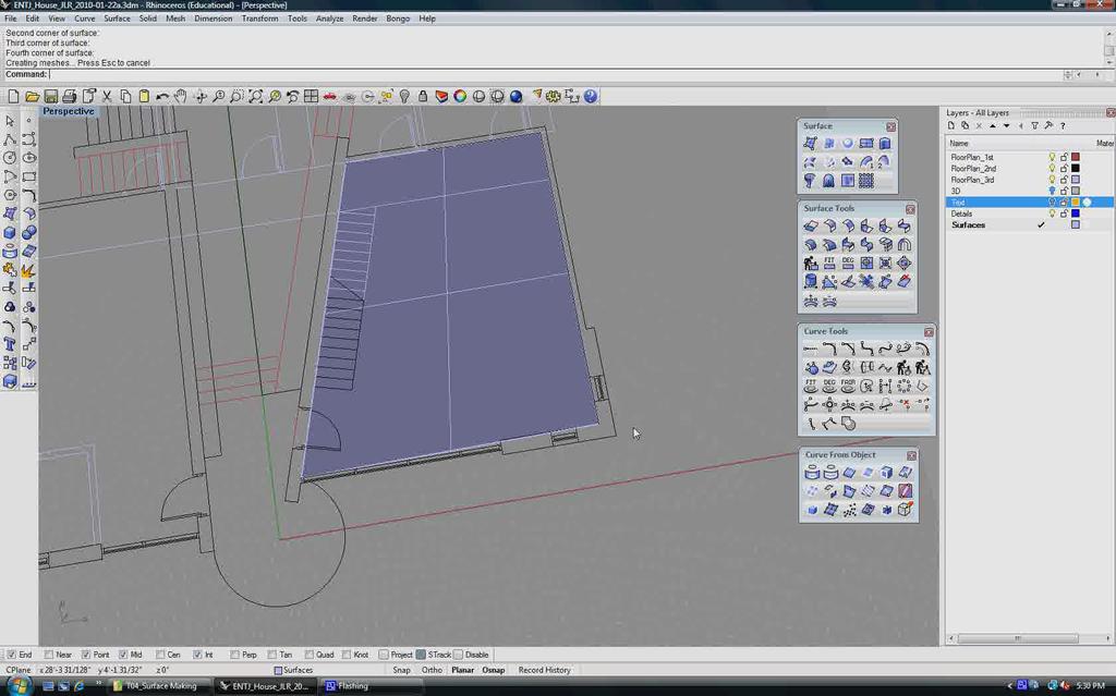
9 Select all of the curves (lines) that were just cleaned up and then select Join to make the intricate shape a closed planar curve.
10 With the closed planar curves selected, select the Surface from Planar Curves icon and the area inside the intricate shape is filled with a surface.
11 Move the shape to the right 50 to put it back in its original place.
12

13 Surfaces can be created from edge curves already drawn or associated with other surfaces/ polysurfaces. Select the Surface from 2, 3, or 4 Edge Curves icon.
14 Select curves (lines) that will define the boundary of the surface (1, 2, 3, and 4).
15 A surface is created that best fits within the boundary of the 4 curves selected; even though, one of the curves (3 on the previous screen) extended beyond the boundary.
16 1 2 Surfaces can be created by just drawing a rectangle using the Rectangular Plane: Corner to Corner command. Select the first point of the corner (1) and then the other point of the corner (2).
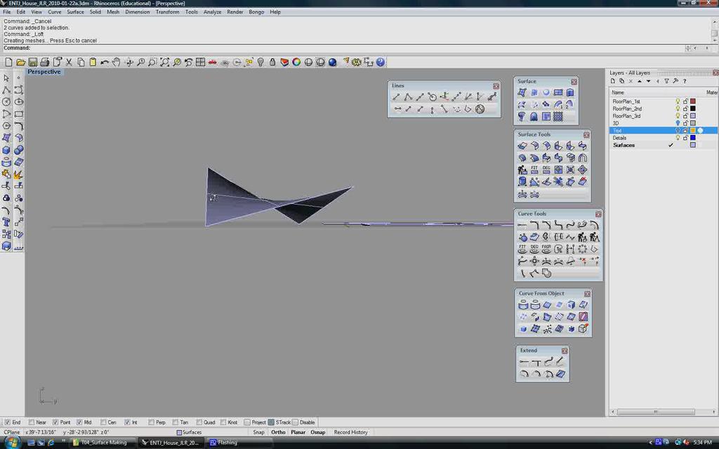
17 The next set of slides illustrates how to use the Loft command. First draw two lines that are a distance apart from one another and exist in space along the x, y, and z axis different from one another. Reference the next 6 slides.
18
19
20
21
22
23
24 1 Once the lines are drawn, select the Loft command and then select the lines in the order in which you want the surface to pass through (1 and 2) and then press Enter on the keyboard. The order isn t as important when there are only 2 lines; however, as you loft through a series of lines, it becomes very important that you specify the correct order. 2
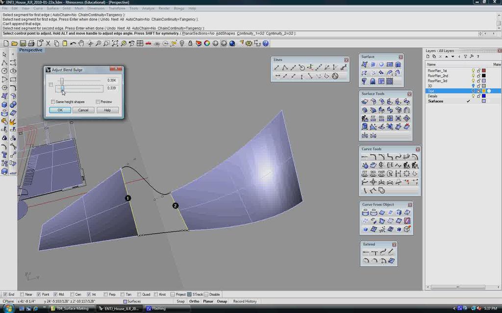
25 Once you press Enter, a pop-up dialog box will appear that allows you to specify ways in which the surface should be interpolated. Styles from Loose to Tight and simplification methods are available. In upcoming tutorials, we will go into the use of these options in more detail. For now, press OK.
26 A surface is created by interpolating all of the points inbetween the specified lines.
27
, and then press Enter")
28 2 1 Another example of lofting a surface; however, this example uses 3 lines. Select the Loft icon, then select the 3 curves in order (1, 2, and 3), and then press Enter on the keyboard. 3
29
30 A surface is created by interpolating all of the points inbetween the specified lines.
31 Another method to connect two surfaces is to use the Blend Surface tool. Left mouse-click on the icon.
32 Select the first edge (1) and then the second edge (2) of the surfaces that you wish to blend/ connect. 1 2
33 A pop-up dialog box appears that has two slider bars available. The sliders allow you to choose how to create the blend between surfaces. The next few slides illustrate the effects of the slider bar positions and the resulting black line previews. The black lines and points show the proposed blend based on the choices made with the slider positions.
34
35
36
37
38
39
40
41 Check the Preview option to see the proposed surface filled inbetween the black lines. Now when you move the slider bars, you can visually see the proposed surface manipulate in realtime. The next few slides show some examples.
42
43
44
45
46
47
48 Once surfaces are created, you can trim and edit them using Curve From Object, Extrude Straight, and the Trim tools. In this example, select the Circle icon After the blend operation is complete, a new surface is created. The original surfaces and the new surface remain as separate entities (1, 2, and 3). Later in this tutorial, the same number notation for these surfaces will be used to explain trimmed and untrimmed surfaces.
49 Draw a circle in plan view over the surfaces.
50 Make sure that the circle is noticeably above the surfaces. In this example, the circle looks very close to the surface. Select the circle.
51 Move the circle noticeably above the surfaces.
52 Step 2: Select the curve to project. In this case, the curve to project is the circle. Step 1: Select the Project to Surface icon.

53 Step 3: Select surfaces to project onto.
54 The circle is projected onto the surfaces.
55 Now that the circle is exactly on the surfaces, we can use the circle as a cutting object and trim the surfaces using the Trim command. Step 1: Select the Trim command. Step 2: Select the cutting object and press Enter on the keyboard. Step 3: Select the objects to trim and press Enter on the keyboard when the operation is complete. See the next few slides for the results.
56
57
58 Surfaces can be trimmed by using a Line that is extruded through the surface and used as the cutting object. Draw a line in the top view the noticeably overlaps the surface.
59 While the line is selected, left mouse-click on the Extrude Straight tool.

60 Make sure that the extrusion option is set to BothSides=Yes. Extrude the line so that the extrusion noticeably passes through the surface you eventually wish to trim.
61 Step 1: Select the Trim command. Step 3: Select the object to trim and press Enter on the Keyboard. Step 2: Select the cutting object and press Enter on the keyboard.
62 3 2 1 As a result of the last set of trim operations performed, the three surfaces (1, 2, and 3) are now identified as different types of surfaces: trimmed and untrimmed. Surface 1 has not been trimmed and still remains in its original created state; thus, this surfaces is referred to as an Untrimmed Surface. Surfaces 2 and 3 have been manipulated by previous trim commands; therefore, these surfaces are now referred to as Trimmed Surfaces.
63 Trimmed Surfaces can be untrimmed to restore the surface back to its original created state. This function can happen at anytime throughout the modeling process. Step 2: Select the edge of the surface to untrim. Step 1: Right mouseclick on the Trim icon to select the Untrim Surface tool.
64 Notice the edge with the trimmed circle still remains trimmed. The surface is untrimmed on the edge that was selected. Note: The next slide starts out by undoing this operation so that the surface form is back to its trimmed state.
65 3 2 1 Reference: Surface 1 = Untrimmed Surface Surface 2 = Trimmed Surface Surface 3 = Trimmed Surface
66 Surfaces can be extended by a specified distance; however, you need to know whether or not the surface is an Untrimmed or Trimmed Surface. Step 1: Left mouse-click on the Extend Untrimmed Surface icon. Step 2: Select the edge of the surface to extend.
67 Step 3: Type in a distance and press Enter on the keyboard. Normal V U U The surface edge is extended. This command determines the flow and form of the extension by interpolating the directional U-V-Normal data embedded in the makeup of the original surface. V Note: All surfaces and polysurfaces are made up of three directions: U, V, and Normal. You can think of these directions as corresponding to the X, Y, and Z Axis.
68 Step 1: Right mouse-click on the Extend Trimmed Surface icon. Step 2: Select the edge of the surface to extend.
69 Step 3: Type in a distance and press Enter on the keyboard.
70 The surface edge is extended.
TUTORIAL 07: RHINO STEREOTOMIC MODELING PART 2. By Jeremy L Roh, Professor of Digital Methods I UNC Charlotte s School of Architecture
 TUTORIAL 07: RHINO STEREOTOMIC MODELING PART 2 By Jeremy L Roh, Professor of Digital Methods I UNC Charlotte s School of Architecture This tutorial will explore the Stereotomic Modeling Methods within
TUTORIAL 03: RHINO DRAWING & ORGANIZATIONAL AIDS. By Jeremy L Roh, Professor of Digital Methods I UNC Charlotte s School of Architecture
 TUTORIAL 03: RHINO DRAWING & ORGANIZATIONAL AIDS By Jeremy L Roh, Professor of Digital Methods I UNC Charlotte s School of Architecture Modeling in 3D requires the use of various drawing and organizational
Chapter 6: Create Surfaces from Curves
 A common way of working in 3-D is to draw curves that represent edges, profiles, cross-sections, or other surface features and then to use surfacing commands to create surfaces from those curves. Edge
3D Design with 123D Design
 3D Design with 123D Design Introduction: 3D Design involves thinking and creating in 3 dimensions. x, y and z axis Working with 123D Design 123D Design is a 3D design software package from Autodesk. A
Lesson 1 Parametric Modeling Fundamentals
 1-1 Lesson 1 Parametric Modeling Fundamentals Create Simple Parametric Models. Understand the Basic Parametric Modeling Process. Create and Profile Rough Sketches. Understand the "Shape before size" approach.
Create a Rubber Duck. This tutorial shows you how to. Create simple surfaces. Rebuild a surface. Edit surface control points. Draw and project curves
 Page 1 of 24 Create a Rubber Duck This exercise focuses on the free form, squishy aspect. Unlike the flashlight model, the exact size and placement of the objects is not critical. The overall form is the
Additional Surface Tools
 Additional Surface Tools Several additional surface tools, techniques, and related functions are available. This supplement provides a brief introduction to those functions. Panel Part Features Replace
TUTORIAL 01: RHINO INTERFACE. By Jeremy L Roh, Professor of Digital Methods I UNC Charlotte s School of Architecture
 TUTORIAL 01: RHINO INTERFACE By Jeremy L Roh, Professor of Digital Methods I UNC Charlotte s School of Architecture Upon opening Rhinoceros 4.0, a Startup Template Dialog Box will appear. Left-click on
TRAINING SESSION Q2 2016
 There are 8 main topics in this training session which focus on the Sketch tools in IRONCAD. Content Sketch... 2 3D Scene Background Settings... 3 Creating a new empty Sketch... 4 Foam with cut out for
Modeling a Gear Standard Tools, Surface Tools Solid Tool View, Trackball, Show-Hide Snaps Window 1-1
 Modeling a Gear This tutorial describes how to create a toothed gear. It combines using wireframe, solid, and surface modeling together to create a part. The model was created in standard units. To begin,
Exercise Guide. Published: August MecSoft Corpotation
 VisualCAD Exercise Guide Published: August 2018 MecSoft Corpotation Copyright 1998-2018 VisualCAD 2018 Exercise Guide by Mecsoft Corporation User Notes: Contents 2 Table of Contents About this Guide 4
RHINO; AN INTRODUCTION + FAKING TRABECULAE; EndOfLine.info;
 RHINO; AN INTRODUCTION + FAKING TRABECULAE; EndOfLine.info; Rhinoceros is a relatively simple program with an AUTOCAD based interface. The disadvantage of this type of interface is a series of terms need
Chapter 16: Boat Hull - Loft and Sweep
 This tutorial demonstrates classic boat hull lofting techniques using typical plan and profile curves. The classic hull shape is based on a design from an old Boat Builder s Handbook magazine. Many designs
Parametric Modeling. With. Autodesk Inventor. Randy H. Shih. Oregon Institute of Technology SDC PUBLICATIONS
 Parametric Modeling With Autodesk Inventor R10 Randy H. Shih Oregon Institute of Technology SDC PUBLICATIONS Schroff Development Corporation www.schroff.com www.schroff-europe.com 2-1 Chapter 2 Parametric
Drawing Tools. Drawing a Rectangle
 Chapter Microsoft Word provides extensive DRAWING TOOLS that allow you to enhance the appearance of your documents. You can use these tools to assist in the creation of detailed publications, newsletters,
Spring 2011 Workshop ESSENTIALS OF 3D MODELING IN RHINOCEROS February 10 th 2011 S.R. Crown Hall Lower Core Computer Lab
 [1] Open Rhinoceros. PART 1 INTRODUCTION [4] Click and hold on the Boundary Lines in where they form a crossing and Drag from TOP RIGHT to BOTTOM LEFT to enable only the PERSPECTIVE VIEW. [2] When the
REVIT - NONCEILING BASED LIGHTS
 TUTORIAL C-29C: REVIT - NONCEILING BASED LIGHTS This Tutorial explains how to create your own light fixture that can be placed anywhere. Most lights in Revit are ceiling based/hosted meaning that you have
Modeling a Computer Mouse in Rhino File: mouse.3dm
 Tips Modeling a Computer Mouse in Rhino File: mouse.3dm www.pivot.no Copyright 2008 Pivot Produktdesign. Making digital or printed copies for non-commercial use is allowed. 1 In this tutorial you will
CHAPTER 1 COPYRIGHTED MATERIAL. Getting to Know AutoCAD. Opening a new drawing. Getting familiar with the AutoCAD and AutoCAD LT Graphics windows
 CHAPTER 1 Getting to Know AutoCAD Opening a new drawing Getting familiar with the AutoCAD and AutoCAD LT Graphics windows Modifying the display Displaying and arranging toolbars COPYRIGHTED MATERIAL 2
SOLIDWORKS: Lesson III Patterns & Mirrors. UCF Engineering
 SOLIDWORKS: Lesson III Patterns & Mirrors UCF Engineering Solidworks Review Last lesson we discussed several more features that can be added to models in order to increase their complexity. We are now
The Rectangular Problem
 C h a p t e r 2 The Rectangular Problem In this chapter, you will cover the following to World Class standards: The tools for simple 2D Computer Aided Drafting (CAD) The Command Line and the Tray The Line
Module 1: Basics of Solids Modeling with SolidWorks
 Module 1: Basics of Solids Modeling with SolidWorks Introduction SolidWorks is the state of the art in computer-aided design (CAD). SolidWorks represents an object in a virtual environment just as it exists
S206E Lecture 3, 5/15/2017, Rhino 2D drawing an overview
 Copyright 2017, Chiu-Shui Chan. All Rights Reserved. S206E057 Spring 2017 Rhino 2D drawing is very much the same as it is developed in AutoCAD. There are a lot of similarities in interface and in executing
Learning Rhino 3D. Modelling a fork
 > Background images - use PictureFrame command to load top and side images of the fork. Place the top image in the Top viewport and place the side image in the Front viewport. > Scale images - you will
Generating Vectors Overview
 Generating Vectors Overview Vectors are mathematically defined shapes consisting of a series of points (nodes), which are connected by lines, arcs or curves (spans) to form the overall shape. Vectors can
ILLUSTRATOR TUTORIAL-1 workshop handout
 Why is Illustrator a powerful tool? ILLUSTRATOR TUTORIAL-1 workshop handout Computer graphics fall into two main categories, bitmap graphics and vector graphics. Adobe Illustrator is a vector based software
Technique or Feature Where Introduced
 Part 6: Keypad 4 Mirrored features Patterned features First extrusion Rounded corners In the earpiece part, you defined a radial pattern, one that created new instances of a feature at intervals around
Inventor 201. Work Planes, Features & Constraints: Advanced part features and constraints
 Work Planes, Features & Constraints: 1. Select the Work Plane feature tool, move the cursor to the rim of the base so that inside and outside edges are highlighted and click once on the bottom rim of the
Tutorial Second Level
 AutoCAD 2018 Tutorial Second Level 3D Modeling Randy H. Shih SDC PUBLICATIONS Better Textbooks. Lower Prices. www.sdcpublications.com Powered by TCPDF (www.tcpdf.org) Visit the following websites to learn
Module 4A: Creating the 3D Model of Right and Oblique Pyramids
 Inventor (5) Module 4A: 4A- 1 Module 4A: Creating the 3D Model of Right and Oblique Pyramids In Module 4A, we will learn how to create 3D solid models of right-axis and oblique-axis pyramid (regular or
CATIA V5 Parametric Surface Modeling
 CATIA V5 Parametric Surface Modeling Version 5 Release 16 A- 1 Toolbars in A B A. Wireframe: Create 3D curves / lines/ points/ plane B. Surfaces: Create surfaces C. Operations: Join surfaces, Split & Trim
SOLIDWORKS 2016: A Power Guide for Beginners and Intermediate Users
 SOLIDWORKS 2016: A Power Guide for Beginners and Intermediate Users The premium provider of learning products and solutions www.cadartifex.com Table of Contents Dedication... 3 Preface... 15 Part 1. Introducing
TUTORIAL 2. OBJECTIVE: Use SolidWorks/COSMOS to model and analyze a cattle gate bracket that is subjected to a force of 100,000 lbs.
 TUTORIAL 2 OBJECTIVE: Use SolidWorks/COSMOS to model and analyze a cattle gate bracket that is subjected to a force of 100,000 lbs. GETTING STARTED: 1. Open the SolidWorks program. 2. Open a new part file.
Feature-Based Modeling and Optional Advanced Modeling. ENGR 1182 SolidWorks 05
 Feature-Based Modeling and Optional Advanced Modeling ENGR 1182 SolidWorks 05 Today s Objectives Feature-Based Modeling (comprised of 2 sections as shown below) 1. Breaking it down into features Creating
3 AXIS STANDARD CAD. BobCAD-CAM Version 28 Training Workbook 3 Axis Standard CAD
 3 AXIS STANDARD CAD This tutorial explains how to create the CAD model for the Mill 3 Axis Standard demonstration file. The design process includes using the Shape Library and other wireframe functions
Autodesk Inventor 2019 and Engineering Graphics
 Autodesk Inventor 2019 and Engineering Graphics An Integrated Approach Randy H. Shih SDC PUBLICATIONS Better Textbooks. Lower Prices. www.sdcpublications.com Powered by TCPDF (www.tcpdf.org) Visit the
Autodesk Inventor Design Exercise 2: F1 Team Challenge Car Developed by Tim Varner Synergis Technologies
 Autodesk Inventor Design Exercise 2: F1 Team Challenge Car Developed by Tim Varner Synergis Technologies Tim Varner - 2004 The Inventor User Interface Command Panel Lists the commands that are currently
Shape and Line Tools. tip: Some drawing techniques are so much easier if you use a pressuresensitive
 4Drawing with Shape and Line Tools Illustrator provides tools for easily creating lines and shapes. Drawing with shapes (rectangles, ellipses, stars, etc.) can be a surprisingly creative and satisfying
Tower Drawing. Learning how to combine shapes and lines
 Tower Drawing Learning how to combine shapes and lines 1) Go to Layout > Page Background. In the Options menu choose Solid and Ghost Green for a background color. This changes your workspace background
Paint Tutorial (Project #14a)
") Paint Tutorial (Project #14a) In order to learn all there is to know about this drawing program, go through the Microsoft Tutorial (below). (Do not save this to your folder.) Practice using the different
Paint Tutorial (Project #14a) In order to learn all there is to know about this drawing program, go through the Microsoft Tutorial (below). (Do not save this to your folder.) Practice using the different
3D AUTOCAD. The view we ve been working in is a top or plan view. From this view even a 3D drawing will appear 2D.
 3D AUTOCAD Thus far, we ve looked at tools and operations in 2D with work completed on only the X- and Y- axes. The axes symbol has been present on our screen but we haven t had much use for it. The view
Lesson 5 Solid Modeling - Constructive Solid Geometry
 AutoCAD 2000i Tutorial 5-1 Lesson 5 Solid Modeling - Constructive Solid Geometry Understand the Constructive Solid Geometry Concept. Create a Binary Tree. Understand the basic Boolean Operations. Create
Chapter 2: Rhino Objects
 The fundamental geometric objects in Rhino are points, curves, surfaces, polysurfaces, extrusion objects, and polygon mesh objects. Why NURBS modeling NURBS (non-uniform rational B-splines) are mathematical
Autodesk Inventor - Basics Tutorial Exercise 1
 Autodesk Inventor - Basics Tutorial Exercise 1 Launch Inventor Professional 2015 1. Start a New part. Depending on how Inventor was installed, using this icon may get you an Inch or Metric file. To be
Editing Polygons. Adding material/volume: Extrude. Learning objectives
 Learning objectives Be able to: use the Extrude tool to add volume to a polygon know what edge loops are and how to insert edge loops in a polygon cut edges in a polygon know multiple methods of sewing
Standard Toolbar. Main Toolbar. Page Sorter. Action Toolbar
 TEAMBOARD DRAW This is an annotation software that can be used with the interactive pen to write or draw on the projection surface. This software also provides advanced tools for saving and editing annotations
Autodesk Fusion 360: Model. Overview. Modeling techniques in Fusion 360
 Overview Modeling techniques in Fusion 360 Modeling in Fusion 360 is quite a different experience from how you would model in conventional history-based CAD software. Some users have expressed that it
SOLIDWORKS: Lesson 1 - Basics and Modeling. UCF Engineering
 SOLIDWORKS: Lesson 1 - Basics and Modeling Fundamentals UCF Engineering SolidWorks SolidWorks is a 3D solid modeling package which allows users to develop full solid models in a simulated environment for
Rhinoceros Car Modeling Tutorial
 Rhinoceros Car Modeling Tutorial This tutorial will guide you to car nurbs modeling process using Rhinoceros 3.0. To start a car modeling you will need some car images (or sketches) to get an idea of the
Google SketchUp. and SketchUp Pro 7. The book you need to succeed! CD-ROM Included! Kelly L. Murdock. Master SketchUp Pro 7 s tools and features
 CD-ROM Included! Free version of Google SketchUp 7 Trial version of Google SketchUp Pro 7 Chapter example files from the book Kelly L. Murdock Google SketchUp and SketchUp Pro 7 Master SketchUp Pro 7 s
Parametric Modeling Design and Modeling 2011 Project Lead The Way, Inc.
 Parametric Modeling Design and Modeling 2011 Project Lead The Way, Inc. 3D Modeling Steps - Sketch Step 1 Sketch Geometry Sketch Geometry Line Sketch Tool 3D Modeling Steps - Constrain Step 1 Sketch Geometry
Module 1B: Parallel-Line Flat Pattern Development of Sheet- Metal Folded Model Wrapping the 3D Space of A Truncated Right Prism
 Inventor (5) Module 1B: 1B- 1 Module 1B: Parallel-Line Flat Pattern Development of Sheet- Metal Folded Model Wrapping the 3D Space of A Truncated Right Prism In this Module, we will learn how to create
XPEL DAP SUPPORT. DAP Tool List & Overview DESCRIPTION ICON/TOOL (SHORTCUT)
") Pointer (S) Left-click on individual entities to add them to the current selection (selected entities will turn red). If the entity selected is a member of a group, the entire group will be added to the
Pointer (S) Left-click on individual entities to add them to the current selection (selected entities will turn red). If the entity selected is a member of a group, the entire group will be added to the
TUTORIAL No 1: Page Setup
 TUTORIAL No 1: Page Setup Skill Level: Foundation This tutorial shows you how to set up a workspace to draw in. The workspace is the area you are working in on the screen. 1. Open 2D Design. A screen with
SolidWorks 2013 and Engineering Graphics
 SolidWorks 2013 and Engineering Graphics An Integrated Approach Randy H. Shih SDC PUBLICATIONS Schroff Development Corporation Better Textbooks. Lower Prices. www.sdcpublications.com Visit the following
NX Tutorial - Centroids and Area Moments of Inertia ENAE 324 Aerospace Structures Spring 2015
 NX will automatically calculate area and mass information about any beam cross section you can think of. This tutorial will show you how to display a section s centroid, principal axes, 2 nd moments of
FreeStyle Shaper & Optimizer
 FreeStyle Shaper & Optimizer Preface What's New Getting Started Basic Tasks Advanced Tasks Workbench Description Customizing Glossary Index Dassault Systèmes 1994-99. All rights reserved. Preface CATIA
The Beret-Palette Ring. Designed by Luiz Maia
 The Beret-Palette Ring Designed by Luiz Maia Table of Contents Part I Description of the model.p. 3 Part II Building the ring..p. 4-25 The beret-palette....p. 4-11 The shank/paintbrush p. 12 The handle
SketchUp Tool Basics
 SketchUp Tool Basics Open SketchUp Click the Start Button Click All Programs Open SketchUp Scroll Down to the SketchUp 2013 folder Click on the folder to open. Click on SketchUp. Set Up SketchUp (look
Microsoft PowerPoint Tutorial
 Microsoft PowerPoint Tutorial Contents Starting MS PowerPoint... 1 The MS PowerPoint Window... 2 Title Bar...2 Office Button...3 Saving Your Work... 3 For the first time... 3 While you work... 3 Backing
Undo Button Clicking this tool will undo the last action. Clicking on this tool multiple times will undo all subsequent changes that were made.
 SMS Featured Icons: Editor Window This document includes a brief description of the tools in the SMS Desktop Software Editor windows, as well as showing you the toolbar shortcuts to easily access these
Equipment Support Structures
 Equipment Support Structures Overview Conventions What's New? Getting Started Setting Up Your Session Creating a Simple Structural Frame Creating Non-uniform Columns Creating Plates with Openings Bracing
S206E Lecture 5, 5/18/2016, Importing and Tracing Drawing Information
 Copyright 2016, Chiu-Shui Chan. All Rights Reserved. S206E057 Spring 2016 2D information in the form of drawings can be brought into Rhino in two major ways. The first one is to import the actual digital
Module 4B: Creating Sheet Metal Parts Enclosing The 3D Space of Right and Oblique Pyramids With The Work Surface of Derived Parts
 Inventor (5) Module 4B: 4B- 1 Module 4B: Creating Sheet Metal Parts Enclosing The 3D Space of Right and Oblique Pyramids With The Work Surface of Derived Parts In Module 4B, we will learn how to create
Revit Architecture 2015 Basics
 Revit Architecture 2015 Basics From the Ground Up Elise Moss Authorized Author SDC P U B L I C AT I O N S Better Textbooks. Lower Prices. www.sdcpublications.com Powered by TCPDF (www.tcpdf.org) Visit
Each trainee receives the official 260 page courseware as part of attending this course.
 Level 1 NURBS modelling with Rhino Course Outline This course is for anyone new, or nearly new, to Rhino. Recognised as THE introductory course for Rhino, all trainees receive an Official Certificate on
CHAPTER 6 THE SUITES VECTOR DRAWING SUITE
 CHAPTER 6 THE SUITES There are two additional tool bar suites for Project Designer sold separately as add-on modules. These are the Vector Drawing Suite, and the Pattern Modeling Suite. This section will
Parametric Modeling with. Autodesk Fusion 360. First Edition. Randy H. Shih SDC. Better Textbooks. Lower Prices.
 Parametric Modeling with Autodesk Fusion 360 First Edition Randy H. Shih SDC PUBLICATIONS Better Textbooks. Lower Prices. www.sdcpublications.com Powered by TCPDF (www.tcpdf.org) Visit the following websites
Equipment Support Structures
 Page 1 Equipment Support Structures Preface Using This Guide Where to Find More Information Conventions What's New? Getting Started Setting Up Your Session Creating a Simple Structural Frame Creating Non-uniform
COMPUTER AIDED DESIGN CURRICULLOM RHINO BASED 3D DESIGN
 COMPUTER AIDED DESIGN CURRICULLOM RHINO BASED 3D DESIGN S.no. CONTENTS Page no S. no. CONTENTS PAGE no. 1. Introduction 1 2. Necessary of Rhino in Designing 2 3. Working with 3D Models 3 4. Object Types
StickFont Editor v1.01 User Manual. Copyright 2012 NCPlot Software LLC
 StickFont Editor v1.01 User Manual Copyright 2012 NCPlot Software LLC StickFont Editor Manual Table of Contents Welcome... 1 Registering StickFont Editor... 3 Getting Started... 5 Getting Started...
SOLIDWORKS 2016 and Engineering Graphics
 SOLIDWORKS 2016 and Engineering Graphics An Integrated Approach Randy H. Shih SDC PUBLICATIONS Better Textbooks. Lower Prices. www.sdcpublications.com Powered by TCPDF (www.tcpdf.org) Visit the following
Chapter 12: Pull Toy - Solids and Transforms
 This tutorial demonstrates using solid primitives and simple transforms. You will learn how to: Enter coordinates to place points exactly. Draw a free-form curve and polygon. Create a pipe along a curve.
1. Create a map of the layer and attribute that needs to be queried
 Single Layer Query 1. Create a map of the layer and attribute that needs to be queried 2. Choose the desired Select Type. This can be changed from the Map menu at the far top or from the Select Type Icon
Beginning Tutorial the Lego
 Beginning Tutorial the Lego In this tutorial, you will construct a simple hollowed-out block with a hole in it (looks like a Lego). You will learn the basics of creating and modifying sketches and features.
Changes from SolidWorks 2003 to SolidWorks 2004
 Changes from SolidWorks 2003 to SolidWorks 2004 The changes from SolidWorks 2003 to SolidWorks 2004 are primarily cosmetic. Consequently, it is quite easy to use the current edition of Learning SolidWorks
Rhinoceros NURBS modeling for Windows. Version 1.0 Training Manual Level 1
 Rhinoceros NURBS modeling for Windows Version 1.0 Training Manual Level 1 rhinolevel 1.doc Robert McNeel & Associates 1997. All Rights Reserved. Printed in U.S.A. Copyright by Robert McNeel & Associates.
Case Study 1: Piezoelectric Rectangular Plate
 Case Study 1: Piezoelectric Rectangular Plate PROBLEM - 3D Rectangular Plate, k31 Mode, PZT4, 40mm x 6mm x 1mm GOAL Evaluate the operation of a piezoelectric rectangular plate having electrodes in the
CAD Tutorial 23: Exploded View
 CAD TUTORIAL 23: Exploded View CAD Tutorial 23: Exploded View Level of Difficulty Time Approximately 30 35 minutes Starter Activity It s a Race!!! Who can build a Cube the quickest: - Pupils out of Card?
4. If you are prompted to enable hardware acceleration to improve performance, click
 Exercise 1a: Creating new points ArcGIS 10 Complexity: Beginner Data Requirement: ArcGIS Tutorial Data Setup About creating new points In this exercise, you will use an aerial photograph to create a new
Profile Modeler Profile Modeler ( A SuperControl Product )
") Profile Modeler ( A SuperControl Product ) - 1 - Index Overview... 3 Terminology... 3 Launching the Application... 4 File Menu... 4 Loading a File:... 4 To Load Multiple Files:... 4 Clearing Loaded Files:...
Profile Modeler ( A SuperControl Product ) - 1 - Index Overview... 3 Terminology... 3 Launching the Application... 4 File Menu... 4 Loading a File:... 4 To Load Multiple Files:... 4 Clearing Loaded Files:...
solidthinking Environment...1 Modeling Views...5 Console...13 Selecting Objects...15 Working Modes...19 World Browser...25 Construction Tree...
 Copyright 1993-2009 solidthinking, Inc. All rights reserved. solidthinking and renderthinking are trademarks of solidthinking, Inc. All other trademarks or service marks are the property of their respective
Learning Microsoft Word By Greg Bowden. Chapter 10. Drawing Tools. Guided Computer Tutorials
 Learning Microsoft Word 2007 By Greg Bowden Chapter 10 Drawing Tools Guided Computer Tutorials www.gct.com.au PUBLISHED BY GUIDED COMPUTER TUTORIALS PO Box 311 Belmont, Victoria, 3216, Australia www.gct.com.au
FACULTY AND STAFF COMPUTER FOOTHILL-DE ANZA. Office Graphics
 FACULTY AND STAFF COMPUTER TRAINING @ FOOTHILL-DE ANZA Office 2001 Graphics Microsoft Clip Art Introduction Office 2001 wants to be the application that does everything, including Windows! When it comes
Geometric Entities for Pilot3D. Copyright 2001 by New Wave Systems, Inc. All Rights Reserved
 Geometric Entities for Pilot3D Copyright 2001 by New Wave Systems, Inc. All Rights Reserved Introduction on Geometric Entities for Pilot3D The best way to develop a good understanding of any Computer-Aided
Randy H. Shih. Jack Zecher PUBLICATIONS
 Randy H. Shih Jack Zecher PUBLICATIONS WWW.SDCACAD.COM AutoCAD LT 2000 MultiMedia Tutorial 1-1 Lesson 1 Geometric Construction Basics! " # 1-2 AutoCAD LT 2000 MultiMedia Tutorial Introduction Learning
Press the Plus + key to zoom in. Press the Minus - key to zoom out. Scroll the mouse wheel away from you to zoom in; towards you to zoom out.
 Navigate Around the Map Interactive maps provide many choices for displaying information, searching for more details, and moving around the map. Most navigation uses the mouse, but at times you may also
A Study of Angles & Curves
 A Study of Angles & Curves Method 1: Cutting Quilt Shapes/Using the Shapes Tools Open BERNINA CutWork Software. Make sure that Create New is selected. Click Next. Place a dot in front of New Graphic. Select
PowerPoint 2016 Advanced for Windows
 1 PowerPoint 2016 Advanced for Windows PowerPoint 2016 Advanced for Windows Training Objective To learn advanced features of PowerPoint 2016 in order to create more elaborate presentations. What you can
Solidworks 2006 Surface-modeling
 Solidworks 2006 Surface-modeling (Tutorial 2-Mouse) Surface-modeling Solid-modeling A- 1 Assembly Design Design with a Master Model Surface-modeling Tutorial 2A Import 2D outline drawing into Solidworks2006
SolidWorks 2½D Parts
 SolidWorks 2½D Parts IDeATe Laser Micro Part 1b Dave Touretzky and Susan Finger 1. Create a new part In this lab, you ll create a CAD model of the 2 ½ D key fob below to make on the laser cutter. Select
Creating a Presentation
 Creating a Presentation 1.1 Double Click the PowerPoint icon on the desktop Or Click on the start menu Type PowerPoint into the search box Click on the PowerPoint icon 1.2 Click Blank Presentation 1 How
Education Curriculum Surface Design Specialist
 Education Curriculum Surface Design Specialist Invest your time in imagining next generation designs. Here s what we will teach you to give shape to your imagination. CATIA Surface Design Specialist CATIA
Quick Crash Scene Tutorial
 Quick Crash Scene Tutorial With Crash Zone or Crime Zone, even new users can create a quick crash scene diagram in less than 10 minutes! In this tutorial we ll show how to use Crash Zone s unique features
Clip Art and Graphics. Inserting Clip Art. Inserting Other Graphics. Creating Your Own Shapes. Formatting the Shape
 1 of 1 Clip Art and Graphics Inserting Clip Art Click where you want the picture to go (you can change its position later.) From the Insert tab, find the Illustrations Area and click on the Clip Art button
Tutorial 3: Constructive Editing (2D-CAD)
") (2D-CAD) The editing done up to now is not much different from the normal drawing board techniques. This section deals with commands to copy items we have already drawn, to move them and to make multiple
(2D-CAD) The editing done up to now is not much different from the normal drawing board techniques. This section deals with commands to copy items we have already drawn, to move them and to make multiple
Introduction to SolidWorks Basics Materials Tech. Wood
 Introduction to SolidWorks Basics Materials Tech. Wood Table of Contents Table of Contents... 1 Book End... 2 Introduction... 2 Learning Intentions... 2 Modelling the Base... 3 Modelling the Front... 10
Chapter 2 Parametric Modeling Fundamentals
 2-1 Chapter 2 Parametric Modeling Fundamentals Create Simple Extruded Solid Models Understand the Basic Parametric Modeling Procedure Create 2-D Sketches Understand the Shape before Size Approach Use the
Introduction To Inkscape Creating Custom Graphics For Websites, Displays & Lessons
 Introduction To Inkscape Creating Custom Graphics For Websites, Displays & Lessons The Inkscape Program Inkscape is a free, but very powerful vector graphics program. Available for all computer formats
Adobe InDesign CS6 Tutorial
 Adobe InDesign CS6 Tutorial Adobe InDesign CS6 is a page-layout software that takes print publishing and page design beyond current boundaries. InDesign is a desktop publishing program that incorporates