Type SMP Connectors Product Catalog
|
|
|
- Jack McCormick
- 5 years ago
- Views:
Transcription

1 Type SMP Connectors Product Catalog Connectivity for
2 SMP Connectors Table of Content Connectivity for Table of Contents PAGE Introduction Specifications Mounting Holes Applications Assembly Tools Assembly Instructions Competitor Cross Reference
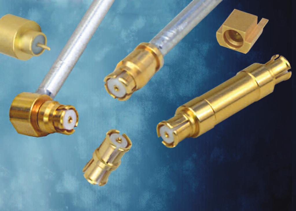
3 Connectivity for SMP Connectors Introduction SMP Blind-Mate Connectors Emerson s new Johnson line of SMP Blind-Mate Connectors offers our customers a Micro-Miniature, Slide-On/Snap-On Interconnect System that aid s in the design ofhigh-density packaging as well as axial and radial misalignment issues. The SMP Interface offers superior performance up to 40 GHz and is compatible with all SMP and GPO Connectors. They offer high electrical reliability where extreme shock and vibration condition s are experienced. Applications (Military and Commercial) Phased Arrays Active Antennas Satellites Communication Airborne Radar Shipborne Radar Equipment Ground Radar Hi-Density Modular Axial/ Radial Packaging Misalignment Solutions Markets Aerospace Broadband Instrumentation Telecom Defense Microwave Transmission Options Box-to-Box Cable-to-Board Board-to-Board Cable-to-Panel-to-Board *GPO is a registered trademark of Corning Gilbert. 3

4 SMP Connectors Introduction Connectivity for Description One of the key benefits of the SMP connector interface is its use in high frequency blind-mate applications. The design of the SMP bullet and shroud system allows for both axial and radial misalignment. The basic system is comprised of an inner bullet adapter, and two outer receptacles called shrouds. The bullet provides a flexible link between the shroud connections. In blind-mate applications, one shroud connector will be typically specified as a snap-on interface and the other as a slide-on. This ensures that the bullet adapter remains fixed in the same shroud connector when the connection is disengaged. The two snap-on interfaces Full Detent (FD) and Limited Detent (LD) each have different engage and disengage coupling forces. The LD is typically selected as the snap-on interface in PCB mount or blind-mate applications, while the FD is mainly used for cabled connections where higher retention forces are required. The two slide-on interfaces Smooth Bore (SM) and Catcher s Mit (CM) allow for reduced connection forces as compared to the snap-on versions. The push-on interface creates a sliding connection that does not physically locate the mating reference planes, allowing for axial and radial misalignment. Both the SM and CM have the same engage/disengage forces; however the CM is typically specified as the shroud configuration in blind-mate applications as its generous lead-in chamfer helps capture and guide the bullet into place. Radial Misalignment Axial Misalignment Bullet Length Shroud 4
5 Connectivity for SMP Connectors Specifications ELECTRICAL SPECIFICATIONS Impedance: 50 Ohms Frequency Range: Bullet Adapter (.254 length), Semi-Rigid Straight Cabled Connectors GHz All other In-Series Adapters, Semi-Rigid Right Angle Cabled Connectors, Field Replaceable Connectors, End Launch Connectors, Hermetic Feedthroughs GHz PC Mount Connectors GHz VSWR: (maximum) 0-18 GHz GHz GHz GHz Bullet Adapter (.254 length) GHz GHz GH Semi-Rigid Straight Cabled Connectors GHz 4-12 GHz GHz All other In-Series Adapters GHz Semi-Rigid Right Angle Cabled Connectors GHz Field Replaceable Connectors (typical, measured back to back with seal pin Un-cabled Connectors (dependant on application) Not Applicable Insertion Loss: (db maximum, tested at 10 GHz) In-Series Adapters, Field Replaceable Connectors F (GHz) Semi-Rigid Cabled Connectors F (GHz) All other Un-cabled Connector Not Applicable Working Voltage: 335 Vrms maximum at sea level, 65 Vrms maximum at 70,000 feet Dielectric Withstanding: Voltage: 500 Vrms minimum at sea level RF High Potential Withstanding Voltage: 325 Vrms minimum at sea level, tested at 4 and 7 MHz Corona Level: 190 Vrms minimum at 70,000 feet Contact Resistance: (milliohms maximum initial, not applicable after environmental testing) Center Contact (Connectors and Adapters) Outer Contact (Connectors and Adapters) Cable Shield to Body (Semi-Rigid Cabled Connectors Only) Insulation Resistance: 5000 megohms minimum RF Leakage: (db typical, tested at 2.5 GHz) Cabled and Field Replaceable Connectors In-Series Adapters All other Un-cabled Connectors Not Applicable 5
6 SMP Connectors Specifications Connectivity for Interface Design: MIL-STD-348A, Series SMP MECHANICAL SPECIFICATIONS Engagement Force: (pounds maximum, mated pair) Full Detent (FD) Limited Detent (LD) Smooth Bore and Catcher s Mit (SM and CM) Disengagement Force: (pounds minimum, mated pair) Full Detent (FD) Limited Detent (LD) Smooth Bore and Catcher s Mit (SM and CM) Mated Radial Misalignment: (inches maximum allowed, female adapters only) Between Centerlines of Mating Planes (FD, LD, SM) Between Centerlines of Mating Planes (CM only) Mated Axial Misalignment:.010 inches maximum allowed between mating planes (female adapters only) Durability: (mating cycles minimum) Full Detent (all female connectors and adapters) Limited Detent (female adapters only) Smooth Bore and Catcher s Mit (female adapters only) Contact Retention: 1.5 pounds minimum axial force (captivated contacts only) Cable Retention: (minimum) Axial Force* (lbs) Torque (in-oz) Cabled Connectors for RG-405 (.086 Semi-Rigid) Cabled Connectors for M17/151 (.047 Semi-Rigid) N/A *Or cable breaking strength, whichever is less Typical Measured Return Loss Bullet Adapter VSWR = 1.10 (0-18 GHz), 1.15 (18-23 GHz), 1.30 ( GHz), 1.70 ( GHz) S11 (db) Frequency (GHz)
7 Connectivity for SMP Connectors Specifications ENVIRONMENTAL SPECIFICATIONS (Meets or Exceeds the Applicable Paragraph of MIL-PRF-39012) Operating Temperature: -65 C to +165 C Thermal Shock: MIL-STD-202, Method 107, Condition B (except high temp +165 C or max high temp of cable) Corrosion: MIL-STD-202, Method 101, Condition B Shock (specified pulse): MIL-STD-202, Method 213, Condition I Vibration: MIL-STD-202, Method 204, Condition D Moisture Resistance: MIL-STD-202, Method 106 (except step 7b omitted) MATERIAL SPECIFICATIONS Spring Finger (female) and End Launch (male) Bodies: Beryllium Copper per ASTM B196, Gold* plated per MIL-DTL ( min) Hermetic Seal Bodies (male): Kovar Alloy per ASTM F15, Gold* plated per MIL-DTL ( min) All other Shroud Bodies (male): Stainless Steel, Type 303, per ASTM A582, Passivated per MIL-DTL (EL 300) Connector and Adapter Contacts (male and female): Beryllium Copper per ASTM B196, Gold* plated per MIL-DTL ( min) Hermetic Seal Center Pins: Kovar Alloy per ASTM F15, Gold* plated per MIL-DTL ( min) EMI/Anti-Rock Rings: Beryllium Copper per ASTM B196, Gold* plated per MIL-DTL ( min) PC Mount Legs: Brass per ASTM B16, Gold* plated per MIL-DTL ( min) Connector and Adapter Insulators: PTFE per ASTM D1710 Hermetic Seal Glass: Corning 7070 *All gold plated parts include a min nickel barrier layer. MOUNTING HOLES Fig 1 Fig 2 Fig 3 This pattern is for reference only. Pattern will vary depending on board type and specific electrical and mechanical requirements. 7
8 SMP Connectors Specifications Connectivity for Mating Engagement for SMP Series per MIL-STD-348A Notes: 1. Socket to accept mating pin Ø.015±.001 (0.38±0.03). 2. EMI/Anti-Rock Ring configuration optional, used on cabled connectors only. Shall not prevent proper mating engagement. 3. All dimensions shown in inches. Metric equivalents (rounded to nearest 0.01mm) are given for general information only. SMP Female Connector Interface Dimension Cabled Uncabled Minimum Maximum Minimum Maximum A.025 (0.64).035 (0.89).018 (0.46).025 (0.64) SMP Male Connector Interface Dimension Full Detent Limited Detent Smooth Bore Catcher s Mit Minimum Maximum Minimum Maximum Minimum Maximum Minimum Maximum B.051 (1.30).057 (1.45).054 (1.37).060 (1.52).059 (1.50).065 (1.65) N/A N/A C.0205 (0.52).0235 (0.60).0205 (0.52).0235 (0.60) N/A N/A N/A N/A D.003 (0.08).008 (0.20).003 (0.08).008 (0.20).003 (0.08).008 (0.20).043 (1.09).047 (1.19) E.033 (0.84).037 (0.94).033 (0.84).037 (0.94).033 (0.84).037 (0.94) N/A N/A F.139 (3.53).145 (3.68).139 (3.53).145 (3.68).139 (3.53).145 (3.68).123 (3.12).127 (3.23) G.114 (2.90).118 (3.00).118 (3.00).122 (3.10).123 (3.12).127 (3.23) N/A N/A H.124 (3.15).126 (3.20).124 (3.15).126 (3.20) N/A N/A N/A N/A K 35 REF 35 REF 35 REF 35 REF 35 REF 35 REF N/A N/A M 30 REF 30 REF 30 REF 30 REF N/A N/A N/A N/A 8

9 Connectivity for SMP Connectors Application Straight Solder Type Cabled Female Cable Type VSWR & Freq. Range* Gold Plated Figure M17/151,.047 Semi-Rigid 1.20 Max 0-18 GHz, Max GHz, 1.70 Max GHz RG-405,.086 Semi-Rigid 1.20 Max 0-18 GHz, Max GHz, 1.70 Max GHz Fig 1 Fig 2 * Specifications dependant on cable ratings Right Angle Solder Type Cabled Female Cable Type VSWR & Freq. Range Gold Plated A B M17/151,.047 Semi-Rigid 1.20 Max 0-18 GHz (6.30).197 (5.00) RG-405,.086 Semi-Rigid 1.20 Max 0-18 GHz (6.88).209 (5.31) Straight PC Mount Male Receptacle Interface Freq. Range Passivated* A Full Detent 0-12 GHz (5.54) Limited Detent 0-12 GHz (5.54) Smooth Bore 0-12 GHz (5.54) Catcher s Mit 0-12 GHz (5.94) * Base and legs Gold plated brass Mounting hole layout figure 3 on page 7. 9
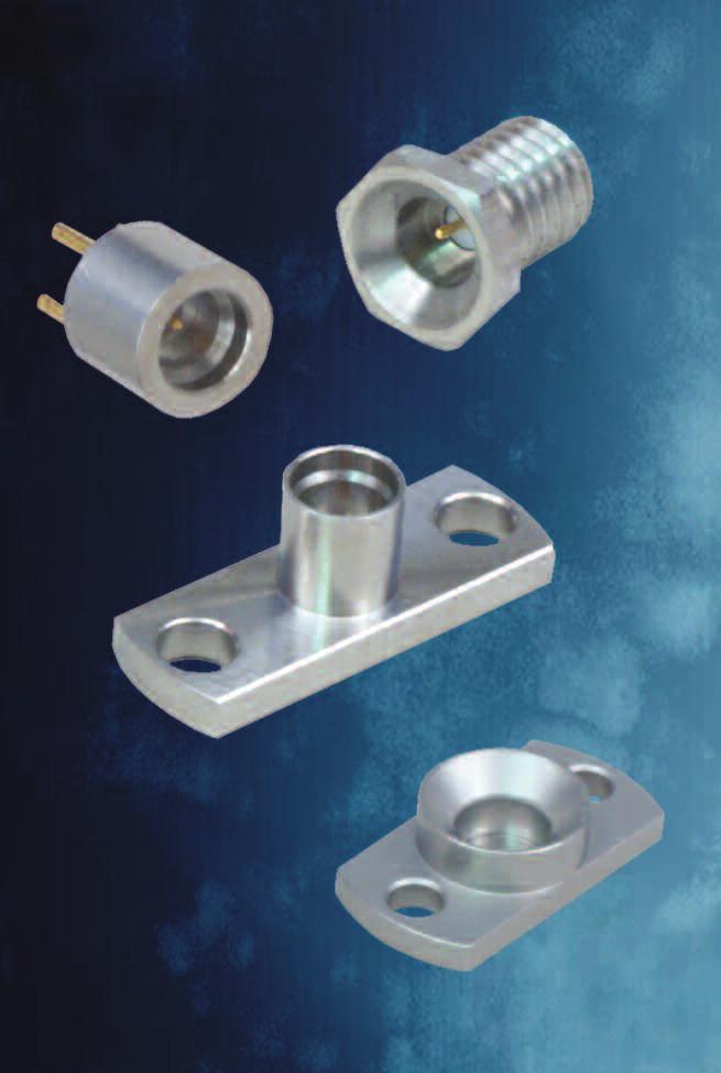
10 SMP Connectors Application Connectivity for End Launch Male Receptacle Surface Mount Interface Freq. Range Gold Plated Packaging Full Detent 0-18 GHz Stock Full Detent 0-18 GHz Tape and Reel pieces Limited Detent 0-18 GHz Stock Limited Detent 0-18 GHz Tape and Reel pieces Smooth Bore 0-18 GHz Stock Smooth Bore 0-18 GHz Tape and Reel pieces Mounting hole layout figure 1 on page 7. 2-Hole Flange Mount Male Shroud - Without Contact Interface Passivated Full Detent Limited Detent Smooth Bore Hole Flange Mount Male Catcher s Mit Shroud - Without Contact Interface Passivated Catcher s Mit
 Limited Detent 1.15 Typical 0-18 GHz 127-1701-612.012 (.030) Smooth Bore 1.15 Typical 0-18 GHz 127-2701-612.012 (.030) * Two connectors mated back to back with hermetic seal fixture Hermetic Seal Male Interface Freq.")
11 Connectivity for SMP Connectors Application 2-Hole Flange Mount Male Field Replaceable Interface VSWR & Freq. Range* Passivated Accepts Pin Size Full Detent 1.15 Typical 0-18 GHz (.030) Limited Detent 1.15 Typical 0-18 GHz (.030) Smooth Bore 1.15 Typical 0-18 GHz (.030) * Two connectors mated back to back with hermetic seal fixture Hermetic Seal Male Interface Freq. Range Gold Plated Full Detent 0-18 GHz Limited Detent 0-18 GHz Smooth Bore 0-18 GHz Mounting hole layout figure 2 on page 7. Female to Female Bullet Adapter VSWR & Freq. Range Gold Plated 1.10 Max 0-18 GHz, Max GHz, 1.30 Max GHz, 1.70 Max GHz 11


12 SMP Connectors Application Connectivity for Female to Female Adapter VSWR & Freq. Range Gold Plated 1.10 Max 0-4 GHz, Max 4-12 GHz, 1.20 Max GHz Male to Male Catcher s Mit Adapter Interface VSWR & Freq. Range Passivated Full Detent 1.10 Max 0-4 GHz, Max 4-12 GHz, 1.20 Max GHz Limited Detent 1.10 Max 0-4 GHz, Max 4-12 GHz, 1.20 Max GHz Smooth Bore 1.10 Max 0-4 GHz, Max 4-12 GHz, 1.20 Max GHz 12


13 Connectivity for SMP Connectors Assembly Tools SMP Customer Tooling Accurate assembly of the Semi-Rigid Cabled Connectors is obtained with the tools listed below. Industry standard devices are used if possible for customer convenience and tool compatibility. E. C. D. G. F. B. H. A. I. J. Item Description Part Number A SMP Bullet Extraction Tool B SMP Cabled Connector Removal Tool C Soldering Vise (does not include clamp inserts or stop screw) D Stop Screw for Soldering Vise E Semi-Rigid Cable Clamp Inserts for.086" OD Cable Semi-Rigid Cable Clamp Inserts for.047" OD Cable F Solder Shim for.086" OD Cable G SMP Center Contact Holder H SMP Interface Locator Tool I SMP Right Angle Body Holder J SMP FD Shroud Centering Tool SMP LD Shroud Centering Tool SMP SB Shroud Centering Tool
14 SMP Connectors Assembly Instructions Connectivity for ASSEMBLY INSTRUCTIONS SMP Straight Female Solder Style for.047 OD Semi-Rigid Cable 1 Identify tools (5 piece parts) and connector parts (3 piece parts). 2. Strip cable jacket and dielectric to dimension shown. Do not nick center conductor. Clean all debris from prepared cable. 3. Insert center conductor into cable stop as shown and place contact onto center conductor. 4. Insert contact into contact holder fixture and clamp cable in vise. Tighten stop screw until light pressure is applied between contact, cable stop and cable jacket. 5. Solder contact to center conductor through solder hole using.016 (0.41) diameter flux core solder wire or solder paste. Use a minimum amount of solder and heat for a good joint. Do not allow heat to build up for a long period of time as cable stop may melt. 6. After solder joint has cooled, remove cable from vise. Remove any excess solder from contact with a sharp blade and clean all debris from contact and cable. 7. Insert contact into connector assembly, making sure cable stop bottoms out against internal shoulder of connector body. Insert connector assembly into interface location fixture and clamp cable in vise. Make sure connector assembly is fully engaged within location fixture. Tighten stop screw until light pressure is applied between connector assembly and cable stop. 8. Solder end of connector body to cable jacket, using a minimum amount of solder and heat for a full fillet joint. Allow assembly to cool before removing connector from vise and location fixture. Best results are obtained when contact location is flush to.004 (0.10) recessed from reference plane. Interface location fixture is pre-set at factory, but can be adjusted to control location. Cable Group Part Number MIL-C-17/151,.047 Semi-Rigid Tool Part Number Cable Vise Stop Screw Clamp Inserts Contact Holder Interface Location Fixture
15 Connectivity for SMP Connectors Assembly Instructions SMP Right Angle Female Solder Style for.047 OD Semi-Rigid Cable 1. Identify tools (5 piece parts) and connector parts (3 piece parts). 2. Strip cable jacket and dielectric to dimension shown. Do not nick center conductor. Clean all debris from prepared cable. 3. Insert center conductor into cable stop as shown. Make sure slot in connector contact is aligned with cross hole in body as shown. Insert cable into cross hole in connector body, making sure cable stop bottoms out against internal shoulder of connector body. 4. Insert connector assembly into interface location fixture and clamp cable in vise using body holder fixture as shown. Tighten stop screw until light pressure is applied between connector body, cable stop and cable jacket. 5. Solder contact to center conductor through rear access port in connector body using a minimum amount of solder and heat for a good joint. 6. After center conductor solder joint has cooled, solder connector body to cable jacket, using a minimum amount of solder and heat for a full fillet joint. Take care so that solder does not flow onto anti-rock ring or into rear access port. Allow assembly to cool before removing connector from vise and location fixture. 7. Using a fixture plate as shown, press end cap into rear access port using a.156 (3.96) diameter flat punch until fully seated within body counter bore. 8. Best results are obtained when contact location is flush to.004 (0.10) recessed from reference plane. Interface location fixture is pre-set at factory, but can be adjusted to control location. Cable Group Part Number MIL-C-17/151,.047 Semi-Rigid Tool Part Number Cable Vise Stop Screw Clamp Inserts Body Holder Interface Location Fixture
16 SMP Connectors Assembly Instructions Connectivity for SMP Straight Female Solder Style for.086 OD Semi-Rigid Cable 1. Identify tools (6 piece parts) and connector parts (2 piece parts). 2. Strip cable jacket and dielectric to dimension shown. Do not nick center conductor. Clean all debris from prepared cable. 3. Place contact onto center conductor, insert solder shim between cable jacket and contact. 4. Insert contact into contact holder fixture and clamp cable in vise. Tighten stop screw until light pressure is applied between contact, solder shim and cable jacket. 5. Solder contact to center conductor through solder hole using.016 (0.41) diameter flux core solder wire or solder paste. Use a minimum amount of solder and heat for a good joint. Do not allow heat to build up for a long period of time as cable dielectric will expand. 6. After solder joint has cooled, remove solder shim and cable from vise. Remove any excess solder from contact with a sharp blade and clean all debris from contact and cable. 7. Insert contact into connector assembly, making sure cable jacket bottoms out against internal shoulder of connector body. Insert connector assembly into interface location fixture and clamp cable in vise. Make sure connector assembly is fully engaged within location fixture. Tighten stop screw until light pressure is applied between connector assembly and cable jacket. 8. Solder end of connector body to cable jacket, using a minimum amount of solder and heat for a full fillet joint. Allow assembly to cool before removing connector from vise and location fixture. Best results are obtained when contact location is flush to.004 (0.10) recessed from reference plane. Interface location fixture is pre-set at factory, but can be adjusted to control location. Cable Group Part Number RG-405,.086 Semi-Rigid Tool Part Number Cable Vise Stop Screw Clamp Inserts Solder Shim Contact Holder Interface Location Fixture
17 Connectivity for SMP Connectors Assembly Instructions SMP Right Angle Female Solder Style for.086 OD Semi-Rigid Cable 1. Identify tools (5 piece parts) and connector parts (2 piece parts). 2. Strip cable jacket and dielectric to dimension shown. Do not nick center conductor. Clean all debris from prepared cable. 3. Make sure slot in connector contact is aligned with cross hole in body as shown. Insert cable into cross hole in connector body, making sure cable jacket bottoms out against internal shoulder of connector body. 4. Insert connector assembly into interface location fixture and clamp cable in vise using body holder fixture as shown. Tighten stop screw until light pressure is applied between connector body and cable jacket. 5. Solder contact to center conductor through rear access port in connector body using a minimum amount of solder and heat for a good joint. Do not allow solder to build up along exposed center conductor. 6. After center conductor solder joint has cooled, solder connector body to cable jacket, using a minimum amount of solder and heat for a full fillet joint. Take care so that solder does not flow onto anti-rock ring or into rear access port. Allow assembly to cool before removing connector from vise and location fixture. 7. Using a fixture plate as shown, press end cap into rear access port using a.156 (3.96) diameter flat punch until fully seated within body counter bore. 8. Best results are obtained when contact location is flush to.004 (0.10) recessed from reference plane. Interface location fixture is pre-set at factory, but can be adjusted to control location. Cable Group Part Number RG-405,.086 Semi-Rigid Tool Part Number Cable Vise Stop Screw Clamp Inserts Body Holder Interface Location Fixture
18 SMP Connectors Assembly Instructions Connectivity for SMP Hermetic Seal Installation 1. Prepare housing panel per figure 2 as shown on page Install solder ring on hermetic seal as shown. Recommended ring size is.103 (2.62) ID x.128 (3.25) OD x.015 (0.38) Thick. 3. Solder in place as shown. Interface Part Number Full Detent Limited Detent Smooth Bore SMP Shroud Installation 1. Install appropriate assembly tool into shroud as shown. 2. While holding tool in place, align flange mount with mounting holes in panel. Install fasteners and torque to 6-8 in/lbs. Shroud Part Number Tool Part Number
19 Connectivity for SMP Connectors Cross Reference COMPETITOR CROSS REFERENCE Description Johnson Tensolite Corning Gilbert Micro-Mode SV Microwave AEP Rosenberger Straight Female M17/151 (.047 SR) Cabled P651-1CC A014-B11-01 MMSP K E4 Straight Female RG 405 (.086 SR) Cabled P651-2CC A014-D11-01 MMSP K E4 Right Angle Female M17/151 (.047 SR) Cabled P652-1CC A015-B11-01 MMSP K E4 Right Angle Female RG 405 (.086 SR) Cabled P652-2CC A015-D11-01 MMSP K E4 Field Replaceable.012 Socket 2 Hole Flange Male FD P836-4CCF SF Field Replaceable.012 Socket 2 Hole Flange Male LD P836-5CCF Field Replaceable.012 Socket 2 Hole Flange Male SB P836-6CCF Adapter Bullet Female/Female P650-1CC A1A MMSP K101-K00E4 Adapter Female/Female P617-1CC MMSP K115-K00E4 Adapter Male CM/Male FD P912-1CCSF A3A Adapter Male CM/Male LD P912-2CCSF Adapter Male CM/Male SB P912-3CCSF SF Shroud 2 Hole Flange.165 Wide x.400 High FD P670-3SF A001-A23-04 MMSP-2514 SF Shroud 2 Hole Flange.165 Wide x.400 High LD P672-3SF A001-A24-04 MMSP-6095 SF Shroud 2 Hole Flange.165 Wide x.400 High SB P673-3SF A001-A25-04 MMSP-6067 SF Shroud 2 Hole Flange.235 Wide x.470 High CM P671-1SF PC Mount Straight.218 OD.100 Legs Male FD P654-5CC A008-L33-01 MMSP-7448 SF PC Mount Straight.218 OD.100 Legs Male LD P654-6CC A008-L34-01 MMSP-7449 PC Mount Straight.218 OD.100 Legs Male SB P654-7CC A008-L35-01 PC Mount Straight.235 OD.100 Legs Male CM P654-8CC End Launch Surface Mount Male FD P606-1CC A010-L13-02 MMSP-7457 End Launch Surface Mount Male LD P606-2CC A010-L14-02 MMSP S202-40ME4 End Launch Surface Mount Male SB P606-3CC A010-L15-02 MMSP-7347 Hermetic Feedthrough Shroud Male FD P840-9CC A007-L MMSP-2771 Hermetic Feedthrough Shroud Male LD P794-2CC A007-L MMSP-2875 Hermetic Feedthrough Shroud Male SB A007-L MMSP
20 Emerson Network Power Connectivity Solutions Johnson 299 Johnson Avenue Waseca, MN USA Tel: Fax: About Emerson Network Power Connectivity Solutions Emerson Network Power Connectivity Solutions, an Emerson business, serves the needs of wireless communications, telephony and data networks, CATV, security systems, health care and industrial facilities with a full spectrum of broadband copper and fiber optic connectivity products. For more information, visit About Emerson Emerson (NYSE: EMR), based in St. Louis, is a global leader in bringing technology and engineering together to provide innovative solutions to customers through its network power, process management, industrial automation, climate technologies, appliance and tools businesses. For more information, visit Emerson Network Power The global leader in enabling business-critical continuity. EmersonNetworkPower. com AC Power Systems Connectivity DC Power Systems Embedded Power Inbound Power Integrated Cabinet Solutions Outside Plant Precision Cooling Site Monitoring and Services Emerson Network Power and the Emerson Network Power logo are trademarks and service marks of Emerson Electric Co Emerson Electric Co SMP11/07 20
Ganged Board to Board SMP Solutions. Catalog. belfuse.com/cinch
 Ganged Board to Board SMP Solutions Catalog belfuse.com/cinch SMP CONNECTORS One of the key benefits of the SMP connector interface is its use in high frequency blind-mate applications. The design of the
Connectors. High Performance to 65 GHz. Applications. PDF Volume 1. Click Here for Table of Contents Click Here for Specifications
 SMP/SMPM Applications DELTA ELECTRONICS MANUFACTURING CORP. Connectors High Performance to 65 GHz PDF Volume 1 Click Here for Table of Contents Click Here for Specifications (978) 927-1060 FAX (978) 922-6430
MCX Connectors. Alphabetical Index. Johnson Components P.O. Box 1732 Waseca, MN Fax:
 MCX Connectors Alphabetical Index 133-3701-201 3 133-3701-206 3 133-3701-211 3 133-3701-216 3 133-3701-221 3 133-3701-226 3 133-3701-231 4 133-3701-236 4 133-3701-301 5 133-3701-306 5 133-3701-311 5 133-3701-316
SMA - 50 Ohm Connectors
 142-0701-621 4 142-0701-626 4 142-0701-631 4 142-0701-636 4 142-0701-701 7 142-0701-706 7 142-1701-011 5 142-1701-016 5 142-1701-031 4 142-1701-036 4 142-1701-041 5 142-1701-046 5 142-1701-121 5 142-1701-126
OSMP Microminiature Push-On Coaxial Connectors
 Introduction Features Intermateable with Gilbert GPO Series Enhanced performance features Simplified ssembly etween Series dapters For OSMP etween Series dapters, see Page 438. OSMP microminiature push-on
SMA - 50 Ohm Connectors
 Alphabetical Index 142-0701-201 4 142-0701-206 4 142-0701-231 4 142-0701-235* 4 142-0701-236 4 142-0701-301 5 142-0701-306 5 142-0701-335* 6 142-0701-421 5 142-0701-426 5 142-0701-491 5 142-0701-496 5
2.92mm (SMK) Connectors
 Connectors") 2.92mm (SMK) Connectors Catalog belfuse.com/cinch The Johnson 2.92mm Connector provides an excellent solution for demanding applications requiring high frequency transmission. Although similar to the SMA
2.92mm (SMK) Connectors Catalog belfuse.com/cinch The Johnson 2.92mm Connector provides an excellent solution for demanding applications requiring high frequency transmission. Although similar to the SMA
Applications & Features, Type SSMP When using blind mate connectors in an application, careful consideration has to be given to choosing the right con
 SSMP Push-On Connectors & Adapters THE SSMP (Sub-Sub-Miniature-Push-On) is a 1.7 mm connector, using solid dielectric interface. The connector is 70% of the size of the SMP and therefore allows even higher
SMP. Description. Compatibility. Content. Interface dimensions (mm/inches) SMP female. Interface dimensions conformable to the following standards:
 SMP female. Interface dimensions conformable to the following standards:") Description Compatibility HUBER+SUHNER Astrolab connectors provide a robust, proven and fully compatible plug-in solution for applications up to 40 GHz. HUBER+SUHNER Astrolab connectors have been MIL-SPEC
Description Compatibility HUBER+SUHNER Astrolab connectors provide a robust, proven and fully compatible plug-in solution for applications up to 40 GHz. HUBER+SUHNER Astrolab connectors have been MIL-SPEC
Microwave Gilbert Push-on Interconnects
 Microwave Gilbert Push-on Interconnects Table of Contents Table of Contents Connect to Precision and Performance 4 Custom Designs 5 Corning Optical Communications RF LLC 6 Reference Guide 8 GPO Products
GMS Interconnect Series Product Information
 GMS Interconnect Series Product Information Microwave Products Product Features: Frequency range: DC up to 23 GHz, Force to engage/disengage: 10 ounces min./2.5 pounds max., Male connectors have full self-centering
Series SMPM-T. Description. Compatibility. Content. Interface dimensions (mm/inches) SMPM-T male (pin contact), smooth bore
 SMPM-T male (pin contact), smooth bore") Series Description The is the smallest threaded open source connector on the market. Its unique and innovative combination of a MIL- STD-348 SMPM female interface connector together with a retractable
Series Description The is the smallest threaded open source connector on the market. Its unique and innovative combination of a MIL- STD-348 SMPM female interface connector together with a retractable
SECTION 12 SSMA/SSMB/SSMC R121/R203/R202 SIMPLIFICATION IS OUR INNOVATON. Visit for more information
 SECTION 12 SSMA/SSMB/SSMC R121/R203/R202 SIMPLIFICATION IS OUR INNOVATON Visit www.radiall.com for more information Contents SSMA Introduction... 12-4 Characteristics... 12-4 Plugs... 12-5 Receptacles...
INCHES (MILLIMETERS) CUSTOMER DRAWINGS AVAILABLE ON REQUEST
 CUSTOMER DRAWINGS AVAILABLE ON REQUEST") TNC Connectors Flexible Cable... 3 In-Series Adapters... 4 Specifications... 2 RF Adapter Kit Adapters... 6 N Connectors Panel Mount and In-Series Adapters... 10 Flexible Cable... 8 Specifications... 7
TNC Connectors Flexible Cable... 3 In-Series Adapters... 4 Specifications... 2 RF Adapter Kit Adapters... 6 N Connectors Panel Mount and In-Series Adapters... 10 Flexible Cable... 8 Specifications... 7
SMK Connectors. General Description. Contents (Click on any line to go to the indicated page) Test Data
 Test Data") SMK Connectors General Description These high-performance SMK (2.92 mm) connectors feature maximum VSWR for cable connectors of 1.15:1 from DC to 18 GHz, and 1.3:1 from 18 to 40 GHz. The maximum VSWR for
SMK Connectors General Description These high-performance SMK (2.92 mm) connectors feature maximum VSWR for cable connectors of 1.15:1 from DC to 18 GHz, and 1.3:1 from 18 to 40 GHz. The maximum VSWR for
Cannon 50 Ohm Connectors
 SMB / SMC Cannon's SMB Snap-on and SMC Screw-on subminiature coaxial connectors have been specifically engineered for high performance and high reliability applications in both military and commercial
SMA Series. Specification. Description. Applications Civil & Military Telecommunication Instrumentation SMA SMA. Interface Mating Dimensions
 Series Specification 50 ohm 0-18 GHZ connectors are adaptable to interconnection requirements of both systems and components. S-Conn offers a wide variety of cable connectors, receptacles, feed thrus,
Mating Interfaces 1,63 (.064) 3,45 (.135) Ø3,71 (.146) MAX Ø6,61 (.260) MAX Ø3,71 (.146) MAX
 3,45 (.135) Ø3,71 (.146) MAX Ø6,61 (.260) MAX Ø3,71 (.146) MAX") SMB / SMC Cannon's SMB Snap-on and SMC Screw-on subminiature coaxial connectors have been specifically engineered for high performance and high reliability applications in both military and commercial
SMB / SMC Cannon's SMB Snap-on and SMC Screw-on subminiature coaxial connectors have been specifically engineered for high performance and high reliability applications in both military and commercial
SMA SERIES COAXIAL CONNECTORS
 General Information Features Part Number Index Applications Coupling types and interface mating dimensions Semi-rigid conformable cable connectors Flexible cable connectors Connectors for modules Bulkhead
Series PC 3.5 precision subminiature connectors
 Series PC 3.5 precision subminiature connectors Description Content HUBER+SUHNER PC 3.5 connectors are precision connectors for use in microwave applications up to 26.5 GHz. They are especially suitable
Our Most Important Connection is with You. SECTION 3. Board-to-Board: MMBX / SMP-MAX R223 / R222M
 SECTION 3 Board-to-Board: MMBX / R223 / R222M Contents MMBX Introduction... 3-4 Interface... 3-5 Characteristics... 3-6 Plugs... 3-7 PCB receptacles... 3-7 to 3-8 Adapters... 3-9 Demo board... 3-10 Panel
In-Series and Between-Series Adapters SMA
 Adapters SMA In-Series and Between-Series Adapters SMA If your choice of SMA Adapter is not shown in this section, please refer to the Table below to determine other possible locations. Should you not
SSMP Interconnect Series
 SSMP Interconnect Series INTRODUCTION Carlisle Interconnect Technologies (CarlisleIT) designed the SSMP connector product line to further improve package density of RF/Microwave systems. The SSMP interface
SERIES MCX 50 MICRO MINIATURE CONNECTORS
 SERIES MCX 50 MICRO MINIATURE CONNECTORS DESCRIPTION CONTENT PAGE HUBER+SUHNER MCX micro miniature snap-on connectors offer you an excellent blend of size, weight, durability and performance for applications
SMA Connectors. RF Coax Connectors. Product Facts
 SMA Connectors Product Facts Performance to 12.4 GHz and beyond Available in various base metal options, including stainless steel, brass and zinc diecast Uses industry standard crimp tools and processes
SMP / SMP-COM / SMP-MAX series R222
 3 SMP / SMP-COM / SMP-MAX series R222 SMP-MAX INTRODUCTION BOARD TO BOARD SOLUTIONS The Best Systems Radiall s engineers work with your engineers allowing us to develop the best competitively priced misalignment
SECTION 1 IMP / UMP R107
 1 SECTION 1 / UMP R107 Contents Introduction... 1-4 to 1-6 Characteristics...1-7 Board to board connectors...1-8 Receptacle packaging...1-9 Assembly instructions... 1-9 to 1-10 UMP Characteristics...1-11
VITA 67 Series. Ideal For Blind Mate Applications. Electrical, Mechanical & Environmental Specifications
 VITA 67 Series Delta Electronics Manufacturing Corp. introduces 4 position (VITA 67.1) and 8 position (VITA 67.2) RF connector housings designed for 3U and 6U formats within the OpenVPX architecture. Ideal
The Custom Interconnect Leader
 7-16 Series.354.276.843.811 ELECTRICAL Nominal Impedance: Frequency Range: Voltage Rating: Dielectric Withstanding Voltage: Insulation Resistance: VSWR: Intermodulation: 50 ohms DC to 7 GHz 2,700 volts
PERFORMANCE SPECIFICATION SHEET CONNECTORS, COAXIAL, RADIO FREQUENCY, SERIES C (UNCABLED-RECEPTACLE, FEMALE, JAM NUT MOUNTED, HERMETIC SEAL, CLASS 2)
") INCH-POUND MIL-PRF-39012/14C 10 August 2016 SUPERSEDING MIL-PRF-39012/14B 18 September 1977 PERFORMANCE SPECIFICATION SHEET CONNECTORS, COAXIAL, RADIO FREQUENCY, SERIES C (UNCABLED-RECEPTACLE, FEMALE,
INCH-POUND MIL-PRF-39012/14C 10 August 2016 SUPERSEDING MIL-PRF-39012/14B 18 September 1977 PERFORMANCE SPECIFICATION SHEET CONNECTORS, COAXIAL, RADIO FREQUENCY, SERIES C (UNCABLED-RECEPTACLE, FEMALE,
Corona 70,000 Ft. Permeability Risetime Degradation (Mated Pair) 2.0 max MH z
 2.0 max MH z") NDL Ultraminiature Triaxial Connectors Connector Specifications Interface Dimensions Ø.020 Ø.082 Ø.168 Ø.162 Electrical Specifications Dielectric Center contact to intermediate contact: 1000 Vrms min Withstanding
NDL Ultraminiature Triaxial Connectors Connector Specifications Interface Dimensions Ø.020 Ø.082 Ø.168 Ø.162 Electrical Specifications Dielectric Center contact to intermediate contact: 1000 Vrms min Withstanding
PERFORMANCE SPECIFICATION ADAPTER, CONNECTOR, COAXIAL, RADIO FREQUENCY, (BETWEEN SERIES SMA TO SERIES TNC), CLASS 2, STRAIGHT PLUG
, CLASS 2, STRAIGHT PLUG") INCH POUND MIL-PRF-55339/48B w/amendment 1 15 June 2017 SUPERSEDING MIL-PRF-55339/48B 30 April 2015 PERFORMANCE SPECIFICATION ADAPTER, CONNECTOR, COAXIAL, RADIO FREQUENCY, (BETWEEN SERIES SMA TO SERIES
INCH POUND MIL-PRF-55339/48B w/amendment 1 15 June 2017 SUPERSEDING MIL-PRF-55339/48B 30 April 2015 PERFORMANCE SPECIFICATION ADAPTER, CONNECTOR, COAXIAL, RADIO FREQUENCY, (BETWEEN SERIES SMA TO SERIES
Board Mount Connector Footprint Design Process
 Board Mount Connector Footprint Design Process STEP 1: Connector Selection Series Force to Engage (Max) Max SB LD FD Freq. SMP 2.0 lbs 10 lbs 15 lbs 40 GHz SMPM 3.5 lbs N/A 8.0 lbs 65 GHz SMPS 3.0 lbs
SMA Connectors Series
 SMA Connectors Series Content Page Description.. 2 Interface Dimensions.. 2 Interface Dimensions in mm/inches.. 2 Characteristics. 3 Cable Connectors 4 PCB Connectors 11 Panel Receptacles.. 13 Adapter
SMA Series - Crimp Plug and Jack
 Plug Features: SMA connectors are semi-precision, subminiature devices that provide repeatable electrical performance. These devices offer broadband performance with low reflection. These properties, along
Board-to-Board connections
 Board-to-Board connections MBX/MFBX/MMBX connectors Edition 2014/08 Innovative connections Your partner for system solutions The HUBER+SUHNER Group is a leading global supplier of components and systems
BMA. 1. Applications & Features, Specifications & Interface Dimensions 2. Connectors of Type BMA 3. Adapters to BMA
 CONTENT BMA INTRODUCTION to CONNECTORS & ADAPTERS Page 9 7/16 Page 15 N BMA Page 45 SBX SBY Page 61 Page 85 1. Applications & Features, Specifications & Interface Dimensions 2. Connectors of Type BMA 37
The Custom Interconnect Leader
 SC Series.337.307.040.003.085.194 MIN FLARE TO MEET GAGE TEST.276 MIN.549.781 ELECTRICAL Nominal Impedance: Frequency Range: Voltage Rating: Dielectric Withstanding Voltage: Insulation Resistance: VSWR:
 N Series Connectors Medium sized connector for high-voltage applications Suited for critical applications and environments Performance to 11 GHz (commercial) and 18 GHz (hi frequency) Intermateable with
SECTION 7 SMA/SMA-COM/BMA R125/R124/R128 SIMPLIFICATION IS OUR INNOVATON. Visit for more information
 SECTION 7 /COM/BMA R125/R124/R128 SIMPLIFICATION IS OUR INNOVATON Visit www.radiall.com for more information Contents BMA Introduction... 74 Characteristics... 75 Plugs... 76 Jacks... 77 to 78 Receptacles...78
End Launch Connector Series. Introduction Specifications Model Numbers Installation Procedures... 63
 End Launch Connector Series Index End Launch Connectors (to 50 GHz).... Page Introduction... 60 Specifications... 61 Model Numbers... 62 Installation Procedures... 63 Test Data (Grounded Coplanar)... 64
TNC SERIES Miniature Coaxial Connectors
 SERIES Miniature Coaxial Connectors FEATURES connectors, medium sized coaxial connectors with thread coupling, are designed for applications where extreme vibration is encountered.the increased rigidity
RF & MW Connectors RF & MW Adapters RF Connectivity. RF & MW Connectors
 RF & MW Connectors - 2.4 mm Connectors - 2.92 mm(k) Connectors - Hermetic Seal (0.02 Glass Bead) - SMP Connectors - BMA Connectors - High Performance End Lanch Connectors - High Performance SMA Connectors
Prices, specifications, statement of warranty, and other terms and conditions are subject to change without notice by Lighthorse Technologies, Inc.
 Section Index Connectors Specifications... 93 Flexible Cable... 95 Panel Mount... 99 Bulkhead... 100 PCB Mount... 101 In Series Adaptors... 103 Other Information Assembly Instructions... 176 Cable Assembly...
Dura-ConTM Hermetic Connectors
 Dura-ConTM Hermetic Connectors Standard Connectors With High Performance Hermetic Seals Catalog cinch.com Cinch Dura-Con Hermetic Connectors offers a high performance hermetic seal designed into our standard
Index. End Launch Connector Series. End Launch Connectors (67 GHz)... Page. Installation Procedure End Launch Connector Dimensions...
... Page. Installation Procedure End Launch Connector Dimensions...") Connector Series Index (67 GHz).... Page Specifications... 51 Introduction... 52 Procedure... 53 Connector Dimensions... 54 Connector Numbers... 55 Typical Test Data... 56 50 Specifications Applications
Connector Series Index (67 GHz).... Page Specifications... 51 Introduction... 52 Procedure... 53 Connector Dimensions... 54 Connector Numbers... 55 Typical Test Data... 56 50 Specifications Applications
FISCHER MINIMAX TM SERIES
 TECHNICAL SPECIFICATIONS FISCHER TM SERIES Fischer Connectors SA All rights reserved Web version 1.0-03.2016 Changes without prior notice FISCHER TM SERIES KEY FEATURES The Fischer MiniMax Series increases
BGA Socketing Systems
 DATA BOOK BGA-TECH04 (REV. 3/04) BGA Socketing Systems Search for a footprint or build a part number online at www.bgasockets.com Solutions for Virtually Any BGA Application BGA Socket Adapter System Designed
PERFORMANCE SPECIFICATION SHEET CONNECTORS, PLUG, ELECTRICAL, COAXIAL, RADIO FREQUENCY, (SERIES N (CABLED), PIN CONTACT, CLASS 2)
, PIN CONTACT, CLASS 2)") INCH-POUND MIL-PRF-39012/1J 21 November 2016 SUPERSEDING MIL-PRF-39012/1J 26 February 2016 PERFORMNCE SPECIFICTION SHEET CONNECTORS, PLUG, ELECTRICL, COXIL, RDIO FREQUENCY, (SERIES N (CLED), PIN CONTCT,
INCH-POUND MIL-PRF-39012/1J 21 November 2016 SUPERSEDING MIL-PRF-39012/1J 26 February 2016 PERFORMNCE SPECIFICTION SHEET CONNECTORS, PLUG, ELECTRICL, COXIL, RDIO FREQUENCY, (SERIES N (CLED), PIN CONTCT,
ndl-q & ndl-t SerieS CONNECTORS
 ndl-q & ndl-t SerieS CONNECTORS TRIAXIAL CONNECTORS Interface Dimensions Mechanical & Environmental Specifications (Ø.168) Temperature Rating Corrosion -65 C to + 165 C MIL-STD-202 Method 101, Test Condition
Modular FLATPAQ. provided, and Elcon will provide samples, typically within one week.
 Modular FLATPAQ Modular FLATPAQ connectors provide custom solutions to hot pluggable AC and DC power needs in a board-to-board format. By using off-the-shelf modular components, power and signal modules,
SMP connectors. the easy connection. Products overview. Applications
 Products overview PCB mount SMD mount plug and Centre pin in SMD, BGA or throughhole configurations Surface mount technology plug and Centre pin in SMD, BGA or throughhole configurations Bulkhead mount
N Connectors Specifications Flexible Cable Semi-Rigid Cable Panel Mount Bulkhead In Series Adaptors...
 Section Index Connectors Specifications... 137 Flexible Cable... 139 Semi-Rigid Cable... 145 Panel Mount... 147 Bulkhead... 148 In Series Adaptors... 149 Other Information Assembly Instructions... 176
0.703 dia. [17.86] Cord Connector Contact Arrangements Shown from rear of connector DIMENSIONS ARE FOR REFERENCE ONLY
![0.703 dia. [17.86] Cord Connector Contact Arrangements Shown from rear of connector DIMENSIONS ARE FOR REFERENCE ONLY](/thumbs/83/88977257.jpg "0.703 dia. [17.86] Cord Connector Contact Arrangements Shown from rear of connector DIMENSIONS ARE FOR REFERENCE ONLY") ONLINE CATALOG SWITCHCRAFT, INC. N. Elston Ave. Chicago, IL 00 77 79-700 FAX: 77 79-19 www.switchcraft.com EN MINI WEATHERTIGHT CONNECTOR SERIES EN CORD CONNECTOR 1.8 [9.8] 0. REF 0.70 dia. [17.8] PIN
ONLINE CATALOG SWITCHCRAFT, INC. N. Elston Ave. Chicago, IL 00 77 79-700 FAX: 77 79-19 www.switchcraft.com EN MINI WEATHERTIGHT CONNECTOR SERIES EN CORD CONNECTOR 1.8 [9.8] 0. REF 0.70 dia. [17.8] PIN
triaxial CONtaCts Overview Features
 triaxal CONtaCts triaxial CONtaCts Overview Smiths Connectors concentric twinax/triax contacts provide flexibility in the design of high speed data systems. The contacts, including the unique sizes 10
SMA. Precision 26.5GHz Connectors
 SMA Precision 26.5GHz Connectors SMA Precision Connectors SMA subminiature connectors are 50 ohm precision connectors initially designed for performance through 18GHz, however the standard interface is
Amphenol High Density HDB 3 /HSB 3 Connectors
 Amphenol HDB 3 /HSB 3 Connectors TABLE OF CONTENTS Amphenol HDB 3 and HSB Connectors 3 Table of Contents..............................45 Introduction - Features, Options, Performance...............................
2M Series Selection Table. 2M801, 2M803, 2M804 and 2M805
 M Series Selection Table M0, M0, M0 and M0 SERIES M0 M0 M0 M0 PAGES Page -0 Pages - Pages - Pages -0 TYPE Dual-Start ACME Thread Bayonet Push-Pull Tri-Start ACME Thread DESCRIPTION More rugged keys and
Extensive range of QPL standard and custom audio connectors trusted by our fighting forces for 35 years. MIL-DTL audio connectors
 Extensive range of QPL standard and custom audio connectors trusted by our fighting forces for 35 years MIL-DTL-55116 audio connectors MIL-DTL-55116 solutions Eaton s MIL--DTL--55116 connectors and cable
Elma Bustronic CompactPCI Reference Sheet
 Elma Bustronic CompactPCI Reference Sheet Rev. 4 5.10.10 The cpci reference sheet provides relevant reference material for the CompactPCI product line. The information provided may change at anytime. Elma
AXOMACH E-16. High data rate links for faster data transmission. Microwave coaxial cables. Panel mount connector QUASI-FLEX. Cable mount connector 2
 AXOMACH High data rate links for faster data transmission AXON proposes AXOMACH, a range of high data rate links composed of low loss microwave coaxial cables and different connector types: AXOMACH Micro-D
PC Board Sockets. Specifications SOCKETS. Surface Mount, Single Piece construction. Throughboard, Two Piece construction. Materials.
 Sockets Contents SMT PCB Sockets Sockets For Ø0.5mm Pin Sockets For Ø0.8mm Pin Sockets For Ø1mm Pin Sockets For Ø2mm Pin Test Sockets IC Socket Strip Dual Row IC Socket Surface Mount, Single Piece construction
Commercial MATE-N-LOK Connectors
 MP Commercial MTE-N-LOK Connectors Product Facts Fully polarized nylon housings Easy cavity identification Locking devices are integral part of design. Connector halves will hold together under severe
Product Specification. Mezza-pede SMT Connector Low Profile 1.0mm Pitch
 Mezza-pede SMT Connector Low Profile 1.0mm Pitch Rev. 1 December 7, 2016 1.0 Scope This product specification applies to 1.0mm pitch Mezza-pede SMT Connectors, designed for the mating and unmating of a
RF Connectors Technical Data Sheet. Gold over Nickel Plated Brass Contact. Size 0.5 in [12.7 mm] . Weight lbs [2.27 g].
![RF Connectors Technical Data Sheet. Gold over Nickel Plated Brass Contact. Size 0.5 in [12.7 mm] . Weight lbs [2.27 g].](/thumbs/76/74366494.jpg "RF Connectors Technical Data Sheet. Gold over Nickel Plated Brass Contact. Size 0.5 in [12.7 mm] . Weight lbs [2.27 g].") RP SMA Female Connector Solder Attachment for PE-SR402AL, PE-SR402FL, PE-SR402FLJ, PE- SR402TN, RG402, Gold Plated Brass Body RF Connectors Technical Data Sheet PE44723 Configuration SMA Female Reverse
RP SMA Female Connector Solder Attachment for PE-SR402AL, PE-SR402FL, PE-SR402FLJ, PE- SR402TN, RG402, Gold Plated Brass Body RF Connectors Technical Data Sheet PE44723 Configuration SMA Female Reverse
HD Series. Signal Connector DIN Applicable Markets: Mil-Aero Space Marine
 Signal Connector DIN 41612 HDC and HDD interchangeable with DIN41612 C and D 0.6 mm and 1.0 mm Hypertac contacts, in a two or three row format Up to 192 positions HDT style offers mixed arrangements with
HIGH POWER HOT PLUGGABLE INTERCONNECTION SYSTEM. US Patent # 6,299,492 B1 2. POWER, RIGHT ANGLE EARLY 3. POWER, RIGHT ANGLE EARLY
 HIGH POWER HOT PLUGGABLE INTERCONNECTION SYSTEM US Patent # 6,299,492 B1 The HOTMATE board to board interconnection system provides a unique method of transferring hot pluggable power requirements within
Rigid/Bus Bars. Standard Copper Rigid / Bus. PC Board Stiffeners and Current Carrying Busses. Table of Contents. Benefits
 Rigid/Bus Bars Circuit Components Inc. PC Board Stiffeners and Current Carrying Busses Table of Contents Standard Copper Rigid Bus Benefits...1 Part Specifications..2 Part Drawings.3 Snap-In Board Stiffener
Amphenol. Printed Circuit Board Technology NAFI + UHD CONNECTORS STANDARD. RELIABLE. PROVEN.
 Amphenol Printed Circuit Board Technology NAFI + UHD CONNECTORS STANDARD. RELIABLE. PROVEN. FEATURES & BENEFITS Available in 2 through 4 rows - Offers maximum design flexibility Tested and qualified to
SPECIFICATION AND PERFORMANCE CHARACTERISTICS OF DVI MALE AND FEMALE CONNECTOR SERIES
 SPECIFICATION AND PERFORMANCE CHARACTERISTICS OF DVI MALE AND FEMALE CONNECTOR SERIES CIRCUIT ASSEMBLY CORP. 18 THOMAS STREET, IRVINE, CA 92618-2777 Page No. 1 CONTENTS CLAUSE PAGE 1.0 SCOPE.. 3 2.0 APPLICABLE
DETAIL SPECIFICATION SHEET
 INCH-POUND MIL-DTL-553/3F w/amendment 8 July 7 SUPERSEDING MIL-DTL-553/3F May 6 DETAIL SPECIFICATION SHEET CONNECTORS, PRINTED CIRCUIT SUBASSEMBLY AND ACCESSORIES: PLUG, STRAIGHT-THRU, 3 thru CONTACT POSITIONS,
8D Series MIL-DTL Series III
 Description High contact density Screw coupling Contact protection: 100% Scoop proof Shell size from 9 to 25 Accessories available (protective caps, backshells, etc ) RFI - EMI shielding and shell to shell
11525A 11524A
 8 Typical Configuration 11900A 11901A 11904A 8059A 1250-1159 1250-1748 85058-60007 11900C 11901C 11901D 11904C 11904D 8059C 1250-1462 85058-60009 1190A 1250-166 1250-174 11525A 11524A 11852B 11852B Option
PIN CONTACT MATING FACE
 Differential Twinax Contacts General Description AMPHENOL DIFFERENTIAL TWINAX CONTACTS Offer several advantages for high data transfer rates, low power consumption and excellent EMI compatibility: Two
Amphenol. Printed Circuit Board Technology NAFI + UHD CONNECTORS STANDARD. RELIABLE. PROVEN.
 Amphenol Printed Circuit Board Technology NAFI + UHD CONNECTORS STANDARD. RELIABLE. PROVEN. UHD FEATURES & BENEFITS 0.100 x 0.050 staggered grid - High density optimizes trace routing through the backplane
EN3 SERIES WEATHERTIGHT CONNECTORS NEW PRODUCT BULLETIN 602
 FEATURES & BENEFITS Sealed to IP68 NEMA 250 (6P) Patented grommet & o-ring free design Available in ribbed or winged coupling ring Cable, panel & cable to cable options Gold plated contacts standard Solder,
AMPMODU* MOD I Interconnection System
 Product Specification AMPMODU* MOD I Interconnection System 03 JUN 2013 Rev E All Paragraphs Revised 1. SCOPE This specification covers performance and test requirements for the AMPMODU MOD I Interconnection
CompactPCI PowerConnector
 CompactPCI PowerConnector Table of Contents 1 Introduction............................................................. 2 Product Features......................................................... 3 Performance
Product Performance Specification Mini Coaxial Connector
 Product Performance Specification Mini Coaxial Connector 1. Scope 1.1 Content This specification covers the performance, tests and quality requirements for the Mini Coaxial connector and connector system.
ATP SERIES ATP Series
 ATP SERIES ATP Series 87 ATP Series Overview ATP Series connectors are designed as a high-performance, cost-effective, thermoplastic solution to be used within the Marine, Heavy Equipment, Agricultural,
Operating voltages up to 40 kvdc Operating current up to 30 Amps Advanced contact technology Silver plated and gold plated contacts available High
 Operating voltages up to 40 kvdc Operating current up to 30 Amps Advanced contact technology Silver plated and contacts available High performance insulation material General characteristics and technical
PERFORMANCE SPECIFICATION
 INCH-POUND MIL-PRF-6106/13F 17 November 2011 SUPERSEDING MIL-PRF-6106/13E 10 November 2000 PERFORMANCE SPECIFICATION RELAY, ELECTROMAGNETIC, 25 AMPERE, 3PST, NO, WITH 2 AMPERE 1PDT AUXILIARY CONTACTS,
IDC for 50mil(1.27mm) Falt Cable with One-touch Locking Ejector System 50mil(1.27mm) PITCH 2 PIECE CONNECTOR 8822E SERIES C-41
 Falt Cable with One-touch Locking Ejector System 50mil(1.27mm) PITCH 2 PIECE CONNECTOR 8822E SERIES C-41") IDC for mil(1.27mm) Falt Cable with One-touch Locking Ejector System mil(1.27mm) PITCH 2 PIECE CONNECTOR 8822E SERIES C-41 8822E/8830E/8831E SERIES 1.27mm PITCH 2 PIECE CONNECTOR / IDC FOR 1.27mm (mil)
IDC for mil(1.27mm) Falt Cable with One-touch Locking Ejector System mil(1.27mm) PITCH 2 PIECE CONNECTOR 8822E SERIES C-41 8822E/8830E/8831E SERIES 1.27mm PITCH 2 PIECE CONNECTOR / IDC FOR 1.27mm (mil)
TXC ULTRA-MINIATURE COAXIAL CONNECTORS. Ultra-Miniature Coaxial Connectors. Features. Materials/Finish. Specifications
 ULTRA-MINIATURE COAXIAL CONNECTORS TXC Ultra-Miniature Coaxial Connectors Features 1: Ultraminiaturization provided by using hermetic beads. 2: The low profile and narrow flange leads to high density mounting.
DEUTSCH AFD Series Connectors Qualified to MIL-DTL Series II
 DEUTSCH AFD Series Connectors Qualified to MIL-DTL-26482 Series II Miniature Circular Connectors with Quick- Connect Bayonet Coupling and Environmental Sealing to Help Withstand Harsh Environments DEUTSCH
PGA / BGA / PLCC SOCKETS
 PGA / BGA / PLCC SOCKETS QUICK SELECTOR CHART PGA / BGA / PLCC PGA BGA PLCC GRID 2.54 mm INTERSTITIAL 1.27 mm 1.27 mm 1 mm SOCKETS Solder tail 156 161 165 SEE PAGE 173 Surface mount 156 161 165 166 169
Introduction. Quadrax Contacts, Connectors and Cables. Product Facts
 Introduction Product Facts n 2 mm centerlines n Designed per ARINC 600 Supplement 18 n Fits into keyed connector inserts for connectors such as: ARINC 404 & 600, General Purpose Rectangular (GPR), MIL-DTL-38999
REFERENCE PLANE Referenzebene
 1Series RPC- 2.92 Interface Dimensions Series RPC-2.92 (code 02) D REFERENCE PLANE Referenzebene REFERENCE PLANE Referenzebene D A E B C F F C B E A MALE Stecker FEMALE Kuppler Series RPC-2.92 Male Stecker
Labs. Introduction. Application Notes
 Introduction Application Notes Florida RF has provided an extensive collection of Application Notes in this section to help designers select and specify cable assemblies. These Application Notes cover
SPRING - LOADED CONNECTORS
 SPRING - LOADED CONNECTORS SPRING LOADED CONNECTORS QUICK SELECTOR CHART SPRING-LOADED CONNECTORS AND PAD CONNECTORS GRID 1.25 mm 2.54 mm SINGLE ROW SINGLE ROW DOUBLE ROW SLC CONNECTORS SEE PAGE Straight
62GB. Amphenol Series 62GB. Applications. Features
 Applications Features 62GB Amphenol 62GB Series connectors are built to British Standard Specification BS 9522 F00 17 which is similar to US military specification MIL-DTL-26482. They are machined from
Quadrax Contacts, Connectors and Cables
 Quadrax Contacts, Connectors and Cables Introduction 2 mm centerlines Designed per ARINC 600 - Supplement 14 Fits into keyed connector inserts for connectors such as: ARINC 404 & 600, General Purpose Rectangular
(MR) Miniature Rectangular Connectors (Continued)
 Miniature Rectangular Connectors (Continued)") Product Facts Housings positively lock to help prevent accidental disengagement Either cap or plug housing can be mounted in same rectangular panel cutout without additional hardware UL94V-0 housings Plug
Product Facts Housings positively lock to help prevent accidental disengagement Either cap or plug housing can be mounted in same rectangular panel cutout without additional hardware UL94V-0 housings Plug
 Distributed by: www.jameco.com 1-800-831-4242 The content and copyrights of the attached material are the property of its owner. 0.80mm (.031") Pitch Small Form-Factor Pluggable (SFP) Receptacle 74441
Series 3402 lightning EMP protectors Gas discharge tube (GDT) technology up to 2.5 GHz
 technology up to 2.5 GHz") lightning EMP protectors Gas discharge tube (GDT) technology up to 2.5 GHz Description HUBER+SUHNER gas discharge tube protectors make the best of the traditional spark gap protection principle for general
lightning EMP protectors Gas discharge tube (GDT) technology up to 2.5 GHz Description HUBER+SUHNER gas discharge tube protectors make the best of the traditional spark gap protection principle for general
DETAIL SPECIFICATION SHEET
 INCH-POUND MIL-DTL-55302/65H 3 February 2004 SUPERSEDING MIL-C-55302/65G 8 April 1993 DETAIL SPECIFICATION SHEET CONNECTORS, PRINTED CIRCUIT SUBASSEMBLY AND ACCESSORIES: RECEPTACLE, SOCKET CONTACTS, DECADE
Elcon CROWN EDGE Card Edge-style High Current Connectors
 Elcon CROWN EDGE Card Edge-style High Current Connectors CROWN EDGE is a board-to-board power interconnect solution that uses Elcon high performance Crown contact technology configured to mate directly
Introduction to High Current Card Edge Connectors
 Introduction to High Current Card Edge Connectors Product Facts Contacts on.100 [2.54] Centerlines Selective gold plating of contacts for high performance at low cost Flow solder applications Glass-filled
PRODUCT SPECIFCATION GS MINI-SAS HD External Cable to Board Connector System. 1 of 14 F. Roger Cheng TYPE NUMBER
 1 of 14 F TABLE OF CONTENTS 1.0 OBJECTIVE... 3 2.0 SCOPE... 3 3.0 APPLICABLE DOCUMENTS... 3 3.1 FCI SPECIFICATIONS... 3 3.2 OTHER STANDARDS AND SPECIFICATIONS... 3 3.3 FCI PRODUCT QUALIFICATION TEST REPORTS...
Front Load Single Sensor
 INFICON Front Load Single crystal sensors offer proven reliability and durability and have the best thermal stability of any sensor head on the market. The front load design allows for easy insertion of