To Interface The 8085 Microprocessor
|
|
|
- Clyde Webster
- 5 years ago
- Views:
Transcription
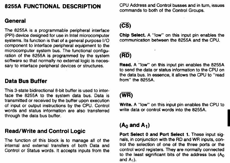
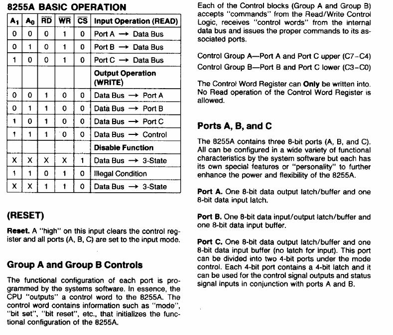
1 To Interface The 8085 Microprocessor A microprocessor has to be interfaced with various peripherals to perform various functions. Let's discuss about the Interfacing techniques in detail. Introduction We know that a microprocessor is the CPU of a computer. A microprocessor can perform some operation on a data and give the output. But to perform the operation we need an input to enter the data and an output to display the results of the operation. So we are using a keyboard and monitor as Input and output along with the processor. Microprocessors engineering involves a lot of other concepts and we also interface memory elements like ROM, EPROM to access the memory. Interfacing Types There are two types of interfacing in context of the 8085 processor. Memory Interfacing. I/O Interfacing. Memory Interfacing: While executing an instruction, there is a necessity for the microprocessor to access memory frequently for reading various instruction codes and data stored in the memory. The interfacing circuit aids in accessing the memory. Memory requires some signals to read from and write to registers. Similarly the microprocessor transmits some signals for reading or writing a data. But what is the purpose of interfacing circuit here? The interfacing process involves matching the memory requirements with the microprocessor signals. The interfacing circuit therefore should be designed in such a way that it matches the memory signal requirements with the signals of the microprocessor. For example for carrying out a READ process, the microprocessor should initiate a read signal which the memory requires to read a data. In simple words, the primary function of a memory interfacing circuit is to aid the microprocessor in reading and writing a data to the given register of a memory chip. I/O Interfacing: We know that keyboard and Displays are used as communication channel with outside world. So it is necessary that we interface keyboard and displays with the

2 microprocessor. This is called I/O interfacing. In this type of interfacing we use latches and buffers for interfacing the keyboards and displays with the microprocessor. But the main disadvantage with this interfacing is that the microprocessor can perform only one function. It functions as an input device if it is connected to buffer and as an output device if it is connected to latch. Thus the capability is very limited in this type of interfacing. Programmable Peripheral Devices Programmable peripheral devices were introduced by Intel to increase the overall performance of the system. These devices along with I/O functions, they perform various other functions such as time delays, counters and interrupt handling. These devices are nothing but a combination of many devices on a single chip. A programmable device can be set up to perform specific function by writing a code in the internal register. As this code controls the function of the device it s called control word and internal register in which it is stored is called Control Register. INTEL developed some peripheral devices for processors like 8085/8086/8088. The peripheral devices includes 8255 Parallel Communication Interface (PPI) 8251 Serial communication Interface (USART- Universal Synchronous/Asynchronous Receiver/Transmitter) 8257 DMA Controller 8279 Keyboard/Display Controller Programmable Interrupt controller 8254 Programmable Timer
3 Types of Communication Interface There are two ways in which a microprocessor can connect with outside world or other memory systems. Serial Communication Interface Parallel Communication interface Serial Communication Interface: In serial communication interface, the interface gets a single byte of data from the microprocessor and sends it bit by bit to other system serially (or) the interface receives data bit by bit serially from the external systems and converts the data into a single byte and transfers it to the microprocessor. Parallel Communication Interface: This interface gets a byte of data from microprocessor and sends it bit by bit to the other systems in simultaneous (or) parallel fashion. The interface also receives data bit by bit simultaneously from the external system and converts the data into a single byte and transfers it to microprocessor. Consider that we have a microprocessor interfaced to both I/O device and also a memory chip. Now how to select between the two devices according to the requirement? For this purpose an address decoding circuit is used. An address decoding circuit aids in selecting the required I/O device or a memory chip. 1.THE 8255 PROGRAMMABLE PERIPHERAL INTERFACE (PPI) IS A WIDELY USED, PROGRAMMABLE, PARALLEL I/O DEVICE. It can be programmed to transfer data under various conditions from simple I/O to interrupt I/O. It is flexible, versatile & economical (when multiple I/O ports are required), but somewhat complex. It is an important general purpose I/O device that can be used with almost any P. BLOCK DIAGRAM & PIN CONFIGRATION OF 8255.
4
5
6
7
8
9 8255 Control Word format in the BSR Mode
10
11
12
13
14
15
16
17
18
19
20 Pinout
21
22
23
24
25
26
27

28
29
30
31
32
33
34
35 8254 PROGRAMMABLE INTERVAL TIMER Features Status read-back command Counter latch command Read/write least significant bit (LSB) only, most significant bit (MSB) only,or LSB first then MSB Six programmable counter modes o Interrupt on terminal count o Hardware retriggerable one-shot o Rate generator o Square wave mode
36 o Software-triggered strobe o Hardware-triggered strobe (retriggerable) Binary or binary coded decimal strobe Developed in VHDL and synthesizes to approximately 5,000 gates Functionally based on the Intel 82C54 device
37 Description The 8254 programmable interval time/counter megafunction is a highperformance function that is designed to solve the common timing control problems in microcomputer system design. It provides three independent 16-bit counters, and each counter may operate in a different mode. All modes are software programmable. The 8254 megafunction solves one of the most common problems in any microcomputer system: the generation of accurate time delays under software control. Instead of setting up timing loops in software, the 8254 megafunction can be
38 programmed to match requirements by programming one of the counters for the desired delay. OPERATIONAL DESCRIPTION General After power-up, the state of the 8254 is undefined.the Mode, count value, and output of all Counters are undefined.how each Counter operates is determined when it is programmed. Each Counter must be programmed before it can be used. Unused counters need not be programmed. By contrast, initial counts are written into the Counters,not the Control Word Register. The A1,A0 inputs are used to select the Counter to be written into. The format of the initial count is determined by the Control Word used. Write Operations The programming procedure for the 8254 is very flexible. Only two conventions need to be remembered: 1) For each Counter, the Control Word must be written before the initial count is written. 2) The initial count must follow the count format specified in the Control Word (least significant byte only, most significant byte only, or least significant byte and then most significant byte). Since the Control Word Register and the three Counters have separate addresses (selected by the A1,A0 inputs), and each Control Word specifies the Counter it applies to (SC0,SC1 bits), no special instruction sequence is required. Any programming sequence that follows the conventions in Figure 7 is acceptable. A new initial count may be written to a Counter at any time without affecting the Counter's programmed Mode in any way. Counting will be affected as described in the Mode definitions. The new count must follow the programmed count format.if a Counter is programmed to read/write two-byte counts, the following precaution applies: A program must not transfer control between writing the first and second byte to another routine which also writes into that same Counter. Otherwise, the Counter will be loaded with an incorrect count. Read Operations
39 It is often desirable to read the value of a Counter without disturbing the count in progress. This is easily done in the 8254 There are three possible methods for reading the counters: a simple read operation, the Counter Latch Command, and the Read-Back Command.Each is explained below. The first method is to perform a simple read operation. To read the Counter,which is selected with the A1, A0 inputs, the CLK input of the selected Counter must be inhibited by using either the GATE input or external logic. Otherwise, the count may be in the process of changing when it is read, giving an undefined result. Mode Definitions The following are defined for use in describing the operation of the CLK Pulse: a rising edge, then a falling edge, in that order, of a Counter's CLK input.trigger: a rising edge of a Counter's GATE input. Counter loading: the transfer of a count from the CR to the CE (refer to the ``Functional Description'') MODE 0: INTERRUPT ON TERMINAL COUNT Mode 0 is typically used for event counting. After the Control Word is written, OUT is initially low, and will remain low until the Counter reaches zero. OUT then goes high and remains high until a new count or a new Mode 0 Control Word is written into the Counter. GATE = 1 enables counting; GATE = 0 disables counting. GATE has no effect on OUT. After the Control Word and initial count are written to a Counter, the initial count will be loaded on the next CLK pulse. This CLK pulse does not decrement the count, so for an initial count of N, OUT does not go high until N a 1 CLK pulses after the initial count is written. If a new count is written to the Counter, it will be loaded on the next CLK pulse and counting will continue from the new count. If a two-byte count is written,the following happens: 1) Writing the first byte disables counting. OUT is set low immediately (no clock pulse required) 2) Writing the second byte allows the new count to be loaded on the next CLK pulse. This allows the counting sequence to be synchronized by software. Again, OUT does not go high until Na1 CLK pulses after the new count of N is written. If an initial count is written while GATE e 0, it will still be loaded on the next CLK pulse. When GATE goes high, OUT will go high N CLK pulses later; no CLK pulse is needed to load the Counter as this has already been done.

40 MODE 1: HARDWARE RETRIGGERABLE ONE-SHOT OUT will be initially high. OUT will go low on the CLK pulse following a trigger to begin the one-shot pulse,and will remain low until the Counter reaches zero. OUT will then go high and remain high until the CLK pulse after the next trigger.
41 After writing the Control Word and initial count, the Counter is armed. A trigger results in loading the Counter and setting OUT low on the next CLK pulse,thus starting the one-shot pulse. An initial count of N will result in a one-shot pulse N CLK cycles in duration. The one-shot is retriggerable, hence OUT will remain low for N CLK pulses after any trigger. The one-shot pulse can be repeated without rewriting the same count into the counter. GATE has no effect on OUT If a new count is written to the Counter during a oneshot pulse, the current one-shot is not affected unless the counter is retriggered. In that case, the Counter is loaded with the new count and the oneshot pulse continues until the new count expires. MODE 2: RATE GENERATOR This Mode functions like a divide-by-n counter. It is typically used to generate a Real Time Clock interrupt.out will initially be high. When the initial count has decremented to 1, OUT goes low for one CLK pulse. OUT then goes high again, the Counter reloads the initial count and the process is repeated.mode 2 is periodic; the same sequence is repeated indefinitely. For an initial count of N, the sequence repeats every N CLK cycles.
42 GATE = 1 enables counting; GATE = 0 disables counting. If GATE goes low during an output pulse,out is set high immediately. A trigger reloads the Counter with the initial count on the next CLK pulse;out goes low N CLK pulses after the trigger. Thus the GATE input can be used to synchronize the Counter. After writing a Control Word and initial count, the Counter will be loaded on the next CLK pulse. OUT goes low N CLK Pulses after the initial count is written. This allows the Counter to be synchronized by software also. Writing a new count while counting does not affect the current counting sequence. If a trigger is received after writing a new count but before the end of the current period, the Counter will be loaded with the new count on the next CLK pulse and counting will continue from the new count. Otherwise, the new count will be loaded at the end of the current counting cycle. In mode 2, a COUNT of 1 is illegal. MODE 3: SQUARE WAVE MODE
43 Mode 3 is typically used for Baud rate generation.mode 3 is similar to Mode 2 except for the duty cycle of OUT. OUT will initially be high. When half the initial count has expired, OUT goes low for the remainder of the count. Mode 3 is periodic; the sequence above is repeated indefinitely. An initial count of N results in a square wave with a period of N CLK cycles. GATE e 1 enables counting; GATE e 0 disables counting. If GATE goes low while OUT is low, OUT is set high immediately; no CLK pulse is required. A trigger reloads the Counter with the initial count on the next CLK pulse. Thus the GATE input can be used to synchronize the Counter. After writing a Control Word and initial count, the Counter will be loaded on the next CLK pulse. This allows the Counter to be synchronized by software also. Writing a new count while counting does not affect the current counting sequence. If a trigger is received after writing a new count but before the end of the current half-cycle of the square wave, the Counter will be loaded with the new count on the next CLK pulse and counting will continue from the new count. Otherwise, the new count will be loaded at the end of the current half-cycle. Mode 3 is implemented as follows: Even counts: OUT is initially high. The initial count is loaded on one CLK pulse and then is decremented by two on succeeding CLK pulses. When the count expires OUT changes value and the Counter is reloaded with the initial count. The above process is repeated indefinitely. Odd counts: OUT is initially high. The initial count minus one (an even number) is loaded on one CLK pulse and then is decremented by two on succeeding CLK pulses. One CLK pulse after the count expires,out goes low and the Counter is reloaded with the initial count minus one. Succeeding CLK pulses decrement the count by two. When the count expires, OUT goes high again and the Counter is reloaded with the initial count minus one. The above process is repeated indefinitely. So for odd counts, OUT will be high for (N a 1)/2 counts and low for (N b 1)/2 counts
44 MODE 4: SOFTWARE TRIGGERED STROBE OUT will be initially high. When the initial count expires,out will go low for one CLK pulse and then go high again. The counting sequence is ``triggered'' by writing the initial count. GATE = 1 enables counting; GATE = 0 disables counting. GATE has no effect on OUT After writing a Control Word and initial count, the Counter will be loaded on the next CLK pulse. This CLK pulse does not decrement the count, so for an initial count of N, OUT does not strobe low until N a 1 CLK pulses after the initial count is written. If a new count is written during counting, it will be loaded on the next CLK pulse and counting will continue from the new count. If a two-byte count is written,the following happens: 1) Writing the first byte has no effect on counting. 2) Writing the second byte allows the new count to be loaded on the next CLK pulse. This allows the sequence to be ``retriggered'' by software. OUT strobes low N a 1 CLK pulses after the new count of N is written.
45 MODE 5: HARDWARE TRIGGERED STROBE (RETRIGGERABLE)
46 OUT will initially be high. Counting is triggered by a rising edge of GATE. When the initial count has expired, OUT will go low for one CLK pulse and then go high again. After writing the Control Word and initial count, the counter will not be loaded until the CLK pulse after a trigger. This CLK pulse does not decrement the count, so for an initial count of N, OUT does not strobe low until N a 1 CLK pulses after a trigger. A trigger results in the Counter being loaded with the initial count on the next CLK pulse. The counting sequence is retriggerable. OUT will not strobe low for N a 1 CLK pulses after any trigger. GATE has no effect on OUT. If a new count is written during counting, the current counting sequence will not be affected. If a trigger occurs after the new count is written but before the current count expires, the Counter will be loaded with the new count on the next CLK pulse and counting will continue from there
47 APPLICATIONS Unipolar full step Stepper motor: INPUT SEQUENCE: X Y X Y CONTROL WORD: =80H PROGRAM: MVI A, 80 OUT port B START MVI A, FC OUT port A CALL DELAY MVI A, F6 OUT port A CALL DELAY MVI A, F3 OUT port A CALL DELAY MVI A, F9 OUT port A JMP START DELAY LXI D, 0003 CALL DELAY RET
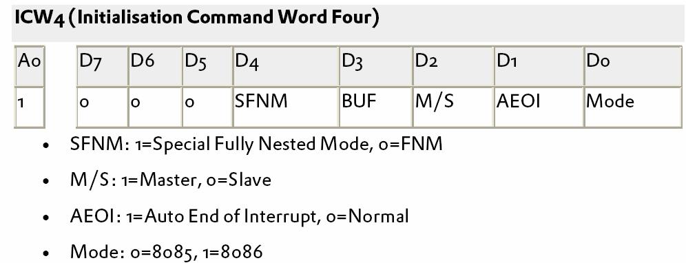
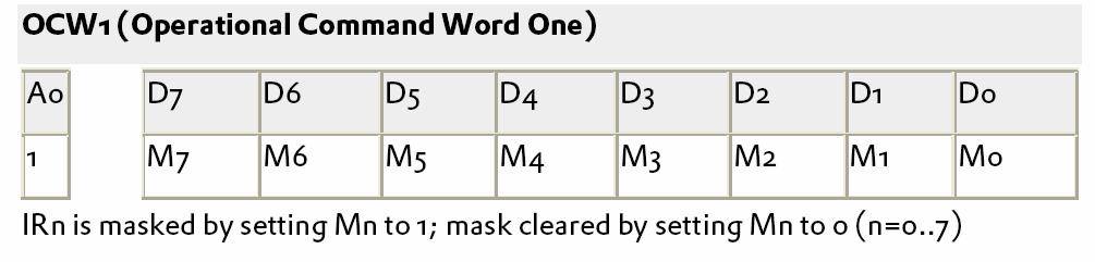
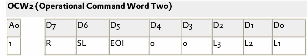
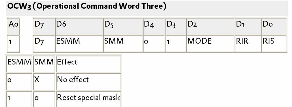
48 MULTIPLE CHOICE: 1. If an information flows from memory to microprocessor, which signal is used by it 2. is used to enable the memory chip 3.If the starting address of 6K memory is 0D00, then ending address will be 4.. If an information flows to memory, which signal is used by it 5. The assignment of addresses to various I/O devices in a memory chip is called 6. is used to demultiplex address and data bus. 7. applications of stepper motor 8. is the maximum possible memory size which can be used in a microprocessor QUESTIONS 1. Name the two modes of operation of DMA controller? 2. List the operating modes of 8253 timer. 3. Give the control word format of timer? 4. What is the use of USART? 5. Compare serial and parallel communication. 6. What is the use of Keyboard and display controller? 7. What are the functions performed by 8279? 8. What is PPI? 9. Give the control word format for I/O mode of 8255? 10. Give the BSR mode format of What is the need for interrupt controller? 12. What are the registers present in 8259? 13. What are the applications of 8253? 14. Define interrupts. 15. Define DMA process. 16. Give the status word format of Draw the Block diagram and explain the operations of 8251 serial communication interface. 18. Draw the Block diagram of 8279 and explain the functions of each block. 19. Draw the block diagram of programmable interrupt controller and explain its operations. 20. Discuss in detail about the operation of timer along with its various modes. 21. Draw the Block diagram of DMA controller and explain its operations. 22.What does the CPU do when it receive an interrupt? How do you enable and disable interrupts in 8086.
49 23 Explain the command words/control words of 8259 in details. 24. With the help of block diagram explain various modes of operation of 8259 in details. 25. Explain type 0,1,2 interrupts found interrupt vector table of 8086/8088 microprocessor. 26. Describe the use of CAS0, CAS and CAS2 lines in a system with a cascaded 8259 s. 27. What are the different modes of operation of the 8253 programmable timer? How does 8254 differ from 8253? 28. Which mode will you use to generate a square wave? Give a flow chart to generate it on Explain with neat waveform the mode 0 of the 8253 timer/counter. 30. Explain with the help of block diagram, functioning of 8253 in various programmable modes. 31. A 32-bit binary counter is to be implemented using timer/counter i)design and explain the control word to meet above requirement ii)draw timing diagram of the mod(s) used.
8254 is a programmable interval timer. Which is widely used in clock driven digital circuits. with out timer there will not be proper synchronization
 8254 is a programmable interval timer. Which is widely used in clock driven digital circuits. with out timer there will not be proper synchronization between two devices. So it is very useful chip. The
82C54 CHMOS PROGRAMMABLE INTERVAL TIMER
 CHMOS PROGRAMMABLE INTERVAL TIMER Compatible with all Intel and most other microprocessors High Speed Zero Wait State Operation with 8 MHz 8086 88 and 80186 188 Handles Inputs from DC 10 MHz for -2 Available
General Purpose Programmable Peripheral Devices. Assistant Professor, EC Dept., Sankalchand Patel College of Engg.,Visnagar
 Chapter 15 General Purpose Programmable Peripheral Devices by Rahul Patel, Assistant Professor, EC Dept., Sankalchand Patel College of Engg.,Visnagar Microprocessor & Interfacing (140701) Rahul Patel 1
UNIT - II PERIPHERAL INTERFACING WITH 8085
 UNIT - II PERIPHERAL INTERFACING WITH 8085 Peripheral Interfacing is considered to be a main part of Microprocessor, as it is the only way to interact with the external world. The interfacing happens with
Topics. Interfacing chips
 8086 Interfacing ICs 2 Topics Interfacing chips Programmable Communication Interface PCI (8251) Programmable Interval Timer (8253) Programmable Peripheral Interfacing - PPI (8255) Programmable DMA controller
These three counters can be programmed for either binary or BCD count.
 S5 KTU 1 PROGRAMMABLE TIMER 8254/8253 The Intel 8253 and 8254 are Programmable Interval Timers (PTIs) designed for microprocessors to perform timing and counting functions using three 16-bit registers.
Lecture-55 System Interface:
 Lecture-55 System Interface: To interface 8253 with 8085A processor, CS signal is to be generated. Whenever CS =0, chip is selected and depending upon A 1 and A 0 one of the internal registers is selected
 8254 PROGRAMMABLE INTERVAL TIMER Y Y Y Compatible with All Intel and Most Other Microprocessors Handles Inputs from DC to 10 MHz 8 MHz 8254 10 MHz 8254-2 Status Read-Back Command Y Y Y Y Y Six Programmable
INTERFACING INTERFACING. Richa Upadhyay Prabhu. NMIMS s MPSTME February 25, 2016
 INTERFACING Richa Upadhyay Prabhu NMIMS s MPSTME richa.upadhyay@nmims.edu February 25, 2016 8255: Programmable Peripheral Interface or Programmable Input output Device Introduction METHODS OF DATA TRANSFER
PCI bit Digital Input/ Output Card for PCI Bus. User s Manual
 PCI-1751 48-bit Digital Input/ Output Card for PCI Bus User s Manual Copyright This documentation and the software included with this product are copyrighted 1998 by Advantech Co., Ltd. All rights are
Registers Format. 4.1 I/O Port Address
 4 Registers Format The detailed descriptions of the register format and structure of the ACL- 8112 are specified in this chapter. This information is quite useful for the programmer who wish to handle
PCI-1751U. 48-bit Digital Input/Output Card with Universal PCI Bus. User Manual
 PCI-1751U 48-bit Digital Input/Output Card with Universal PCI Bus User Manual Copyright This documentation and the software included with this product are copyrighted 2006 by Advantech Co., Ltd. All rights
The 8255A: Programmable Peripheral Interface
 CMP:885 Peripherals Summary- EE39: Computer Organization, rchitecture and MicroProcessors http://www.ee.iitb.ac.in/ sumantra/courses/up/up.html The 855: Programmable Peripheral Interface PROGRMMER S VIEW
PERIPHERAL INTERFACING Rev. 1.0
 This work is licensed under the Creative Commons Attribution-NonCommercial-Share Alike 2.5 India License. To view a copy of this license, visit http://creativecommons.org/licenses/by-nc-sa/2.5/in/deed.en
PART B UNIT II PART A
 SRM INSTITUTE OF SCIENCE AND TECHNOLOGY (Deemed University) DEPARTMENT OF COMPUTER SCIENCE AND ENGINEERING QUESTION BANK SUB : Microprocessor/CS201 YEAR/SEM : II/III UNIT I PART - A 1. Differentiate accumulator
Interface DAC to a PC. Control Word of MC1480 DAC (or DAC 808) 8255 Design Example. Engineering 4862 Microprocessors
 8255 Design Example. Engineering 4862 Microprocessors") Interface DAC to a PC Engineering 4862 Microprocessors Lecture 22 Cheng Li EN-4012 licheng@engr.mun.ca DAC (Digital-to-Analog Converter) Device used to convert digital pulses to analog signals Two methods
Interface DAC to a PC Engineering 4862 Microprocessors Lecture 22 Cheng Li EN-4012 licheng@engr.mun.ca DAC (Digital-to-Analog Converter) Device used to convert digital pulses to analog signals Two methods
SYLLABUS UNIT - I 8086/8088 ARCHITECTURE AND INSTRUCTION SET
 1 SYLLABUS UNIT - I 8086/8088 ARCHITECTURE AND INSTRUCTION SET Intel 8086/8088 Architecture Segmented Memory, Minimum and Maximum Modes of Operation, Timing Diagram, Addressing Modes, Instruction Set,
Programmable Interval Timer CEN433 King Saud University Dr. Mohammed Amer Arafah
 Programmable Interval Timer - 8254 CEN433 King Saud University Dr. 1 Functional Diagram 2 8254: Pin Description 3 8254: Read/Write Operations Summary 4 8254 System Interface 5 Control Word Format 6 Possible
BHARATHIDASAN ENGINEERING COLLEGE. III Year / V Semester / EEE MICROPROCESSORS AND MICROCONTROLLERS (R-2013)
") BHARATHIDASAN ENGINEERING COLLEGE III Year / V Semester / EEE MICROPROCESSORS AND MICROCONTROLLERS (R-2013) FREQUENTLY ASKED QUESTIONS IN UNIVERSITY EXAMINATION PART A UNIT 1-8085 PROCESSOR 1. Draw the
BHARATHIDASAN ENGINEERING COLLEGE III Year / V Semester / EEE MICROPROCESSORS AND MICROCONTROLLERS (R-2013) FREQUENTLY ASKED QUESTIONS IN UNIVERSITY EXAMINATION PART A UNIT 1-8085 PROCESSOR 1. Draw the
EC2304-MICROPROCESSOR AND MICROCONROLLERS 2 marks questions and answers UNIT-I
 EC2304-MICROPROCESSOR AND MICROCONROLLERS 2 marks questions and answers 1. Define microprocessors? UNIT-I A semiconductor device(integrated circuit) manufactured by using the LSI technique. It includes
DATASHEET HS-82C54RH. Features. Ordering Information. Radiation Hardened CMOS Programmable Interval Timer. Data Sheet August 2000
 DATASHEET HS-8C5RH Data Sheet August Radiation Hardened CMOS Programmable Interval Timer FN Rev. Aug The Intersil HS-8C5RH is a high performance, radiation hardened CMOS version of the industry standard
Computer Organization and Microprocessors SYLLABUS CHAPTER - 1 : BASIC STRUCTURE OF COMPUTERS CHAPTER - 3 : THE MEMORY SYSTEM
 i SYLLABUS UNIT - 1 CHAPTER - 1 : BASIC STRUCTURE OF COMPUTERS Computer Types, Functional Units, Basic Operational Concepts, Bus Structures, Software, Performance, Multiprocessors and Multicomputers, Historical
1. What is Microprocessor? Give the power supply & clock frequency of 8085?
 1. What is Microprocessor? Give the power supply & clock frequency of 8085? A microprocessor is a multipurpose, programmable logic device that reads binary instructions from a storage device called memory
Features: 3 8-bit IO ports PA, PB, PC. PA can be set for Modes 0, 1, 2. PB for 0,1 and PC for mode 0 and for BSR. Modes 1 and 2 are interrupt driven.
 Features: 3 8-bit IO ports PA, PB, PC PA can be set for Modes, 1, 2. PB for,1 and PC for mode and for BSR. Modes 1 and 2 are interrupt driven. PC has 2 4-bit parts: PC upper (PCU) and PC lower (PCL), each
S.R.M. INSTITUTE OF SCIENCE & TECHNOLOGY SCHOOL OF ELECTRONICS & COMMUNICATION ENGINEERING
 S.R.M. INSTITUTE OF SCIENCE & TECHNOLOGY SCHOOL OF ELECTRONICS & COMMUNICATION ENGINEERING QUESTION BANK Subject Code : EC307 Subject Name : Microprocessor and Interfacing Year & Sem : III Year, V Sem
EC 6504 MICROPROCESSOR AND MICROCONTROLLER
 DEPARTMENTOFELECTRONICS&COMMUNICATIONENGINEERING EC 6504 MICROPROCESSOR AND MICROCONTROLLER UNIT I THE 8086 MICROPROCESSOR PARTA 1. What is microprocessor? What is the difference between a MP and CPU?
9. PERIPHERAL CHIPS 9a
 9. PERIPHERAL CHIPS 9a 8255: Programmable Peripheral Interface. Draw the pin diagram of PPI 8255. Ans. The pin diagram of 8255 is shown in Fig. 9a. PA 3 4 PA 4 PA2 2 39 PA 5 PA 3 38 PA 6 PA 4 37 PA7 RD
Microprocessors and Interfacng. Question bank
 Microprocessors & Interfacing 8086 ARCHITECTURE: UNIT-I Functional Diagram, Register Organization, Addressing modes, Instructions, Functional schematic, Minimum and Maximum mode operations of 8086, 8086
Microprocessor and Microcontroller question bank. 1 Distinguish between microprocessor and microcontroller.
 Course B.E(EEE) Batch 2015 Semester V Subject code subject Name UAEE503 Microprocessor and Microcontroller question bank UNIT-1 Architecture of a Microprocessor PART-A Marks: 2 1 Distinguish between microprocessor
Interfacing a Hyper Terminal to the Flight 86 Kit
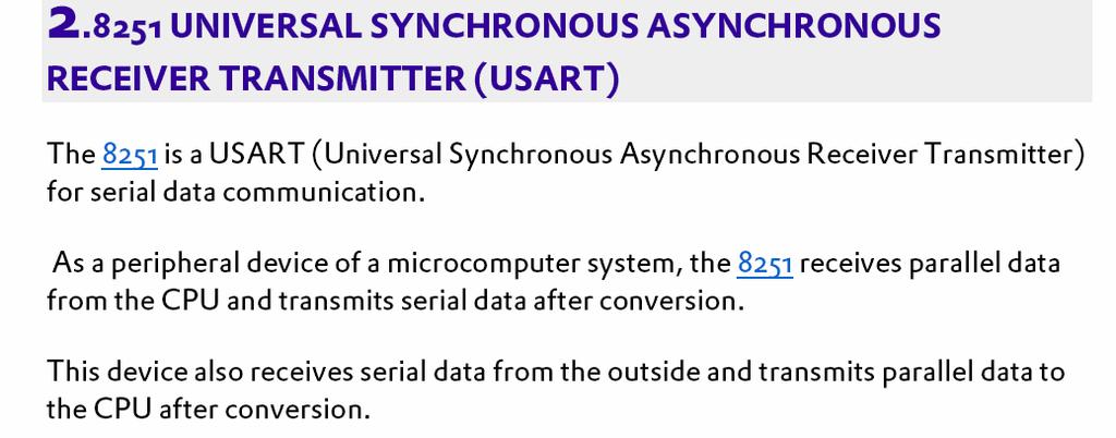
 Experiment 6 Interfacing a Hyper Terminal to the Flight 86 Kit Objective The aim of this lab experiment is to interface a Hyper Terminal to 8086 processor by programming the 8251 USART. Equipment Flight
2. List the five interrupt pins available in INTR, TRAP, RST 7.5, RST 6.5, RST 5.5.
 DHANALAKSHMI COLLEGE OF ENGINEERING DEPARTMENT OF ELECTRICAL AND ELECTRONICS ENGINEERING EE6502- MICROPROCESSORS AND MICROCONTROLLERS UNIT I: 8085 PROCESSOR PART A 1. What is the need for ALE signal in
 VALLIAMMAI ENGINEERING COLLEGE S.R.M. NAGAR, KATTANKULATHUR-603203. DEPARTMENT OF ELECTRICAL AND ELECTRONICS ENGINEERING VII-EEE EE6502- MICROPROCESSORS AND MICROCONTROLLERS QUESTION BANK UNIT I 1. What
VALLIAMMAI ENGINEERING COLLEGE
 VALLIAMMAI ENGINEERING COLLEGE SRM Nagar, Kattankulathur 603 203 DEPARTMENT OF ELECTRICAL AND ELECTRONICS ENGINEERING QUESTION BANK V SEMESTER EE6502- MICROPROCESSORS AND MICROCONTROLLERS Regulation 2013
Control Unit: The control unit provides the necessary timing and control Microprocessor resembles a CPU exactly.
 Unit I 8085 and 8086 PROCESSOR Introduction to microprocessor A microprocessor is a clock-driven semiconductor device consisting of electronic logic circuits manufactured by using either a large-scale
MAHALAKSHMI ENGINEERING COLLEGE TIRUCHIRAPALLI UNIT IV I/O INTERFACING PART A (2 Marks)
") MAHALAKSHMI ENGINEERING COLLEGE TIRUCHIRAPALLI-621213. UNIT IV I/O INTERFACING PART A (2 Marks) 1. Name the three modes used by the DMA processor to transfer data? [NOV/DEC 2006] Signal transfer mode (cycling
MAHALAKSHMI ENGINEERING COLLEGE TIRUCHIRAPALLI-621213. UNIT IV I/O INTERFACING PART A (2 Marks) 1. Name the three modes used by the DMA processor to transfer data? [NOV/DEC 2006] Signal transfer mode (cycling
Pin Description, Status & Control Signals of 8085 Microprocessor
 Pin Description, Status & Control Signals of 8085 Microprocessor 1 Intel 8085 CPU Block Diagram 2 The 8085 Block Diagram Registers hold temporary data. Instruction register (IR) holds the currently executing
DEPARTMENT OF ECE QUESTION BANK SUBJECT: MICROPROCESSOR AND MICROCONTROLLER UNIT-1 PART-A (2 MARKS)
") DEPARTMENT OF ECE QUESTION BANK SUBJECT: MICROPROCESSOR AND MICROCONTROLLER CODE: EC6504 UNIT-1 1. How many memory locations are available in 8086 microprocessor? 2. What are the flags available in 8086
DEPARTMENT OF ECE QUESTION BANK SUBJECT: MICROPROCESSOR AND MICROCONTROLLER CODE: EC6504 UNIT-1 1. How many memory locations are available in 8086 microprocessor? 2. What are the flags available in 8086
Lecture-50 Intel 8255A: Programming and Operating Modes
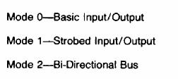
 Lecture-50 Intel 8255A: Programming and Operating Modes Operation Description: There are three basic modes of operation that can be selected by the system software. Mode 0: Basic Input/output Mode 1: Strobes
1 MALP ( ) Unit-1. (1) Draw and explain the internal architecture of 8085.
 Unit-1. (1) Draw and explain the internal architecture of 8085.") (1) Draw and explain the internal architecture of 8085. The architecture of 8085 Microprocessor is shown in figure given below. The internal architecture of 8085 includes following section ALU-Arithmetic
(1) Draw and explain the internal architecture of 8085. The architecture of 8085 Microprocessor is shown in figure given below. The internal architecture of 8085 includes following section ALU-Arithmetic
DHANALAKSHMI COLLEGE OF ENGINEERING DEPARTMENT OF ELECTRICAL AND ELECTRONICS ENGINEERING YEAR : III SEM : VI
 DHANALAKSHMI COLLEGE OF ENGINEERING DEPARTMENT OF ELECTRICAL AND ELECTRONICS ENGINEERING YEAR : III SEM : VI EE2354- MICROPROCESSORS AND MICROCONTROLLER UNIT I 8085 and 8086 PROCESSOR PART A 1. Define
This set of Microprocessor Multiple Choice Questions & Answers (MCQs) focuses on PIO 8255 (Programmable Input Output Port).
 focuses on PIO 8255 (Programmable Input Output Port).") This set of Microprocessor Multiple Choice Questions & Answers (MCQs) focuses on PIO 8255 (Programmable Input Output Port). 1. Programmable peripheral input-output port is other name for a) serial input-output
This set of Microprocessor Multiple Choice Questions & Answers (MCQs) focuses on PIO 8255 (Programmable Input Output Port). 1. Programmable peripheral input-output port is other name for a) serial input-output
Summer 2003 Lecture 21 07/15/03
 Summer 2003 Lecture 21 07/15/03 Simple I/O Devices Simple i/o hardware generally refers to simple input or output ports. These devices generally accept external logic signals as input and allow the CPU
A VHDL 8254 Timer core
 An www.opencores.org Project hlefevre@opencores.org Revision History Revision Date Author Description 0.1 3 Aug 2008 H LeFevre Initial Release of source files 0.5 4 Aug 2008 H LeFevre Add info about Timer
Microcontroller interfaces
 Microcontroller interfaces 1 Microcontroller interfaces Microcontroller interfaces Digital Analog Serial Parallel Binary (on/off) Voltage Current Asynchronous Synchronous 1-wire RS232/485 Ethernet 2-wire
Question Bank Microprocessor and Microcontroller
 QUESTION BANK - 2 PART A 1. What is cycle stealing? (K1-CO3) During any given bus cycle, one of the system components connected to the system bus is given control of the bus. This component is said to
 www.vidyarthiplus.com www.vidyarthiplus.com www.vidyarthiplus.com www.vidyarthiplus.com www.vidyarthiplus.com Time : Three hours Reg. No. : B.E./B.Tech. DEGREE EXAMINATION, APRIL/MAY 2011 Sixth
MICROPROCESSOR AND MICROCONTROLLER BASED SYSTEMS
 MICROPROCESSOR AND MICROCONTROLLER BASED SYSTEMS UNIT I INTRODUCTION TO 8085 8085 Microprocessor - Architecture and its operation, Concept of instruction execution and timing diagrams, fundamentals of
UNIT III. 2. Non-maskable interrupts. 3. Software interrupt. 4. Internal interrupt
 UNIT III 8086 INTERRUPTS: An interrupt is the method of processing the microprocessor by peripheral device. An interrupt is used to cause a temporary halt in the execution of program. Microprocessor responds
AE66/AC66/AT66/ AE108/AC108/AT108 MICROPROCESSORS & MICROCONTROLLERS
 Q.2 a. Draw pin diagram and signal group diagram of 8085 microprocessor. (8) b. List out the various categories of the 8085 instructions. Give examples of the instructions for each group. (8) Data transfer
MICROPROCESSORS & MICRO CONTROLLER COLLEGE OF ENGINEERING DEPARTMENT OF COMPUTER SCIENCE AND ENGINEERING QUESTION BANK
 KINGS COLLEGE OF ENGINEERING DEPARTMENT OF COMPUTER SCIENCE AND ENGINEERING QUESTION BANK SUBJECT CODE: EC1257 SUBJECT NAME: MICROPROCESSOR AND MICROCONTROLLER YEAR : II IT SEM : IV UNIT I THE 8085 MICROPROCESSOR
EC6504 MICROPROCESSOR AND MICROCONTROLLER QUESTION BANK UNIT I - THE 8086 MICROPROCESSOR PART A
 EC6504 MICROPROCESSOR AND MICROCONTROLLER Question Bank EC6504 MICROPROCESSOR AND MICROCONTROLLER QUESTION BANK UNIT I - THE 8086 MICROPROCESSOR 1. List the addressing modes of 8086?give examples [May
Architecture of 8085 microprocessor
 Architecture of 8085 microprocessor 8085 consists of various units and each unit performs its own functions. The various units of a microprocessor are listed below Accumulator Arithmetic and logic Unit
Microprocessors and Microcontrollers (EE-231)
") Microprocessors and Microcontrollers (EE-231) Main Objectives 8088 and 80188 8-bit Memory Interface 8086 t0 80386SX 16-bit Memory Interface I/O Interfacing I/O Address Decoding More on Address Decoding
Microprocessors and Microcontrollers (EE-231) Main Objectives 8088 and 80188 8-bit Memory Interface 8086 t0 80386SX 16-bit Memory Interface I/O Interfacing I/O Address Decoding More on Address Decoding
PART - B (Answer all five units, 5 X 10 = 50 Marks)
") Code: 13A04507 R13 B.Tech III Year I Semester (R13) Supplementary Examinations June 2017 MICROPROCESSS & INTERFACING (Common to CSE & IT) PART - A (a) Mention the function of the instruction ADD M of 8085
Code: 13A04507 R13 B.Tech III Year I Semester (R13) Supplementary Examinations June 2017 MICROPROCESSS & INTERFACING (Common to CSE & IT) PART - A (a) Mention the function of the instruction ADD M of 8085
Address connections Data connections Selection connections
 Interface (cont..) We have four common types of memory: Read only memory ( ROM ) Flash memory ( EEPROM ) Static Random access memory ( SARAM ) Dynamic Random access memory ( DRAM ). Pin connections common
CENG-336 Introduction to Embedded Systems Development. Timers
 CENG-336 Introduction to Embedded Systems Development Timers Definitions A counter counts (possibly asynchronous) input pulses from an external signal A timer counts pulses of a fixed, known frequency
8255 Programmable Peripheral Interface Architecture MCT/UNIT III/NARASIMHARAJ/LECTURE NOTES /IV MECH A
 8255 Programmable Peripheral Interface Architecture 8255 PPI Architecture The parallel input-output port chip 8255 is also called as programmable peripheral input- output port. The Intel s 8255 is designed
QUESTION BANK CS2252 MICROPROCESSOR AND MICROCONTROLLERS
 FATIMA MICHAEL COLLEGE OF ENGINEERING & TECHNOLOGY Senkottai Village, Madurai Sivagangai Main Road, Madurai -625 020 QUESTION BANK CS2252 MICROPROCESSOR AND MICROCONTROLLERS UNIT 1 - THE 8085 AND 8086
EC1362 Microprocessors & Microcontrollers
 Part A- Two Mark Questions 1. What is Microprocessor? It is a program controlled semiconductor device (IC}, which fetches, decodes and executes instructions. 2. What are the basic units of a microprocessor?
MAHARASHTRA STATE BOARD OF TECHNICAL EDUCATION (Autonomous) (ISO/IEC Certified) MODEL ANSWER
 (ISO/IEC Certified) MODEL ANSWER") MODEL ANSWER SUMMER 17 EXAMINATION Subject Title: Microprocessor Subject Code: 17443 I m p o r t a n t I n s t r u c t i o n s t o e x a m i n e r s : 1) The answers should be examined by key words and
MODEL ANSWER SUMMER 17 EXAMINATION Subject Title: Microprocessor Subject Code: 17443 I m p o r t a n t I n s t r u c t i o n s t o e x a m i n e r s : 1) The answers should be examined by key words and
VALLIAMMAI ENGINEERING COLLEGE. SRM Nagar, Kattankulathur DEPARTMENT OF COMPUTER SCIENCE ENGINEERING
 VALLIAMMAI ENGINEERING COLLEGE SRM Nagar, Kattankulathur-603 203 DEPARTMENT OF COMPUTER SCIENCE ENGINEERING EC6504 MICROPROCESSOR AND MICROCONTROLLER YEAR / SEMESTER: II / IV ACADEMIC YEAR: 2015-2016 (EVEN
NuDAQ ACL-7120A. Digital I/O & Timer/Counter Card User s Guide
 NuDAQ ACL-7120A Digital I/O & Timer/Counter Card User s Guide Copyright 1995, 2003 ADLINK TECHNOLOGY INC. All Rights Reserved. Manual Rev. 1.00: May 30, 2003 Part No: 50-11031-100 The information in this
 EASWARI ENGINEERING COLLEGE DEPARTMENT OF ELECTRONICS AND COMMUNICATION QUESTION BANK - V SEMESTER ECE EC2304 MICROPROCESSORS AND MICROCONTROLLERS UNIT I 1. When the 8086 processor is in minimum mode and
DM5806/DM6806 User s Manual
 DM5806/DM6806 User s Manual Real Time Devices USA, Inc. Accessing the Analog World Publication No. 5806-8/18/99 DM5806 / DM6806 User s Manual REAL TIME DEVICES USA, INC. Post Office Box 906 State College,
University of Alexandria Faculty of Engineering Division of Communications & Electronics
 University of Alexandria Faculty of Engineering Division of Communications & Electronics Subject Name: Microprocessors Lecturer: Dr. Mohammed Morsy Academic Year: 2012 2013 Assistants: Eng. Ahmed Bedewy
Segment A Programmable Peripheral Interface (PPI)
") Segment 6 8255A Programmable Peripheral Interface (PPI) Content Why 8255A? Handshaking and Handshaking Signal Parallel Data Transfer 8255A Internal Block Diagram Description of 8255A Internal Block Diagram
Segment 6 8255A Programmable Peripheral Interface (PPI) Content Why 8255A? Handshaking and Handshaking Signal Parallel Data Transfer 8255A Internal Block Diagram Description of 8255A Internal Block Diagram
Understanding the basic building blocks of a microcontroller device in general. Knows the terminologies like embedded and external memory devices,
 Understanding the basic building blocks of a microcontroller device in general. Knows the terminologies like embedded and external memory devices, CISC and RISC processors etc. Knows the architecture and
8085 Microprocessor Architecture and Memory Interfacing. Microprocessor and Microcontroller Interfacing
 8085 Microprocessor Architecture and Memory 1 Points to be Discussed 8085 Microprocessor 8085 Microprocessor (CPU) Block Diagram Control & Status Signals Interrupt Signals 8085 Microprocessor Signal Flow
QUESTION BANK. EE 6502 / Microprocessor and Microcontroller. Unit I Processor. PART-A (2-Marks)
") QUESTION BANK EE 6502 / Microprocessor and Microcontroller Unit I- 8085 Processor PART-A (2-Marks) YEAR/SEM : III/V 1. What is meant by Level triggered interrupt? Which are the interrupts in 8085 level
QUESTION BANK EE 6502 / Microprocessor and Microcontroller Unit I- 8085 Processor PART-A (2-Marks) YEAR/SEM : III/V 1. What is meant by Level triggered interrupt? Which are the interrupts in 8085 level
CPE/EE 421/521 Fall 2004 Chapter 4 The CPU Hardware Model. Dr. Rhonda Kay Gaede UAH. The CPU Hardware Model - Overview
 CPE/EE 421/521 Fall 2004 Chapter 4 The 68000 CPU Hardware Model Dr. Rhonda Kay Gaede UAH Fall 2004 1 The 68000 CPU Hardware Model - Overview 68000 interface Timing diagram Minimal configuration using the
SANKALCHAND PATEL COLLEGE OF ENGINEERING, VISNAGAR. ELECTRONICS & COMMUNICATION DEPARTMENT Question Bank- 1
 SANKALCHAND PATEL COLLEGE OF ENGINEERING, VISNAGAR ELECTRONICS & COMMUNICATION DEPARTMENT Question Bank- 1 Subject: Microcontroller and Interfacing (151001) Class: B.E.Sem V (EC-I & II) Q-1 Explain RISC
1. INTRODUCTION TO MICROPROCESSOR AND MICROCOMPUTER ARCHITECTURE:
 1. INTRODUCTION TO MICROPROCESSOR AND MICROCOMPUTER ARCHITECTURE: A microprocessor is a programmable electronics chip that has computing and decision making capabilities similar to central processing unit
UNIT.4. Syllabus I/O INTERFACING 8085
 UNIT.4 I/O INTERFACING 8085 Syllabus Memory Interfacing and I/O interfacing Parallel communication interface Serial communication interface Timer Keyboard /display controller Interrupt controller DMA controller
Lecture-9 Intel 8085 Microprocessor It is a 40-pin DIP(Dual in package) chip, base on NMOS technology, on a single chip of silicon.
 chip, base on NMOS technology, on a single chip of silicon.") Lecture-9 Intel 8085 Microprocessor It is a 40-pin DIP(Dual in package) chip, base on NMOS technology, on a single chip of silicon. It requires a single +5v supply between Vcc at pin no 40 and GND at pin
Lecture-9 Intel 8085 Microprocessor It is a 40-pin DIP(Dual in package) chip, base on NMOS technology, on a single chip of silicon. It requires a single +5v supply between Vcc at pin no 40 and GND at pin
BASIC INTERFACING CONCEPTS
 Contents i SYLLABUS UNIT - I 8085 ARCHITECTURE Introduction to Microprocessors and Microcontrollers, 8085 Processor Architecture, Internal Operations, Instructions and Timings, Programming the 8085-Introduction
The IIC interface based on ATmega8 realizes the applications of PS/2 keyboard/mouse in the system
 Available online at www.sciencedirect.com Procedia Engineering 16 (2011 ) 673 678 International Workshop on Automobile, Power and Energy Engineering The IIC interface based on ATmega8 realizes the applications
EC6504-MP&MC, UNIT3 Page 1
 Year/sem: 02/04 UNIT III I/O INTERFACING Academic Year: 2014-2015 (even) 1. What is interfacing? An interface is a shared boundary between the devices which involves sharing information. Interfacing is
Code No: Set No. 1
 Code No: 2320404 Set No. 1 1. a) Draw the architectural diagram of 8085 and explain the function of each block in detail b) Discuss about Multiplexing in 8086 microprocessor [10+6] 2. a) Explain in detail
KINGS DEPARTMENT OF INFORMATION TECHNOLOGY QUESTION BANK. Subject Name: Microprocessors and Microcontrollers UNIT-I 8085 MICROPROCESSOR
 KINGS COLLEGE OF ENGINEERING DEPARTMENT OF INFORMATION TECHNOLOGY QUESTION BANK Subject Name: Microprocessors and Microcontrollers Year/Sem: II/IV UNIT-I 8085 MICROPROCESSOR PART-A (2 MARKS) 1. Name the
Chapter 13 Direct Memory Access and DMA-Controlled I/O
 Chapter 13 Direct Memory Access and DMA-Controlled I/O The DMA I/O technique provides direct access to the memory while the microprocessor is temporarily disabled This allows data to be transferred between
Microcomputer System Design
 Microcomputer System Design COE305 Lab. What is a Microprocessor? A microprocessor is a multipurpose, clockdriven, register-based electronic device that reads binary instructions from a storage device
UNIT-IV. The semiconductor memories are organized as two-dimensional arrays of memory locations.
 UNIT-IV MEMORY INTERFACING WITH 8086: The semi conductor memories are of two types: Static RAM Dynamic RAM The semiconductor memories are organized as two-dimensional arrays of memory locations. For Ex:
MICROPROCESSOR TECHNOLOGY
 MICROPROCESSOR TECHNOLOGY Assis. Prof. Hossam El-Din Moustafa Lecture 14 Ch.6 The 80186, 80188, and 80286 Microprocessors 21-Apr-15 1 Timers The 80186/80188 contain three fully programmable 16-bit timers
Microcontroller and Embedded Systems:
 Microcontroller and Embedded Systems: Branches: 1. Electronics & Telecommunication Engineering 2. Electrical & Electronics Engineering Semester: 6 th Semester / 7 th Semester 1. Explain the differences
Department of Computer Science and Engineering
 Department of Computer Science and Engineering QUESTION BANK Subcode/Subject : CS1304 Microprocessor & Microcontroller Year/Sem: III / V UNIT I THE 8085 MICROPROCESSOR PART A ( 2Marks) 1. How AD0-AD7 are
EC6504 MICROPROCESSOR AND MICROCONTROLLER
 UNIT I THE 8086 MICROPROCESSOR 1. What do you mean by Addressing modes? (May/June 2014) The different ways that a microprocessor can access data are referred to as addressing modes. 2. What is meant by
Parallel-to-Serial and Serial-to-Parallel Converters
 Session 1532 Parallel-to-Serial and Serial-to-Parallel Converters Max Rabiee, Ph.D., P.E. University of Cincinnati Abstract: Microprocessors (MPUs) on a computer motherboard communicate in a parallel format
EEM336 Microprocessors I. I/O Interface
 EEM336 Microprocessors I I/O Interface Introduction Basic I/O interface Handshaking process Serial and Parallel communication I/O interface examples 2 Chapter Objectives Upon completion of this chapter,
DE60/DC68 MICROPROCESSORS & MICROCONTROLLERS JUNE 2013
 Q 2 (a) Distinguish between following pair of instructions of 8085 (i) LXI H, 123H and LHLD 1234H (ii) SPHL and PCHL (iii) XRA M and ORA M (iv) RRC and RLC (i)lxi H, 123H- Loads 16 bit data (123H) in register
Department of EIE / Pondicherry Engineering College. Timer/Counters. Department of EIE / Pondicherry Engineering College 1
 Timer/Counters Department of EIE / Pondicherry Engineering College 1 The 8051 has two internal sixteen bit hardware Timer/Counters. Each Timer/Counter can be configured in various modes, typically based
1. Define Peripherals. Explain I/O Bus and Interface Modules. Peripherals: Input-output device attached to the computer are also called peripherals.
 1. Define Peripherals. Explain I/O Bus and Interface Modules. Peripherals: Input-output device attached to the computer are also called peripherals. A typical communication link between the processor and
Chapter 8 Summary: The 8086 Microprocessor and its Memory and Input/Output Interface
 Chapter 8 Summary: The 8086 Microprocessor and its Memory and Input/Output Interface Figure 1-5 Intel Corporation s 8086 Microprocessor. The 8086, announced in 1978, was the first 16-bit microprocessor
1. Internal Architecture of 8085 Microprocessor
 1. Internal Architecture of 8085 Microprocessor Control Unit Generates signals within up to carry out the instruction, which has been decoded. In reality causes certain connections between blocks of the
ROEVER ENGINEERING COLLEGE
 ROEVER ENGINEERING COLLEGE ELAMBALUR, PERAMBALUR- 621 212 DEPARTMENT OF INFORMATION TECHNOLOGY MICROPROCESSOR & MICROCONTROLLER 2 marks questions andanswers Unit I 1. Define microprocessor? A microprocessor
It is a program controlled semiconductor device (IC}, which fetches, decode and executes instructions.
 1.What is Microprocessor? It is a program controlled semiconductor device (IC}, which fetches, decode and executes instructions. 2. What are the basic units of a microprocessor? The basic units or blocks
PIN DIAGRAM. Richa Upadhyay Prabhu. NMIMS s MPSTME January 19, 2016
 PIN DIAGRAM Richa Upadhyay Prabhu NMIMS s MPSTME richa.upadhyay@nmims.edu January 19, 2016 Richa Upadhyay Prabhu (MPSTME) 8080 Microprocessor January 19, 2016 1 / 51 Pin Diagram of 8086 Richa Upadhyay
FIFTH SEMESTER B.TECH DEGREE EXAMINATION MODEL TEST QUESTION PAPER, NOVEMBER CS 305: Microprocessor and Microcontrollers PART A
 Reg No Name FIFTH SEMESTER B.TECH DEGREE EXAMINATION MODEL TEST QUESTION PAPER, NOVEMBER 2017 CS 305: Microprocessor and Microcontrollers Max. Marks: 100 Duration: 3 Hours PART A Answer all questions.
MCS6522 V E R S A T IL E IN T ERFACE A D A PTER
 PRELIMINARY DATA MOS TCCHNOLOOY, INC. VALLEY FORGE CORPORATE CENTER 1216) 666 7950 950 RITTENHOUSE ROAD. NORRISTOWN, PA 19401 SHEET NOVEMBER 1977 MCS6522 V E R S A T IL E IN T ERFACE A D A PTER DESCRIPTION
CHAPTER: 3 PROGRAMMABLE PERIPHERAL INTERFACE & ELECTROMECHANICAL DEVICES INTERFACING
 CHAPTER: 3 1 PROGRAMMABLE PERIPHERAL INTERFACE & ELECTROMECHANICAL DEVICES INTERFACING Introduction to 8255 PPI 2 The Intel 8255A is a high-performance, general purpose programmable I/O device is designed
8051 Microcontroller
 8051 Microcontroller 1 Salient Features (1). 8 bit microcontroller originally developed by Intel in 1980. (2). High-performance CMOS Technology. (3). Contains Total 40 pins. (4). Address bus is of 16 bit