System Level Design For Low Power. Yard. Doç. Dr. Berna Örs Yalçın
|
|
|
- Kristina Casey
- 6 years ago
- Views:
Transcription
1 System Level Design For Low Power Yard. Doç. Dr. Berna Örs Yalçın
2 References System-Level Design Methodology, Daniel D. Gajski Hardware-software co-design of embedded systems : the POLIS approach / by Felice Balarin... [et al.], Boston : Kluwer Academic Publishers, c1997 Embedded System Design, Peter Marwedel, Kluwer Academic Publishers, 2003 Low Power Electronics Design
3 Design Methodologies The designers can only focus their efforts on the level at which the system is comprehensible to them. Complexities of Systems -on-chip rising almost daily The set of specific tasks in design process is called a design methodology. Need a new methodology increased productivity decreased times-to-market. Solution increasing levels of abstraction, or in other words, increasing the size of the basic building blocks. The industry infrastructure which is also supported by separate SW and HW programs created the system gap in which non-compatible SW and HW methodologies are preventing the progress in design of electronic systems.

4
5 Design Flow (1/2) Capture-and-Simulate Methodology (approximately from 1960s to 1980s) Software and hardware design was separated by a system gap. SW designers tested some algorithms and possibly wrote the requirements document and an initial specification. This specification was given to HW designers who read it and started system design with a block diagram. They did not know whether their design will satisfy the specification until the gate level design was captured and simulated. Describe-and-Synthesize methodology (late 1980s to late 1990s) Logic synthesis Designers first specify what they want in terms of Boolean equations or FSM descriptions The synthesis tools generate the implementation in terms of a gate netlist The behavior or the function comes first and the structure or implementation next. There are two models to simulate: behavior (function) and gate-level structure (netlist). Specification comes before implementation and they are both simulatable. It is possible to verify their equivalence since they can be both reduced to a canonical form in principle. Today s designs are too large for this kind of equivalence checking. By late 1990s the logic level has been abstracted to cycle-accurate (RTL) description and synthesis. We have two abstraction levels (RTL and gate levels) and two different models on each level (behavioral and structural). The system gap still persists.
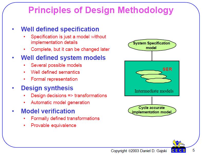
6 Design Flow (2/2) Specify, Explore-and-Refine Methodology (from early 2000s ) In order to close the gap we must increase level of abstraction from RTL to SL. On SL level we have executable specification that represents the system behavior (function) structural models with emphasis on connectivity (communication). Each model is used to prove some system property such as functionality, connectivity, communication and so on. Each model can be considered to be a specification for the next level model in which more detail in implementation is added. Specify-explore-refine (SER) methodology represents a sequence of models in which each model is an refinement of the previous one. SER methodology follows the natural design process where designers specify the intent first, explore possibilities and then refine the model according to their decisions. SER flow can be viewed as several iterations of the basic describe-and-synthesize methodology.
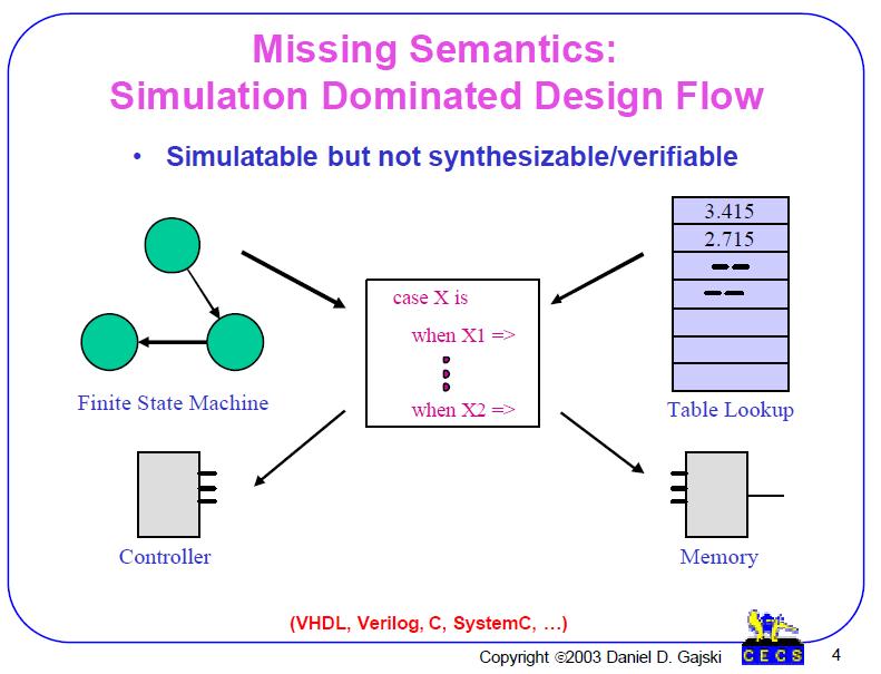
7 Missing Semantics With introduction of SL abstraction, designers have to generate even more models. One obvious solution is to automatically refine one model into another. That requires well defined model semantics, or, in other words, good understanding what is meant by the given model. Design methodologies and EDA industry have been dominated by simulation based methodologies in the past. For example, all HDL (such as Verilog, VHDL, SystemC, and others) are simulatable but not synthetizable or verifiable. A case statement can be used to model a FSM or a look-up table, for example. However, FSMs and look-up tables require different implementations: a FSM can be implemented with a controller a look-up table is implemented with a memory. Therefore, the model which uses case statement to model FSMs and tables is good for simulation not good for implementation since a designer does not know what was really described by the case statement. Thus, clean and unambigues semantics is needed for refinement, synthesis and verification. Such a clean semantics is missing from most of the simulation-oriented languages.
8
9
10
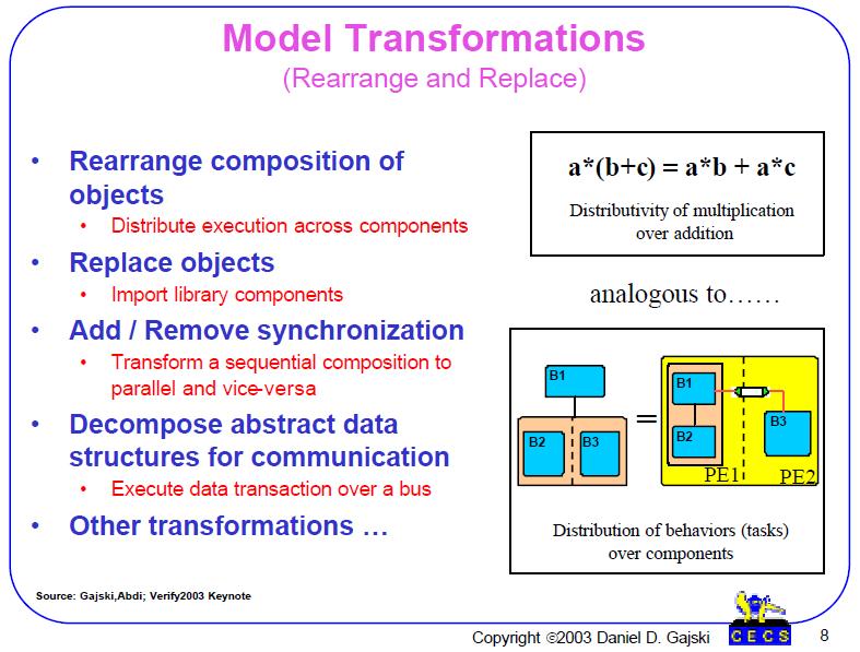
11 While transformations are small and not significant changes in a model, a refinement, on the other hand, modifies the model dramatically by exposing a different aspect or characteristic of the design.

12
13 Model Definition A model is a set of objects and a set of composition rules defined on those objects. A specification level model objects like behaviors for computation channels for communication An architecture model components such as processors, memories, IPs for computation buses for communication. Composition rules combine objects into larger objects and create hierarchical structures. A model algebra represents the set of all possible models that use the same set of objects and composition rules. Such a set of all possible models is infinite. A specific model is defined by a set of relations (one relation per each composition rule) which define which objects are related by the particular composition rule in the given model.
14
15
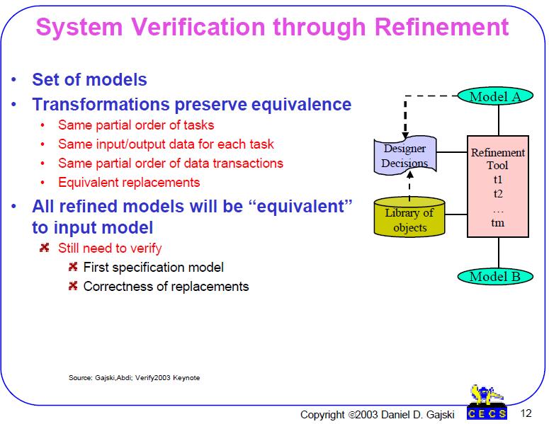
16 Refinement- based methodology Any design flow or design methodology can be described by a set of models and the corresponding set of refinements of one model into another. Since each model refinement is well defined sequence of transformations, each refinement can be automated. If each refinement is automated, then each model can be automatically generated.
17 Refinement- based methodology If models are automatically generated then designers do not need to write different design models except the original specification model. If designers do not write models then there is no need for different modeling languages. In other words, designers only make design decisions, while every design decision is automatically applied through corresponding model transformation.
18 System Synthesis through Refinement Synthesis is the process of converting the functional description of a black box into a structure of the black box that consists of connected components from a given library. During this process we must make several different design decisions selecting components and their connectivity, Mapping computation and communication constructs to components ordering or scheduling computations or communications of different messages adding new objects inserting synchronization to preserve dependences
19 System Synthesis through Refinement The design process is a sequence o f such design decisions. Since for every design decision there is a model transformation, a sequence of design decisions will result in a sequence of transformations or model refinement. Synthesis = design + refinement The main challenge for every application today is to define the appropriate set of models and corresponding refinements for every refinement, the sequence of design decisions and corresponding model transformations.
20
21
22 Y-Chart Y-Chart makes the assumption that each design can be modeled in three basic ways that emphasize different properties of the same design. Y-Chart has three axes that represent design behavior (function, specification) design structure (netlist, block diagram) physical design (layout, boards, packages). Behavior represents a design as a black box and describes its outputs in terms of its inputs and time. The black-box behavior does not indicate in anyway how to implement the black box or what its structure is. In the structure axis, black box is represented as a set of components and connections. Although, behavior of the black box can be derived from its component behaviors such behavior may be difficult to understand. Physical design adds dimensionality to the structure. It specifies size (height and width) of each component, the position of each component, each port and each connection on the silicon substrate or board or any other container. Y-Chart can also represent design on different abstraction levels identified by concentric circles around the origin. Each abstraction level uses different time granularity. Usually, four levels are identified: Circuit Logic Processor System levels.
23 Y-Chart The abstraction level can be also identified by the main component used in the structure.the main components on Circuit level are N or P-type transistors Logic level they are gates and flip-flops Processor level the main components are storage units such as register files and functional units such as ALUs System level they are processors, memories and buses Converting behavior into structure on each abstraction level is called synthesis, and the structure into layout is called physical design. Each abstraction level needs also a database of components on this level. Each component in the database has tree models representing three different axes in the Y-Chart: behavior or function (sometimes called Model of Computation (MoC)) structure of components from the lower level of abstraction physical layout or implementation of the structure. These components are IPs for each abstraction level.
24 Example A system which can add or multiply two 32-bit numbers Behavioral representation: Structural representation: Several interconnected registers Arithmetic units Multiplexors and Focus : functional correctness create better products when working with behavioral respresentation
25 Levels of Abstraction
26
27 Finite State Machine r1/n r2/n start r1/d1 f 1 f 2 r2/u1 r1/d2 r3/u2 r3/u1 r2/d1 f 3 r3/n
28 Finite State Machine States A set of transitions A set of actions <S, I, O, f : S I S, h : S I O> Set of states : S={s 1,s 2,,s n } Set of inputs : I={i 1,i 2,,i m } Set of outputs : O={o 1,o 2,,o k } Next state function : f Output function : h
29 Meally and Moore Machines Transition based (Mealy) : h : S I O State based (Moore) : h : S O
30 Views of an Elevator Controller If the elevator is stationary and the floor requested is equal to the current floor, then the elevator remains idle. If the elevator is stationary and the floor requested is less than the current floor, then lower the elevator to the requested floor. If the elevator is stationary and the floor requested is greater than the current floor, then raise the elevator to the requested floor. loop if (req_floor = curr_floor) then direction := idle; elsif (req_floor < curr_floor) then direction := down; elsif (req_floor > curr_floor) then direction := up; end if; end loop; req_floor < curr_floor direction := down req_floor = curr_floor direction := idle req_floor > curr_floor direction := up req_floor < curr_floor direction := down Down Idle Up req_floor = curr_floor direction := idle req_floor = curr_floor direction := idle req_floor > curr_floor direction := up
31 r1 r1 r2 r3 start f1/n f2/n f3/n r2 r2 r3 r3 r1 r2 r2 r3 r1 f1/u1 r1 r3 f2/u1 r3 r2 f3/d1 r2 r1 r1 r1 f1/u2 f2/d1 r2 f3/d2 r3 r1 r3 r2 r3
32 FSM with Data Path Curr_floor!=req_floor/output:=req_floor-curr_floor; curr_floor:=req_floor start S 1 Curr_floor=req_floor/output:=0 <S, I STAT, O A, f, h> A set of storage variables : VAR A set of expressions : EXP={ f(x, y, z, ) x, y, z, VAR } A set of storage assignments : A={ X e X VAR, e EXP } A set of status expressions : STAT={ Rel(a, b) a, b EXP} f : S (I STAT) S h : S (I STAT) (O A)
33 Architecture After appropriate model transform the model into an architecture req_floor curr_floor State register Combinational logic direction req_floor curr_floor processor In/out ports Bus memory direction
34 Activity Oriented Models Dataflow Graph For transformational systems : outputs are determined by a set of computations on the system s inputs No states Activities and dataflow between them
35 DFG : A set of nodes and edges Input X A 1 A 2 Y V File V Z W Output Output Data store : records in a database, a file, a variable in a memory, a register Activity : a program, a procedure, a function, one intruction, one arithmetic operation Data being transmitted Supports hierarchy, since each activity node can be represented by another DFG Does not contain any information about implementation
36 Heterogeneous Models Control / data flow graph (CDFG) DFG : represent data flow among activities CFG : represent the squencing of the DFGs start stop Stop/disable A 2, disable A 3 S 0 S 1 S 2 Start/enable A 1, enable A 2 W=10 / disable A 1, enable A 3 control W = 10 disable enable W disable enable A 2 disable enable Z A 1 X Y A 3
37 Control-Data Flow Graph (CDFG) Programming languages consist of if statements, loops, and expressions. In each of the then or else parts, the if statement computes a set of expressions called a Basic Block (BB). The if statement can also be used in the loop construct to represent loop iterations. Any programming-language code can be represented by a CDFG consisting of if diamonds, which represent if conditions, and BB blocks, which represent computation.
38 Flowcharts : A set of nodes and arcs start J=1 Max=0 J=J+1 No Computation : a sequence of assignment statements Decision : control branching J>N No MEM(J)>MAX Yes MAX=MEM(J) Yes end Arcs for control flow
39 Instruction Set (IS) flow chart describes the fetch, decode, and execute stages of each instruction. The fetch stage consists of fetching the new instruction into the Instruction Register (IR) and incrementing the Program Counter. In the decode stage, we decode the type and mode of the fetched instruction. Four types of instructions: register, memory, branch, and miscellaneous instructions. In the case of memory instructions, there are four modes: immediate, direct, relative, and indirect. Each mode contains load and store instructions. Each instruction execution is in turn described by a BB, which may take several clock cycles to execute, depending on the processor implementation structure.

40
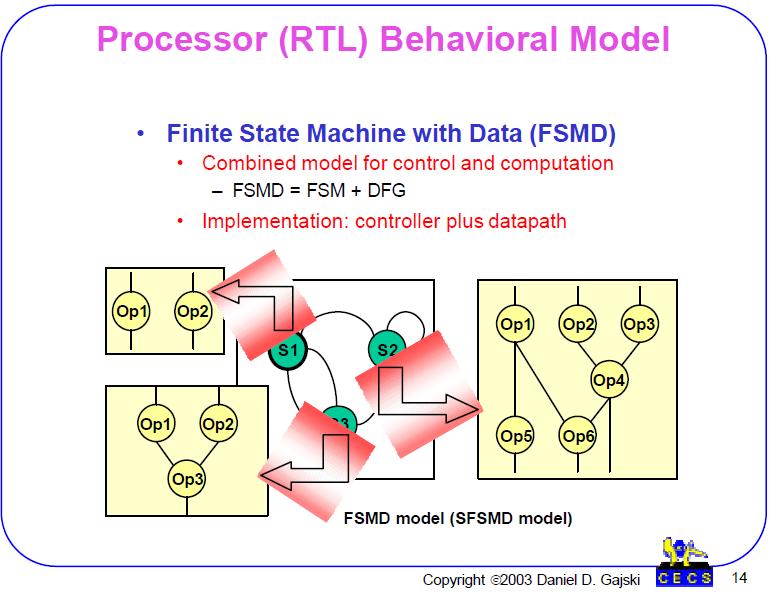
41 Processor Structural Model Consists of a Datapath and a Controller. Datapath executes the DFG attached to each state in the FSMD model. The Datapath has storage units such as Registers, register files, caches and memories, function units such as ALUs, multipliers, shifters, connection units such as buses. Each unit may take one or several clock cycles to produce output. can be pipelined through several stages. may have input and output latches or registers.. can be connected to any of the buses. The above flexibility can be used to pipeline the entire Datapath which comes useful when processing instruction streams in RISC/CISC processors or control streams in NISC/RTL processors. The Controller keeps track of the presents state, defines the next state and controls the execution of the Datapath in each state. Its implementation defines the type of the processor.
42
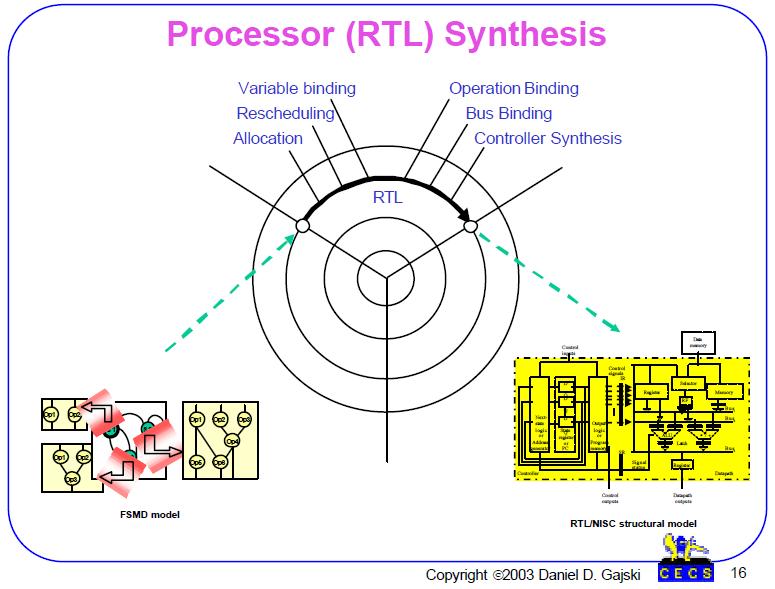
43 Processor /RTL Synthesis consists in converting a FSMD model into a RTL/NISC/RISC/CISC processor that generates the same result as the model. consists of several tasks; a) Allocation of components from the RT library and definition of the Datapath, b) Rescheduling of computation in each state since some components may need more than one clock cycle, c) Binding of variables, operations and register transfers to storage elements, functional units and busses in the Datapath, d) Synthesis of hardwired or programmable controller for RTL/ NISC/RISC/CISC. Generation of refined model representing the Processor structure. For example, the statement a = b + c executing in state (n) can be written: 1) without any binding: a = b + c; 2) with storage binding of a to RF(1), b to RF(3), and c to RF(4): RF(1) = RF(3) + RF(4); 3) with storage and functional unit binding with + bound to ALU1: RF(1) = ALU1(+,RF(3),RF(4)); 4) with storage, functional unit, and connectivity binding: Bus1 = RF(3); Bus2 = RF(4); Bus3 = ALU1 (+,Bus1,Bus2); RF(1) = Bus3; Any of the tasks (a)-(d) can be done in parallel or in any order. If the structure of Controller and Datapath are fixed as in case of RISC/CISC processors then the compiler converts a FSMD model into an instruction stream. Those instructions are loaded into the Programmable memory. If the above tasks are performed automatically, we call the above process RTL synthesis or Behavioral synthesis. In this case many register transfers can be performed in each state of the FSMD model. In this case the RTL/NISC synthesizer generates the control words that can be loaded into programmable memory or implemented with logic gates.
44 System Level Methodology (1/2) Specifying the system s functionality in the earliest stage of the process Advantages to work with an executable specification : Capture the product s functionality Used by marketing departments to study the competitiveness Documentation during all steps of the design process Automatic verification of different design properties Automation of design exploration and synthesis Starting point for all the product upgrades
45 System Level Methodology (2/2) Select a language for writing these specification Must allow an easy exploration of design alternatives Specification must then be partitioned into software and hardware parts Estimate the quality metrics and compare with the requirements
46 Models and Architectures The system = collection of simpler subsystems or pieces There are different methods of decomposing functionality A particular method = a model
47
48 System Behavioral (Functional) Model Since systems consists of many communicating components (processors, IPs) the FSMD model will not be able to model a system since it uses a single thread of execution. The easiest way is to retain the concept of states and transitions as in a FSMD model but to extend the computation in each state to include one or more processes described in a programming language such as C/C++. In order to represent an architecture with several processes running in parallel or in pipelined mode the system model should support concurrency (several components running in parallel) and pipelining (several components running in parallel with data passed between them sequentially). Since components are running concurrently we need a synchronization mechanism for data exchange. a concept of channel to encapsulate data communication. to support hierarchy to allow humans to write easily complex systems specifications. Such a model is called Program State Machine (PSM).
49 Hierarchical Concurrent Finite State Machine (HCFSM) Each set can be decomposed into a set of substates : hierarchy Each set can be decomposed into a set of concurrent substates : execute in parallel Language for HCFSM : Statecharts Ref: David Harel, Statecharts: A visual formalism for complex systems, Science of Computer Programming, Volume 8, Issue 3 (June 1987), Pages:
50
51 System-level structural model Arbitrary components (Proc., IP, Memory) Arbitrary connectivity (buses, protocols)
52 Structure oriented models : Component-connectivity diagram Models systems structural view Often used in the later phases of the design process Program memory Data memory components Processor System bus I/O coprocessor Application specific hardware Connections : buses, wires System block diagram
53 System Structural Model consists of variety of system components such as processors, IPs, memories, arbiters and special application-specific custom hardware components (RTL processors). They can be connected through different connection components such as buses with specific bus protocols. In case that component and bus protocol do not match there must be specific Interface (IF) for connecting such components with incompatible protocols. System structural model a composition of system computation and connection components; any system can be modeled with such a model.
54 Systems Base hardware platform Computational units Communication channels Memory units Peripheral devices Displays Wireless local area networks camcorders
55 System synthesis
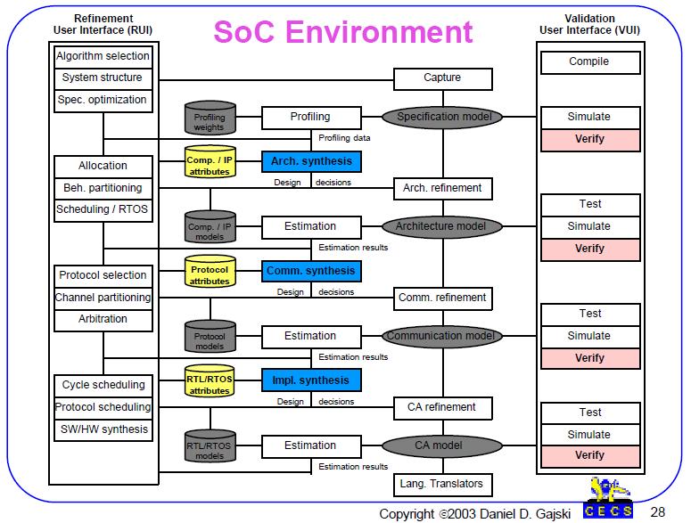
56 System Synthesis PSM model can be synthesized into a arbitrary system structure by the following set of tasks: a) Profiling of code in each behavioral model and collecting statistics about computation, communication, storage,traffic, power consumption, etc., b) Allocating components from the library of processors, memories, IPs and custom components/processors, c) Binding PSM processes to processing elements, variables to storage elements (local and global), and channels to busses, d) Synthesizing interfaces (IFs) between components and busses with incompatible protocols, and inserting arbiters, interrupt controllers, memory controllers, timers, and other special components. e) Refining the PSM model into a architecture model that reflect allocation and binding decisions. The above tasks can be performed automatically or manually. Tasks (b)-(d) are usually performed by designers while tasks (a) and (e) are better done automatically since they require lots of mundane effort. Once the refinement is performed the structural model can be validated by simulation quite efficiently since all the component behaviors are described by high level functions. In order to accomplish all the above tasks, we may use several intermediate models on the way to reach the system structural model from behavioral model.
57
58 System-level Models can be distinguished by the accuracy of timing for their communication and computation. In the graph, the two axes represent the granularity of communication and computation. The functional specification at the origin is untimed, with only a causal ordering between tasks. The spectrum is the cycle accurate model represented by the FSMD model. A system level methodology takes the untimed specification to its cycle accurate implementation. The path through the intermediate models determines different types of refinements that must be performed.
59 System-level Models a) Specication Model (SM) is used by application designers to prove that their algorithms work on a given system platform. They also modify it for more efficient task and channel partitioning, mapping, and scheduling once a possible platform is defined. This model is also used for adding new features, functions, and upgrades after the initial deployment of the product into the market. b) Transaction-Level Model (TLM) is used by system designers to estimate design metrics (such as performance, cost, traffic, communication, power consumption, reliability, among others) and to explore different implementations (component selection, connectivity, system firmware, operating system selection, and different types of interfaces). c) Cycle-Accurate Model (CAM) is used by HW designers to verify the correctness of the generated system HW components (such as custom processors, interfaces, memory controllers, interrupt controllers, bridges, arbiters, and similar components) and by SW designers to verify the system firmware (such as task scheduling, data transfer, synchronization, interrupt procedures, and routing).
60
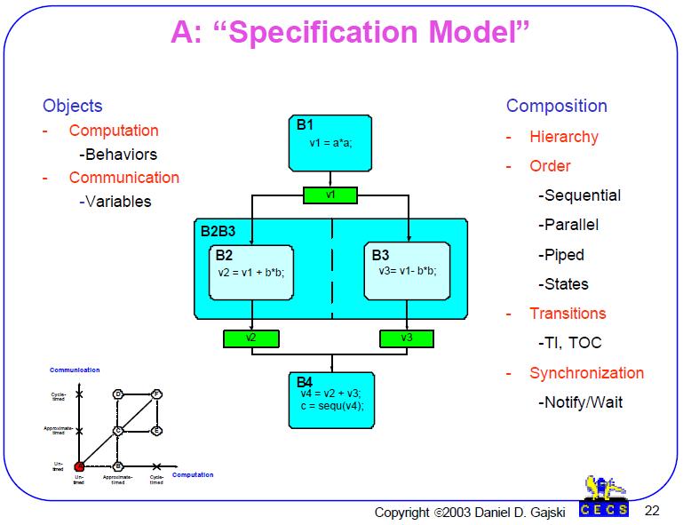
61 Specification Model is an untimed model consisting of objects and composition rules for building larger objects. The objects can be used for computation and communication. Computation objects are behaviors or processes in the PSM model while variables are used for communication of data between behaviors. Composition rules allow construction of larger objects by using hierarchical encapsulation, and ordering of objects in sequential, parallel, pipelined or state fashion. Transitions are used to specify the condition for execution of different behaviors, while synchronizations are used to insure that data are available at proper times.
62
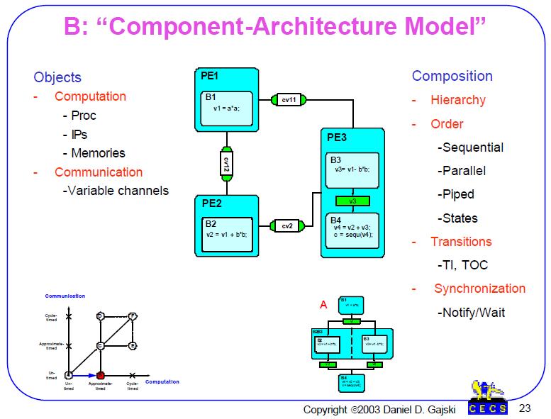
63 Component-Architecture Model has same composition rules but several new objects representing different components. Additional computation objects are Processing Elements (PEs) that include processors, IPs and memories while new communication objects are variable channels used for communication between PEs. Inside the PEs we can still use behaviors and variables since execution is sequential and running on one processor. Since each behavior has been assigned to a PE, we can easily estimate the time for execution of each behavior. On the other hand, channels have not been assigned to busses and therefore we can not estimate the communication time.
64
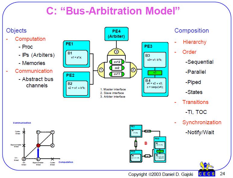
65 Bus-Arbitration Model a new component for communication is added: bus channel. Several variable channels are assigned to the bus channel. Since bus channel transfers data from a set of PEs to another set of PEs, we must insert a new arbiter PE to determine bus priority between several competing channels. Since bus has been selected we can also estimate the communication time for each channel.

66
67 Bus-Functional Model a real protocol is inserted into bus channel. Therefore, bus channel becomes cycle-accurate. The rest of the model stays the same. The communication traffic can be now accurately estimated.
68
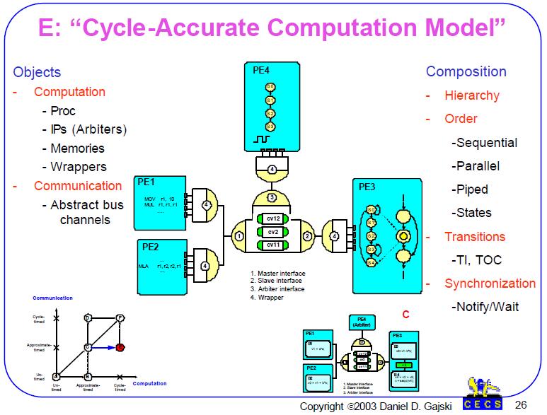
69 Cycle-Accurate Computation Model computation behaviors or processes are refined into SFSMD or FSMD models. Computation in each is therefore cycle-accurate while communication is still abstract with approximate timing. Since communication and computation do not have the same time granularity, each PE is encapsulated into a wrapper that abstracts its cycle-accurate time to approximate time of the communication model.
70
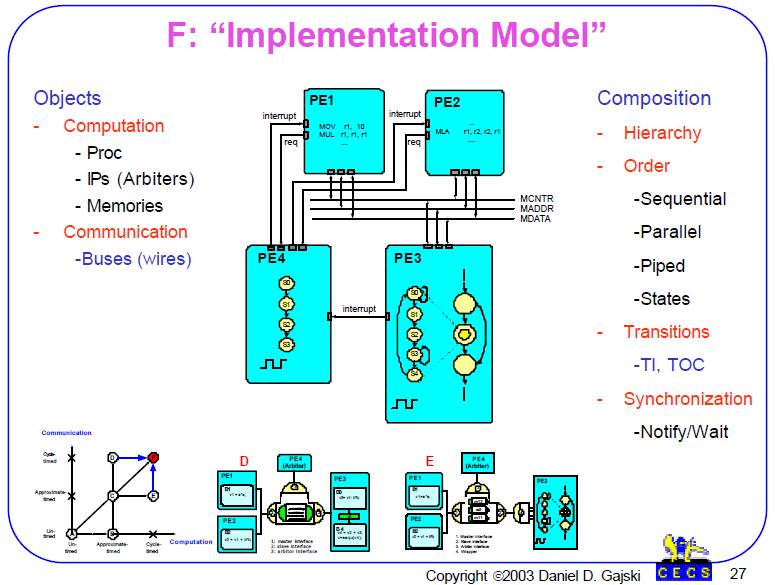
71 Cycle-Accurate Implementation Model This model has cycle-accurate time in both computation and communication. Furthermore, the abstract bus channel is replaced with bus wires, while its functionality is unlined into PEs. In addition channel functionality is converted into FSMD model and combined with computational FSMD model.
72 Model Taxonomy 1. State Oriented (state diagram) for control systems temporal behavior 2. Activity Oriented (dataflow graph) for transformational systems like digital signal processing 3. Structure Oriented (block diagram) 4. Data Oriented (entity relationship diagram) for information systems lik databases 3. Heterogeneous
73
System Level Design Flow
 System Level Design Flow What is needed and what is not Daniel D. Gajski Center for Embedded Computer Systems University of California, Irvine www.cecs.uci.edu/~gajski System Level Design Flow What is
SoC Design for the New Millennium Daniel D. Gajski
 SoC Design for the New Millennium Daniel D. Gajski Center for Embedded Computer Systems University of California, Irvine www.cecs.uci.edu/~gajski Outline System gap Design flow Model algebra System environment
SpecC Methodology for High-Level Modeling
 EDP 2002 9 th IEEE/DATC Electronic Design Processes Workshop SpecC Methodology for High-Level Modeling Rainer Dömer Daniel D. Gajski Andreas Gerstlauer Center for Embedded Computer Systems Universitiy
Unit 2: High-Level Synthesis
 Course contents Unit 2: High-Level Synthesis Hardware modeling Data flow Scheduling/allocation/assignment Reading Chapter 11 Unit 2 1 High-Level Synthesis (HLS) Hardware-description language (HDL) synthesis
Hardware Design Environments. Dr. Mahdi Abbasi Computer Engineering Department Bu-Ali Sina University
 Hardware Design Environments Dr. Mahdi Abbasi Computer Engineering Department Bu-Ali Sina University Outline Welcome to COE 405 Digital System Design Design Domains and Levels of Abstractions Synthesis
Introduction to Electronic Design Automation. Model of Computation. Model of Computation. Model of Computation
 Introduction to Electronic Design Automation Model of Computation Jie-Hong Roland Jiang 江介宏 Department of Electrical Engineering National Taiwan University Spring 03 Model of Computation In system design,
HARDWARE SOFTWARE CO-DESIGN
 HARDWARE SOFTWARE CO-DESIGN BITS Pilani Dubai Campus Dr Jagadish Nayak Models and Architecture BITS Pilani Dubai Campus Models and Architecture Model: a set of functional objects and rules for composing
ICS 252 Introduction to Computer Design
 ICS 252 Introduction to Computer Design Lecture 3 Fall 2006 Eli Bozorgzadeh Computer Science Department-UCI System Model According to Abstraction level Architectural, logic and geometrical View Behavioral,
COE 561 Digital System Design & Synthesis Introduction
 1 COE 561 Digital System Design & Synthesis Introduction Dr. Aiman H. El-Maleh Computer Engineering Department King Fahd University of Petroleum & Minerals Outline Course Topics Microelectronics Design
Hardware/Software Co-design
 Hardware/Software Co-design Zebo Peng, Department of Computer and Information Science (IDA) Linköping University Course page: http://www.ida.liu.se/~petel/codesign/ 1 of 52 Lecture 1/2: Outline : an Introduction
EE414 Embedded Systems Ch 9. State Machines
 EE414 Embedded Systems Ch 9. State Machines Byung Kook Kim School of Electrical Engineering Korea Advanced Institute of Science and Technology Outline State Machine Model 9.1 Introduction 9.2 Models vs.
Design Methodologies. Kai Huang
 Design Methodologies Kai Huang News Is that real? In such a thermally constrained environment, going quad-core only makes sense if you can properly power gate/turbo up when some cores are idle. I have
I 3 I 2. ! Language of logic design " Logic optimization, state, timing, CAD tools
 Course Wrap-up Let s Try the Priority Encoder One More Time = =! Priority Encoder Revisited! What (We Hope) You Learned I 3 O 3 I j O j! Design Methodology! I 2 O 2 I O I O Zero Oj Ij Ij CS 5 - Spring
ECE 587 Hardware/Software Co-Design Lecture 12 Verification II, System Modeling
 ECE 587 Hardware/Software Co-Design Spring 2018 1/20 ECE 587 Hardware/Software Co-Design Lecture 12 Verification II, System Modeling Professor Jia Wang Department of Electrical and Computer Engineering
Hardware Description Languages & System Description Languages Properties
 Hardware Description Languages & System Description Languages Properties There is a need for executable specification language that is capable of capturing the functionality of the system in a machine-readable
HIGH-LEVEL SYNTHESIS
 HIGH-LEVEL SYNTHESIS Page 1 HIGH-LEVEL SYNTHESIS High-level synthesis: the automatic addition of structural information to a design described by an algorithm. BEHAVIORAL D. STRUCTURAL D. Systems Algorithms
Synthesis at different abstraction levels
 Synthesis at different abstraction levels System Level Synthesis Clustering. Communication synthesis. High-Level Synthesis Resource or time constrained scheduling Resource allocation. Binding Register-Transfer
High-Level Synthesis (HLS)
") Course contents Unit 11: High-Level Synthesis Hardware modeling Data flow Scheduling/allocation/assignment Reading Chapter 11 Unit 11 1 High-Level Synthesis (HLS) Hardware-description language (HDL) synthesis
Course contents Unit 11: High-Level Synthesis Hardware modeling Data flow Scheduling/allocation/assignment Reading Chapter 11 Unit 11 1 High-Level Synthesis (HLS) Hardware-description language (HDL) synthesis
Lecture #1: Introduction
 Lecture #1: Introduction Kunle Olukotun Stanford EE183 January 8, 20023 What is EE183? EE183 is continuation of EE121 Digital Logic Design is a a minute to learn, a lifetime to master Programmable logic
MODELING LANGUAGES AND ABSTRACT MODELS. Giovanni De Micheli Stanford University. Chapter 3 in book, please read it.
 MODELING LANGUAGES AND ABSTRACT MODELS Giovanni De Micheli Stanford University Chapter 3 in book, please read it. Outline Hardware modeling issues: Representations and models. Issues in hardware languages.
Codesign Framework. Parts of this lecture are borrowed from lectures of Johan Lilius of TUCS and ASV/LL of UC Berkeley available in their web.
 Codesign Framework Parts of this lecture are borrowed from lectures of Johan Lilius of TUCS and ASV/LL of UC Berkeley available in their web. Embedded Processor Types General Purpose Expensive, requires
CS2214 COMPUTER ARCHITECTURE & ORGANIZATION SPRING 2014
 CS2214 COMPUTER ARCHITECTURE & ORGANIZATION SPRING 2014 DIGITAL SYSTEM DESIGN BASICS 1. Introduction A digital system performs microoperations. The most well known digital system example is is a microprocessor.
NISC Application and Advantages
 NISC Application and Advantages Daniel D. Gajski Mehrdad Reshadi Center for Embedded Computer Systems University of California, Irvine Irvine, CA 92697-3425, USA {gajski, reshadi}@cecs.uci.edu CECS Technical
Hardware Modeling using Verilog Prof. Indranil Sengupta Department of Computer Science and Engineering Indian Institute of Technology, Kharagpur
 Hardware Modeling using Verilog Prof. Indranil Sengupta Department of Computer Science and Engineering Indian Institute of Technology, Kharagpur Lecture 01 Introduction Welcome to the course on Hardware
Architectural-Level Synthesis. Giovanni De Micheli Integrated Systems Centre EPF Lausanne
 Architectural-Level Synthesis Giovanni De Micheli Integrated Systems Centre EPF Lausanne This presentation can be used for non-commercial purposes as long as this note and the copyright footers are not
Two HDLs used today VHDL. Why VHDL? Introduction to Structured VLSI Design
 Two HDLs used today Introduction to Structured VLSI Design VHDL I VHDL and Verilog Syntax and ``appearance'' of the two languages are very different Capabilities and scopes are quite similar Both are industrial
Register Transfer Level in Verilog: Part I
 Source: M. Morris Mano and Michael D. Ciletti, Digital Design, 4rd Edition, 2007, Prentice Hall. Register Transfer Level in Verilog: Part I Lan-Da Van ( 范倫達 ), Ph. D. Department of Computer Science National
Cycle-accurate RTL Modeling with Multi-Cycled and Pipelined Components
 Cycle-accurate RTL Modeling with Multi-Cycled and Pipelined Components Rainer Dömer, Andreas Gerstlauer, Dongwan Shin Technical Report CECS-04-19 July 22, 2004 Center for Embedded Computer Systems University
Embedded System Design
 Modeling, Synthesis, Verification Daniel D. Gajski, Samar Abdi, Andreas Gerstlauer, Gunar Schirner 9/29/2011 Outline System design trends Model-based synthesis Transaction level model generation Application
ESE Back End 2.0. D. Gajski, S. Abdi. (with contributions from H. Cho, D. Shin, A. Gerstlauer)
") ESE Back End 2.0 D. Gajski, S. Abdi (with contributions from H. Cho, D. Shin, A. Gerstlauer) Center for Embedded Computer Systems University of California, Irvine http://www.cecs.uci.edu 1 Technology advantages
ESE Back End 2.0 D. Gajski, S. Abdi (with contributions from H. Cho, D. Shin, A. Gerstlauer) Center for Embedded Computer Systems University of California, Irvine http://www.cecs.uci.edu 1 Technology advantages
VHDL for Synthesis. Course Description. Course Duration. Goals
 VHDL for Synthesis Course Description This course provides all necessary theoretical and practical know how to write an efficient synthesizable HDL code through VHDL standard language. The course goes
INSTITUTE OF AERONAUTICAL ENGINEERING Dundigal, Hyderabad ELECTRONICS AND COMMUNICATIONS ENGINEERING
 INSTITUTE OF AERONAUTICAL ENGINEERING Dundigal, Hyderabad - 00 0 ELECTRONICS AND COMMUNICATIONS ENGINEERING QUESTION BANK Course Name : DIGITAL DESIGN USING VERILOG HDL Course Code : A00 Class : II - B.
Stacked FSMD: A New Microarchitecture Model for High-Level Synthesis. Khushwinder Singh Jasrotia
 Stacked FSMD: A New Microarchitecture Model for High-Level Synthesis by Khushwinder Singh Jasrotia A thesis submitted in conformity with the requirements for the Degree of Master of Applied Science in
Verilog. What is Verilog? VHDL vs. Verilog. Hardware description language: Two major languages. Many EDA tools support HDL-based design
 Verilog What is Verilog? Hardware description language: Are used to describe digital system in text form Used for modeling, simulation, design Two major languages Verilog (IEEE 1364), latest version is
Hardware Description Languages & System Description Languages Properties
 Hardware Description Languages & System Description Languages Properties There is a need for executable specification language that is capable of capturing the functionality of the system in a machine-readable
Block diagram view. Datapath = functional units + registers
 Computer design an application of digital logic design procedures Computer = processing unit + memory system Processing unit = control + datapath Control = finite state machine inputs = machine instruction,
VHDL. VHDL History. Why VHDL? Introduction to Structured VLSI Design. Very High Speed Integrated Circuit (VHSIC) Hardware Description Language
 Hardware Description Language") VHDL Introduction to Structured VLSI Design VHDL I Very High Speed Integrated Circuit (VHSIC) Hardware Description Language Joachim Rodrigues A Technology Independent, Standard Hardware description Language
VHDL Introduction to Structured VLSI Design VHDL I Very High Speed Integrated Circuit (VHSIC) Hardware Description Language Joachim Rodrigues A Technology Independent, Standard Hardware description Language
EECS150 - Digital Design Lecture 5 - Verilog Logic Synthesis
 EECS150 - Digital Design Lecture 5 - Verilog Logic Synthesis Jan 31, 2012 John Wawrzynek Spring 2012 EECS150 - Lec05-verilog_synth Page 1 Outline Quick review of essentials of state elements Finite State
MLR Institute of Technology
 MLR Institute of Technology Laxma Reddy Avenue, Dundigal, Quthbullapur (M), Hyderabad 500 043 Course Name Course Code Class Branch ELECTRONICS AND COMMUNICATIONS ENGINEERING QUESTION BANK : DIGITAL DESIGN
Transaction-Level Modeling Definitions and Approximations. 2. Definitions of Transaction-Level Modeling
 Transaction-Level Modeling Definitions and Approximations EE290A Final Report Trevor Meyerowitz May 20, 2005 1. Introduction Over the years the field of electronic design automation has enabled gigantic
Cadence SystemC Design and Verification. NMI FPGA Network Meeting Jan 21, 2015
 Cadence SystemC Design and Verification NMI FPGA Network Meeting Jan 21, 2015 The High Level Synthesis Opportunity Raising Abstraction Improves Design & Verification Optimizes Power, Area and Timing for
Outline. SLD challenges Platform Based Design (PBD) Leveraging state of the art CAD Metropolis. Case study: Wireless Sensor Network
 Leveraging state of the art CAD Metropolis. Case study: Wireless Sensor Network") By Alberto Puggelli Outline SLD challenges Platform Based Design (PBD) Case study: Wireless Sensor Network Leveraging state of the art CAD Metropolis Case study: JPEG Encoder SLD Challenge Establish a
By Alberto Puggelli Outline SLD challenges Platform Based Design (PBD) Case study: Wireless Sensor Network Leveraging state of the art CAD Metropolis Case study: JPEG Encoder SLD Challenge Establish a
Control and Datapath 8
 Control and Datapath 8 Engineering attempts to develop design methods that break a problem up into separate steps to simplify the design and increase the likelihood of a correct solution. Digital system
Energy Estimation Based on Hierarchical Bus Models for Power-Aware Smart Cards
 Energy Estimation Based on Hierarchical Bus Models for Power-Aware Smart Cards U. Neffe, K. Rothbart, Ch. Steger, R. Weiss Graz University of Technology Inffeldgasse 16/1 8010 Graz, AUSTRIA {neffe, rothbart,
System-level simulation (HW/SW co-simulation) Outline. EE290A: Design of Embedded System ASV/LL 9/10
 Outline. EE290A: Design of Embedded System ASV/LL 9/10") System-level simulation (/SW co-simulation) Outline Problem statement Simulation and embedded system design functional simulation performance simulation POLIS implementation partitioning example implementation
System-level simulation (/SW co-simulation) Outline Problem statement Simulation and embedded system design functional simulation performance simulation POLIS implementation partitioning example implementation
CHAPTER - 2 : DESIGN OF ARITHMETIC CIRCUITS
 Contents i SYLLABUS osmania university UNIT - I CHAPTER - 1 : BASIC VERILOG HDL Introduction to HDLs, Overview of Digital Design With Verilog HDL, Basic Concepts, Data Types, System Tasks and Compiler
Lecture 6B Hierarchical/Concurrent State Machine Models (HCFSM)
") ECE 474A/57A Computer-Aided Logic Design Outline Models vs. Languages Lecture 6B Hierarchical/Concurrent State Machine Models (HCFSM) State Machine Model FSM/FSMD HCFSM and Statecharts Language Program-State
ECE 474A/57A Computer-Aided Logic Design Outline Models vs. Languages Lecture 6B Hierarchical/Concurrent State Machine Models (HCFSM) State Machine Model FSM/FSMD HCFSM and Statecharts Language Program-State
HDL. Operations and dependencies. FSMs Logic functions HDL. Interconnected logic blocks HDL BEHAVIORAL VIEW LOGIC LEVEL ARCHITECTURAL LEVEL
 ARCHITECTURAL-LEVEL SYNTHESIS Motivation. Outline cgiovanni De Micheli Stanford University Compiling language models into abstract models. Behavioral-level optimization and program-level transformations.
VHDL: RTL Synthesis Basics. 1 of 59
 VHDL: RTL Synthesis Basics 1 of 59 Goals To learn the basics of RTL synthesis. To be able to synthesize a digital system, given its VHDL model. To be able to relate VHDL code to its synthesized output.
Register Transfer Methodology II
 Register Transfer Methodology II Chapter 12 1 Outline 1. Design example: One shot pulse generator 2. Design Example: GCD 3. Design Example: UART 4. Design Example: SRAM Interface Controller 5. Square root
Outline. Register Transfer Methodology II. 1. One shot pulse generator. Refined block diagram of FSMD
 Outline Register Transfer Methodology II 1. Design example: One shot pulse generator 2. Design Example: GCD 3. Design Example: UART 4. Design Example: SRAM Interface Controller 5. Square root approximation
EE595. Part VIII Overall Concept on VHDL. EE 595 EDA / ASIC Design Lab
 EE595 Part VIII Overall Concept on VHDL VHDL is a Standard Language Standard in the electronic design community. VHDL will virtually guarantee that you will not have to throw away and re-capture design
3 Designing Digital Systems with Algorithmic State Machine Charts
 3 Designing with Algorithmic State Machine Charts An ASM chart is a method of describing the sequential operations of a digital system which has to implement an algorithm. An algorithm is a well defined
FPGA for Software Engineers
 FPGA for Software Engineers Course Description This course closes the gap between hardware and software engineers by providing the software engineer all the necessary FPGA concepts and terms. The course
Digital System Design
 Digital System Design Analog time varying signals that can take on any value across a continuous range of voltage, current or other metric Digital signals are modeled with two states, 0 or 1 underneath
Chapter 8: Computation models 8-1
 Chapter 8: Computation models 8-1 Chapter 8 Computation models 8.1 Introduction We implement a system s processing behavior with processors. But to accomplish this, we must have first described that processing
HW/SW Co-design. Design of Embedded Systems Jaap Hofstede Version 3, September 1999
 HW/SW Co-design Design of Embedded Systems Jaap Hofstede Version 3, September 1999 Embedded system Embedded Systems is a computer system (combination of hardware and software) is part of a larger system
CS 310 Embedded Computer Systems DESIGN
 1 EMBEDDED SYSTEM DESIGN Embedded System Design 2 3 Specification Introduction 4 Describing embedded d system s processing behavior Can be extremely difficult Complexity increasing with increasing IC capacity
Contemporary Design. Traditional Hardware Design. Traditional Hardware Design. HDL Based Hardware Design User Inputs. Requirements.
 Contemporary Design We have been talking about design process Let s now take next steps into examining in some detail Increasing complexities of contemporary systems Demand the use of increasingly powerful
SPECC: SPECIFICATION LANGUAGE AND METHODOLOGY
 SPECC: SPECIFICATION LANGUAGE AND METHODOLOGY SPECC: SPECIFICATION LANGUAGE AND METHODOLOGY Daniel D. Gajski Jianwen Zhu Rainer Dömer Andreas Gerstlauer Shuqing Zhao University of California, Irvine SPRINGER
Datapath Allocation. Zoltan Baruch. Computer Science Department, Technical University of Cluj-Napoca
 Datapath Allocation Zoltan Baruch Computer Science Department, Technical University of Cluj-Napoca e-mail: baruch@utcluj.ro Abstract. The datapath allocation is one of the basic operations executed in
Model-Based Design for effective HW/SW Co-Design Alexander Schreiber Senior Application Engineer MathWorks, Germany
 Model-Based Design for effective HW/SW Co-Design Alexander Schreiber Senior Application Engineer MathWorks, Germany 2013 The MathWorks, Inc. 1 Agenda Model-Based Design of embedded Systems Software Implementation
System Synthesis of Digital Systems
 System Synthesis Introduction 1 System Synthesis of Digital Systems Petru Eles, Zebo Peng System Synthesis Introduction 2 Literature: Introduction P. Eles, K. Kuchcinski and Z. Peng "System Synthesis with
Word-Level Equivalence Checking in Bit-Level Accuracy by Synthesizing Designs onto Identical Datapath
 972 PAPER Special Section on Formal Approach Word-Level Equivalence Checking in Bit-Level Accuracy by Synthesizing Designs onto Identical Datapath Tasuku NISHIHARA a), Member, Takeshi MATSUMOTO, and Masahiro
VHDL simulation and synthesis
 VHDL simulation and synthesis How we treat VHDL in this course You will not become an expert in VHDL after taking this course The goal is that you should learn how VHDL can be used for simulation and synthesis
Sunburst Design - Verilog-2001 Design & Best Coding Practices by Recognized Verilog & SystemVerilog Guru, Cliff Cummings of Sunburst Design, Inc.
 World Class Verilog & SystemVerilog Training Sunburst Design - Verilog-2001 Design & Best Coding Practices by Recognized Verilog & SystemVerilog Guru, Cliff Cummings of Sunburst Design, Inc. Cliff Cummings
EE 3170 Microcontroller Applications
 EE 3170 Microcontroller Applications Lecture 4 : Processors, Computers, and Controllers - 1.2 (reading assignment), 1.3-1.5 Based on slides for ECE3170 by Profs. Kieckhafer, Davis, Tan, and Cischke Outline
Outline. CPE/EE 422/522 Advanced Logic Design L05. Review: General Model of Moore Sequential Machine. Review: Mealy Sequential Networks.
 Outline CPE/EE 422/522 Advanced Logic Design L05 Electrical and Computer Engineering University of Alabama in Huntsville What we know Combinational Networks Sequential Networks: Basic Building Blocks,
ESL design with the Agility Compiler for SystemC
 ESL design with the Agility Compiler for SystemC SystemC behavioral design & synthesis Steve Chappell & Chris Sullivan Celoxica ESL design portfolio Complete ESL design environment Streaming Video Processing
Register Transfer Level
 Register Transfer Level Something between the logic level and the architecture level A convenient way to describe synchronous sequential systems State diagrams for pros Hierarchy of Designs The design
Embedded System Design Modeling, Synthesis, Verification
 Modeling, Synthesis, Verification Daniel D. Gajski, Samar Abdi, Andreas Gerstlauer, Gunar Schirner Chapter 4: System Synthesis Outline System design trends Model-based synthesis Transaction level model
Computer Organization. Structure of a Computer. Registers. Register Transfer. Register Files. Memories
 Computer Organization Structure of a Computer Computer design as an application of digital logic design procedures Computer = processing unit + memory system Processing unit = control + Control = finite
EE382V: System-on-a-Chip (SoC) Design
 Design") EE382V: System-on-a-Chip (SoC) Design Lecture 8 HW/SW Co-Design Sources: Prof. Margarida Jacome, UT Austin Andreas Gerstlauer Electrical and Computer Engineering University of Texas at Austin gerstl@ece.utexas.edu
EE382V: System-on-a-Chip (SoC) Design Lecture 8 HW/SW Co-Design Sources: Prof. Margarida Jacome, UT Austin Andreas Gerstlauer Electrical and Computer Engineering University of Texas at Austin gerstl@ece.utexas.edu
Lecture 2 Hardware Description Language (HDL): VHSIC HDL (VHDL)
: VHSIC HDL (VHDL)") Lecture 2 Hardware Description Language (HDL): VHSIC HDL (VHDL) Pinit Kumhom VLSI Laboratory Dept. of Electronic and Telecommunication Engineering (KMUTT) Faculty of Engineering King Mongkut s University
Lecture 2 Hardware Description Language (HDL): VHSIC HDL (VHDL) Pinit Kumhom VLSI Laboratory Dept. of Electronic and Telecommunication Engineering (KMUTT) Faculty of Engineering King Mongkut s University
Synthesis of Combinational and Sequential Circuits with Verilog
 Synthesis of Combinational and Sequential Circuits with Verilog What is Verilog? Hardware description language: Are used to describe digital system in text form Used for modeling, simulation, design Two
EE 466/586 VLSI Design. Partha Pande School of EECS Washington State University
 EE 466/586 VLSI Design Partha Pande School of EECS Washington State University pande@eecs.wsu.edu Lecture 18 Implementation Methods The Design Productivity Challenge Logic Transistors per Chip (K) 10,000,000.10m
RTL Design (Using ASM/SM Chart)
") Digital Circuit Design and Language RTL Design (Using ASM/SM Chart) Chang, Ik Joon Kyunghee University Process of Logic Simulation and Synthesis Design Entry HDL Description Logic Simulation Functional
Digital Circuit Design and Language RTL Design (Using ASM/SM Chart) Chang, Ik Joon Kyunghee University Process of Logic Simulation and Synthesis Design Entry HDL Description Logic Simulation Functional
Scheduling in RTL Design Methodology
 cheduling in RTL Design Methodology Dongwan hin and Daniel Gajski Technical Report IC-01-65 July 1, 2001 Center for Embedded Computer ystems Information and Computer cience University of California, Irvine
An introduction to CoCentric
 A Hand-Out 1 An introduction to CoCentric Las Palmas de G. C., Spain Jun, 27 th, 2002 Agenda 2 System-level SoC design What is SystemC? CoCentric System Studio SystemC based designs verification CoCentric
(ii) Simplify and implement the following SOP function using NOR gates:
 Simplify and implement the following SOP function using NOR gates:") DHANALAKSHMI COLLEGE OF ENGINEERING DEPARTMENT OF ELECTRONICS AND COMMUNICATION ENGINEERING EE6301 DIGITAL LOGIC CIRCUITS UNIT I NUMBER SYSTEMS AND DIGITAL LOGIC FAMILIES PART A 1. How can an OR gate be
DHANALAKSHMI COLLEGE OF ENGINEERING DEPARTMENT OF ELECTRONICS AND COMMUNICATION ENGINEERING EE6301 DIGITAL LOGIC CIRCUITS UNIT I NUMBER SYSTEMS AND DIGITAL LOGIC FAMILIES PART A 1. How can an OR gate be
Abstraction Layers for Hardware Design
 SYSTEMC Slide -1 - Abstraction Layers for Hardware Design TRANSACTION-LEVEL MODELS (TLM) TLMs have a common feature: they implement communication among processes via function calls! Slide -2 - Abstraction
A Process Model suitable for defining and programming MpSoCs
 A Process Model suitable for defining and programming MpSoCs MpSoC-Workshop at Rheinfels, 29-30.6.2010 F. Mayer-Lindenberg, TU Hamburg-Harburg 1. Motivation 2. The Process Model 3. Mapping to MpSoC 4.
RTL Power Estimation and Optimization
 Power Modeling Issues RTL Power Estimation and Optimization Model granularity Model parameters Model semantics Model storage Model construction Politecnico di Torino Dip. di Automatica e Informatica RTL
Modeling and Simulation of System-on. Platorms. Politecnico di Milano. Donatella Sciuto. Piazza Leonardo da Vinci 32, 20131, Milano
 Modeling and Simulation of System-on on-chip Platorms Donatella Sciuto 10/01/2007 Politecnico di Milano Dipartimento di Elettronica e Informazione Piazza Leonardo da Vinci 32, 20131, Milano Key SoC Market
ECE 587 Hardware/Software Co-Design Lecture 23 Hardware Synthesis III
 ECE 587 Hardware/Software Co-Design Spring 2018 1/28 ECE 587 Hardware/Software Co-Design Lecture 23 Hardware Synthesis III Professor Jia Wang Department of Electrical and Computer Engineering Illinois
Overview of Digital Design Methodologies
 Overview of Digital Design Methodologies ELEC 5402 Pavan Gunupudi Dept. of Electronics, Carleton University January 5, 2012 1 / 13 Introduction 2 / 13 Introduction Driving Areas: Smart phones, mobile devices,
EECS Components and Design Techniques for Digital Systems. Lec 20 RTL Design Optimization 11/6/2007
 EECS 5 - Components and Design Techniques for Digital Systems Lec 2 RTL Design Optimization /6/27 Shauki Elassaad Electrical Engineering and Computer Sciences University of California, Berkeley Slides
08 - Address Generator Unit (AGU)
") October 2, 2014 Todays lecture Memory subsystem Address Generator Unit (AGU) Schedule change A new lecture has been entered into the schedule (to compensate for the lost lecture last week) Memory subsystem
October 2, 2014 Todays lecture Memory subsystem Address Generator Unit (AGU) Schedule change A new lecture has been entered into the schedule (to compensate for the lost lecture last week) Memory subsystem
The SpecC System-Level Design Language and Methodology, Part 1. Class 309
 Embedded Systems Conference San Francisco 2002 The SpecC System-Level Design Language and Methodology, Part 1 Class 309 Rainer Dömer Center for Embedded Computer Systems Universitiy of California, Irvine,
HIERARCHICAL DESIGN. RTL Hardware Design by P. Chu. Chapter 13 1
 HIERARCHICAL DESIGN Chapter 13 1 Outline 1. Introduction 2. Components 3. Generics 4. Configuration 5. Other supporting constructs Chapter 13 2 1. Introduction How to deal with 1M gates or more? Hierarchical
Outline HIERARCHICAL DESIGN. 1. Introduction. Benefits of hierarchical design
 Outline HIERARCHICAL DESIGN 1. Introduction 2. Components 3. Generics 4. Configuration 5. Other supporting constructs Chapter 13 1 Chapter 13 2 1. Introduction How to deal with 1M gates or more? Hierarchical
Programmable Logic Devices II
 São José February 2015 Prof. Hoeller, Prof. Moecke (http://www.sj.ifsc.edu.br) 1 / 28 Lecture 01: Complexity Management and the Design of Complex Digital Systems Prof. Arliones Hoeller arliones.hoeller@ifsc.edu.br
Embedded System Design
 Modeling, Synthesis, Verification Daniel D. Gajski, Samar Abdi, Andreas Gerstlauer, Gunar Schirner 7/8/2009 Modeling Abstract view of a design Representation of reality in each design step Apply analysis,
Specifications Part 1
 pm3 12 Specifications Part 1 Embedded System Design Kluwer Academic Publisher by Peter Marwedel TU Dortmund 2008/11/15 ine Marwedel, 2003 Graphics: Alexandra Nolte, Ges Introduction 12, 2008-2 - 1 Specification
Embedded Systems Dr. Santanu Chaudhury Department of Electrical Engineering Indian Institution of Technology, Delhi
 Embedded Systems Dr. Santanu Chaudhury Department of Electrical Engineering Indian Institution of Technology, Delhi Lecture - 34 Compilers for Embedded Systems Today, we shall look at the compilers, which
The S6000 Family of Processors
 The S6000 Family of Processors Today s Design Challenges The advent of software configurable processors In recent years, the widespread adoption of digital technologies has revolutionized the way in which
Overview of Digital Design with Verilog HDL 1
 Overview of Digital Design with Verilog HDL 1 1.1 Evolution of Computer-Aided Digital Design Digital circuit design has evolved rapidly over the last 25 years. The earliest digital circuits were designed
ARM 64-bit Register File
 ARM 64-bit Register File Introduction: In this class we will develop and simulate a simple, pipelined ARM microprocessor. Labs #1 & #2 build some basic components of the processor, then labs #3 and #4
Computer Organization
 Computer Organization! Computer design as an application of digital logic design procedures! Computer = processing unit + memory system! Processing unit = control + datapath! Control = finite state machine
Verilog for High Performance
 Verilog for High Performance Course Description This course provides all necessary theoretical and practical know-how to write synthesizable HDL code through Verilog standard language. The course goes