Design Methodologies. Kai Huang
|
|
|
- Karen Richardson
- 5 years ago
- Views:
Transcription


1 Design Methodologies Kai Huang
 do this properly, so until we hit that point the optimal target is likely two cores. http://gizmodo.")
2 News Is that real? In such a thermally constrained environment, going quad-core only makes sense if you can properly power gate/turbo up when some cores are idle. I have yet to see any mobile SoC vendor (with the exception of Intel with Bay Trail) do this properly, so until we hit that point the optimal target is likely two cores. 12/18/2013 Kai.Huang@tum 2
3 Outline Design Trend Recap Gajski s Y-Chart Kienhuis Y-Chart Model-based Design 12/18/2013 Kai.Huang@tum 3
4 Embedded Systems Design Embedded Systems Design is NOT just a special case of either hardware (Computer/Electrical Engineering) or software (Software Engineering/Computer Science) design. It has functional requirements (expected services), and it has non-functional requirements /constraints o Interaction constraints: deadlines, throughput, jitter o Execution constraints: available resources, power, failure rates Embedded Systems design discipline needs to combine o Computer Science o Computer/Electrical Engineering 12/18/2013 Kai.Huang@tum 4
5 Trends in Embedded Systems Higher Degree of Integration o Moore s law Power wall o Towards Multi-Processor (System-on-Chip) Software Increasing o Flexibility and time-to-market 12/18/2013 Kai.Huang@tum 5

6 Power Wall Law of Physics: All electrical power consumed is eventually radiated as heat Reasoning: use multiple cores with lower frequency to obtain the same overall performance 12/18/2013 6
7 Power Wall for MPSoC Reasoning: packing more transistors needs deeper sub micro CMOS techniques which results in larger leakage current 12/18/2013 7

8 Embedded Software Complexity Software engineers always push the limits of the hardware capability IEEE Computer 2009 special issue on Embedded Software 12/18/2013 8

9 Telecom Example Software defined radio 12/18/2013 9


10 Complexity (HW/SW) iphone iphone ARM MHz 128MB Frequency: 620MHz 1.3GHz Memory: 128MB 1GB Transistors:? 1B+ iphone 3G ARM MHz 128MB iphone 4 Coretex A8 iphone 3GS 1 GHz ARM CortexA8 833 MHz 256 MB iphone 4S Dual-core A9 SoC 1GHz iphone 5 ARMv7s 1.3GHz iphone 5S/C ARMv8-A 1.3 GHz 1GB, 1B+ transistors Data from: 12/18/2013 Kai.Huang@tum 10
11 Log Scale Design Crisis: Design Productivity Gap Gates/cm 2 Moore s Law (59% CAGR) Design Productivity (20-25% CAGR) Widening Gap Trigger Paradigm Shift! Software Productivity (8-10% CAGR) 0.35µ 0.25µ 0.18µ 0.15µ 0.12µ 0.1µ Technology (micron) The well-know productivity gap generated by the disparity between the rapid paces the design complexity increased in comparison to that of design productivity 12/18/2013 Kai.Huang@tum 11 CAGR: Compound Annual Growth Rate
12 Needs of New Methodology Kurt Keutzer, et. al. System-Level Design: Orthogonalization of Concerns and Platform-Based Design," IEEE TCAD, 19(12), December we believe that the lack of appropriate methodology and tool support for modeling of concurrency in its various forms is an essential limiting factor in the use of both RTL and commonly used programming languages to express design complexity 12/18/
13 System Design: Gajski Y-Chart Three design views o Behavior (specification/functionality) o Structure (netlist/block diagram) o Physical (layout/board design) Four abstraction levels o Circuit level o Logic level o Processor (RTL) level o System level Four component libraries o Transistors o Logic (standard cells) o RTL (ALUs, RFs,...) o Processor/Communication (standard, custom) Behavioral System model Processor model Boolean equations Transfer functions System Level Processor Level Logic Level Circuit Level Rectangles Cell, Module Plans Floor Plans PCB Structural Processor, bus, ALU, Register file,.. Gate,Flip-Flops Transistors Physical/Geometry 12/18/2013 Kai.Huang@tum 13

")


14 Printed Circuit Board (PCB) 12/18/

 12/18/2013 Kai.")
15 Floorplan In electronic design automation, a floorplan of an integrated circuit is a schematic representation of tentative placement of its major functional blocks. Intel Lynnfield (Core i5/i7) 12/18/2013 Kai.Huang@tum 15

16 Standard Cell A standard cell is a group of transistor and interconnect structures that provides a Boolean logic function or a storage function IIT/OSU standard cell library 2-XOR gate in 0.18µm technology 12/18/2013 Kai.Huang@tum 16
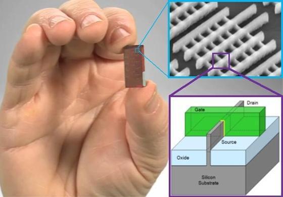
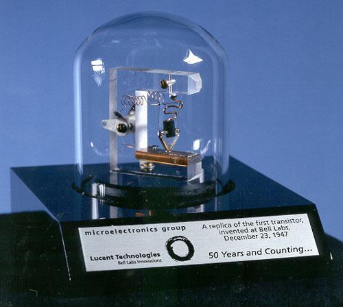
17 Transistors 12/18/

18 Logic Gate Flip-Flop (SR NOR latch) where S and R stand for set and reset 12/18/2013 Kai.Huang@tum 18
19 Processor Structure Model 12/18/
20 System Model Behavior (MoC) Structure (TLM) 12/18/ /18/
21 Synthesis Definition: The process of converting the given behavior into a structure on an abstraction level Behavioral System Level Processor Level Logic Level Structural Synthesis can be performed at every level of abstraction System model Processor model Boolean equations Transfer functions Circuit Level Rectangles Cell, Module Plans Processor, bus, ALU, Register file,.. Gate,Flip-Flops Transistors Examples: o Processor Level Synthesis o System Level Synthesis Floor Plans PCB Physical/Geometry 12/18/2013 Kai.Huang@tum 21
22 Processor Level Synthesis Processor model o o o FSM with Datapath CDFG Instruction set flow chart Processor structure model o o o Datapath components Storage (registers, RFs, Scratch pads, data memories) Functional units (ALUs, multipliers, shifters, special functions) Connection (buses, selectors, bridges) Controller components Registers (PC, Status register, Control word or Instruction register) Others (AG, Control memory or Program memory) Processor structure Pipelining, chaining, multi-cycling, forwarding Synthesis consists of several tasks: many different sequences possible o o Floor Plans Different models, different libraries, different features, different structures Different tools, different metrics, different quality 12/18/2013 Kai.Huang@tum 22
23 System Level Synthesis System behavior model o Use a MoC o Many MoCs exist System structural model o Set of computational components Processors IPs Custom HW components Memories o Set of communication components Buses, bridges, arbiters NoCs PCB Synthesis consists of several tasks: different sequences possible o Different MoCs, different libraries, different features, different platforms o Different tools, different metrics, different quality 12/18/2013 Kai.Huang@tum 23
24 Design methodologies Design methodology is a sequence of design models, components and tools used to design the product Methodologies evolve with technology, complexity, and automation A methodology depends on application, company and design group focus Standardization arrives when the cost of being special is too high Design Methodologies have been drastically changing with the increase in system complexity over the past half-century 12/18/2013 Kai.Huang@tum 24
25 Bottom-up Methodology Starts from the bottom level Each level generates library for the next higher level o Circuit: Standard cells for logic level o Logic: RTL components for processor level o Processor: Processing and communication components for system level o System: Embedded systems platforms for different applications Floorplaning and layout on each level 12/18/2013 Kai.Huang@tum 25
26 Bottom-up Methodology Pros o Abstraction levels clearly separated with its own library o Accurate metric estimation with layout on each level o Globally distributed development possible o Easy management Cons o An optimal library for each design is difficult to predict All possible components with all possible parameters All possible optimizations for all possible metrics o Library customization is outside the design group o Layout is performed on every level 12/18/2013 Kai.Huang@tum 26
27 Top-down Methodology Starts with the top level Functional description is converted into component netlist on each level Each component function is decomposed further on the next abstraction level Layout is given only for transistor components 12/18/
28 Top-down Methodology Pros o Highest level of customization possible on each abstraction level o Only one small transistor library needed o Only one layout design at the end Cons o Difficult metric estimation on upper levels since layout is not known until the end o Design decision impact on higher level not clear o Hot spot removal is difficult o Metric annotation (closure) from lower to higher levels needed during design iterations 12/18/2013 Kai.Huang@tum 28
29 Meet-in-the-Middle Methodology (Option 1) Combines top-down and bottom-up o Synthesis vs. layout compromise Processor level is where they meet MoC is synthesized into processor components Processor components are synthesized with RTL library System layout is generated with RTL components 12/18/2013 Kai.Huang@tum 29
30 Meet-in-the-Middle Methodology (Option 2) RTL level where they meet MoC is synthesized with processor components Processor components are synthesized with RTL library RTL components are synthesized with standard cells System layout is performed with standard cells Two levels of layout 12/18/
31 Meet-in-the-Middle Methodology Pros o Shorter synthesis o Less layout o Less libraries o Better metric closure Cons o Still needs libraries o More then one layout o Metric closure still needed o Library components may not be optimal 12/18/2013 Kai.Huang@tum 31
32 Platform Methodology System platform with standard components and synthesizable custom components for application optimization Layout is on system level or predefined with special area for custom components layout Custom components synthesized with RTL and logic and laid out with standard cells Custom components must fit into platform structure 12/18/
33 Platform Methodology Pros o Two types of layout: system layout for platform (could be predefined) and standard cell layout for custom components o Standard processors are available o Custom and interface components are added for optimization Cons o Platform customization is still needed o SW and IF components synthesis required 12/18/2013 Kai.Huang@tum 33
34 System Methodology Methodology for embedded systems developers (ASIC) System platform with architecture cells Layout on system level with architecture cells Architecture cells defined for specific application and design metrics Architecture cells pre-synthesized with RTL and logic and laid out with standard cells A retargetable compiler for architecture cells 12/18/2013 Kai.Huang@tum 34
35 System Methodology Pros o Processor-level component only o Single retargetable compiler for all architecture cells o Processor-level layout o Methodology for application experts o Minimal knowledge of system and processor levels Cons o Architecture cell definition and library o IS definition o Change of mind 12/18/2013 Kai.Huang@tum 35
36 FPGA Methodology Starts with system structure Processor components synthesized with RTL and logic components Components implemented with LUT and BRAMs Layout only once Metric estimation very difficult Estimation is hidden in the FPGA supplier tools 12/18/
37 Design Flows (Gajski s view) Three generic evolutionary design flows o Capture-and-Simulate (1960s to 1980s) Designers do the complete design manually, no automation Designers validate the design through simulation at the end of the design o Describe-and-Synthesize (late 1980s to late 1990s) Designers describe just functionality, tools synthesize structure Simulation before and after the synthesis o Specify-Explore-Refine (early 2000 to present) System design performed at several levels of abstraction At each level of abstraction designers: First, specify/model the system under design Then, explore alternative design decisions Finally, refine the model according to their decisions (i.e., put more details) The refined model is used as a specification for the next lower level 12/18/2013 Kai.Huang@tum 37

38 Traditional System Design Hardware first approach o Platform is defined by architect or based on legacy o Designers develop and verify RTL model of platform o Slow error prone process SW development after HW is finalized o Debugging is complicated on the board due to limited observablity o HW errors found during SW development are difficult to rectify Application is ported after system SW is finalized 12/18/2013 Kai.Huang@tum 38

39 Virtual Platform based System Design Virtual platform (VP) is a fast model of the HW platform o Typically an instruction set simulator or C/C++ model of the processor o Peripherals are modeled as remotely callable functions o Executes several orders of magnitude faster than RTL SW and HW development are concurrent o VP serves as the golden model for both SW and HW development o SW development can start earlier o HW designers can use SW for realistic test bench for RTL 12/18/2013 Kai.Huang@tum 39
40 Model-based System Design Model based design gives control to application developers o Application is captured as high level C/C++/UML specification o Transaction level model (TLM) is used to verify and evaluate the design System synthesis o The best platform for given application can be synthesized automatically o For legacy platforms, application mapping can be generated automatically o Cycle accurate SW/HW can be generated from TLM for implementation 12/18/2013 Kai.Huang@tum 40
41 Modeling, Design, Analysis Modeling is the process of gaining a deeper understanding of a system through imitation. Models specify what a system does. Design is the structured creation of artifacts. It specifies how a system does what it does. This includes optimization. Analysis is the process of gaining a deeper understanding of a system through dissection. It specifies why a system does what it does (or fails to do what a model says it should do). 12/18/2013 Kai.Huang@tum 41
42 What for Modeling? Developing insight about a system, process, or artifact through imitation. A model is the artifact that imitates the system, process, or artifact of interest. A mathematical model is model in the form of a set of definitions and mathematical formulas/objects. 12/18/2013 Kai.Huang@tum 42
43 What is Model-Based Design? Create a mathematical model of all the parts of the embedded system o Physical world o Control system o Software environment o Hardware platform o Network o Sensors and actuators Different sub-systems, different approaches to modeling Construct the implementation from the model o Goal: automate this construction, like a compiler o In practice, only portions are automatically constructed 12/18/2013 Kai.Huang@tum 43
44 The Other Y-Chart [Kienhuis et al.] What it does How it does Architecture model Mapping Applications model Performance Evaluation Use different mapping strategies Suggest architectural improvements Performance Numbers Rewrite the applications Three different ways to improve the performance of a system 12/18/2013 Kai.Huang@tum 44
45 The Other Y-Chart Separation of Concerns o Application vs. architecture modeling Different to Gajski Y-Chart o Gajski Y-Chart: covers mainly the synthesis aspect o Kienhuis Y-Chart: covers mainly the quality assessment aspect 12/18/2013 Kai.Huang@tum 45
46 Modeling and evaluation effort & accuracy Design opportunities Level of abstraction Y-Chart Design BUT at Which Level of Abstraction? Abstracting means forgetting Specification Low High High Alternative realization/design space 12/18/ Low
47 Stack of Y-Chart Estimation Models Mapping Applications Applications Applications Specify and explore at different abstract levels Matlab/ Mathematica Cycle Acc. Models Mapping Applications Applications Applications Performance Numbers Cycle Acc. Simulator move down into lower abstraction Move Down levels into Lower Abstractions (keep the concept of separation of concerns) Performance Numbers VHDL Models Mapping VHDL Simulator Applications Applications Applications Performance Numbers 12/18/

48 Modeling and evaluation effort & accuracy Design opportunities Level of abstraction Design-space exploration: Stepwise Refinement Specification Low High High Alternative realization/design space 12/18/ Low

49 Search Algorithms Linear programming Dynamic programming Constraints programming Tabu search Simulated annealing Evolutionary algorithms 12/18/
50 Summary (1) Basic concepts of system design methodologies introduced Many different methodologies in use o One for every group, product, and company Methodologies differ in: o Input specification, MoC o Modeling styles and languages o Abstraction levels and amount of detail o Verification strategy and prototyping o CAD tools and component libraries Standards emerge slowly through experience 12/18/2013 Kai.Huang@tum 50
51 Summary (2) Behavioral System Level Processor Level Logic Level Structural Different system models with different accuracy System model Processor model Boolean equations Transfer functions Circuit Level Processor, bus, ALU, Register file,.. Gate,Flip-Flops Transistors TLM: (approximate) instruction-accurate Rectangles Cell, Module Plans Floor Plans PCB Physical/Geometry Gate level: Cycle-accurate RTL: cycle/instruction-accurate 12/18/
52 Conclusion Design moving towards system levels Design moving towards o model-based o platform-based o component-based Behavioral System model Processor model Boolean equations Transfer functions System Level Processor Level Logic Level Circuit Level Structural Processor, bus, ALU, Register file,.. Gate,Flip-Flops Transistors Rectangles Average Spec. to RTL Cost: Before Average Spec. to RTL Cost: After Net Direct Savings Percent Savings $3.1M $1.3M $1.8M 56% Source: Return on Investment in Simulink for Electronic Systems Design, 2005 Cell, Module Plans Floor Plans PCB Physical/Geometry 12/18/2013 Kai.Huang@tum 52
Hardware Design Environments. Dr. Mahdi Abbasi Computer Engineering Department Bu-Ali Sina University
 Hardware Design Environments Dr. Mahdi Abbasi Computer Engineering Department Bu-Ali Sina University Outline Welcome to COE 405 Digital System Design Design Domains and Levels of Abstractions Synthesis
COE 561 Digital System Design & Synthesis Introduction
 1 COE 561 Digital System Design & Synthesis Introduction Dr. Aiman H. El-Maleh Computer Engineering Department King Fahd University of Petroleum & Minerals Outline Course Topics Microelectronics Design
Embedded System Design
 Modeling, Synthesis, Verification Daniel D. Gajski, Samar Abdi, Andreas Gerstlauer, Gunar Schirner 9/29/2011 Outline System design trends Model-based synthesis Transaction level model generation Application
Embedded System Design Modeling, Synthesis, Verification
 Modeling, Synthesis, Verification Daniel D. Gajski, Samar Abdi, Andreas Gerstlauer, Gunar Schirner Chapter 4: System Synthesis Outline System design trends Model-based synthesis Transaction level model
EE595. Part VIII Overall Concept on VHDL. EE 595 EDA / ASIC Design Lab
 EE595 Part VIII Overall Concept on VHDL VHDL is a Standard Language Standard in the electronic design community. VHDL will virtually guarantee that you will not have to throw away and re-capture design
System Level Design Flow
 System Level Design Flow What is needed and what is not Daniel D. Gajski Center for Embedded Computer Systems University of California, Irvine www.cecs.uci.edu/~gajski System Level Design Flow What is
ESE Back End 2.0. D. Gajski, S. Abdi. (with contributions from H. Cho, D. Shin, A. Gerstlauer)
") ESE Back End 2.0 D. Gajski, S. Abdi (with contributions from H. Cho, D. Shin, A. Gerstlauer) Center for Embedded Computer Systems University of California, Irvine http://www.cecs.uci.edu 1 Technology advantages
ESE Back End 2.0 D. Gajski, S. Abdi (with contributions from H. Cho, D. Shin, A. Gerstlauer) Center for Embedded Computer Systems University of California, Irvine http://www.cecs.uci.edu 1 Technology advantages
FPGA for Software Engineers
 FPGA for Software Engineers Course Description This course closes the gap between hardware and software engineers by providing the software engineer all the necessary FPGA concepts and terms. The course
System Level Design with IBM PowerPC Models
 September 2005 System Level Design with IBM PowerPC Models A view of system level design SLE-m3 The System-Level Challenges Verification escapes cost design success There is a 45% chance of committing
Overview of Digital Design Methodologies
 Overview of Digital Design Methodologies ELEC 5402 Pavan Gunupudi Dept. of Electronics, Carleton University January 5, 2012 1 / 13 Introduction 2 / 13 Introduction Driving Areas: Smart phones, mobile devices,
Hardware Modeling using Verilog Prof. Indranil Sengupta Department of Computer Science and Engineering Indian Institute of Technology, Kharagpur
 Hardware Modeling using Verilog Prof. Indranil Sengupta Department of Computer Science and Engineering Indian Institute of Technology, Kharagpur Lecture 01 Introduction Welcome to the course on Hardware
Choosing an Intellectual Property Core
 Choosing an Intellectual Property Core MIPS Technologies, Inc. June 2002 One of the most important product development decisions facing SOC designers today is choosing an intellectual property (IP) core.
Overview of Digital Design with Verilog HDL 1
 Overview of Digital Design with Verilog HDL 1 1.1 Evolution of Computer-Aided Digital Design Digital circuit design has evolved rapidly over the last 25 years. The earliest digital circuits were designed
System Level Design For Low Power. Yard. Doç. Dr. Berna Örs Yalçın
 System Level Design For Low Power Yard. Doç. Dr. Berna Örs Yalçın References System-Level Design Methodology, Daniel D. Gajski Hardware-software co-design of embedded systems : the POLIS approach / by
Synthesis at different abstraction levels
 Synthesis at different abstraction levels System Level Synthesis Clustering. Communication synthesis. High-Level Synthesis Resource or time constrained scheduling Resource allocation. Binding Register-Transfer
Model-Based Design for effective HW/SW Co-Design Alexander Schreiber Senior Application Engineer MathWorks, Germany
 Model-Based Design for effective HW/SW Co-Design Alexander Schreiber Senior Application Engineer MathWorks, Germany 2013 The MathWorks, Inc. 1 Agenda Model-Based Design of embedded Systems Software Implementation
Hardware-Software Codesign. 1. Introduction
 Hardware-Software Codesign 1. Introduction Lothar Thiele 1-1 Contents What is an Embedded System? Levels of Abstraction in Electronic System Design Typical Design Flow of Hardware-Software Systems 1-2
Chapter 5: ASICs Vs. PLDs
 Chapter 5: ASICs Vs. PLDs 5.1 Introduction A general definition of the term Application Specific Integrated Circuit (ASIC) is virtually every type of chip that is designed to perform a dedicated task.
Design of Transport Triggered Architecture Processor for Discrete Cosine Transform
 Design of Transport Triggered Architecture Processor for Discrete Cosine Transform by J. Heikkinen, J. Sertamo, T. Rautiainen,and J. Takala Presented by Aki Happonen Table of Content Introduction Transport
SoC Design for the New Millennium Daniel D. Gajski
 SoC Design for the New Millennium Daniel D. Gajski Center for Embedded Computer Systems University of California, Irvine www.cecs.uci.edu/~gajski Outline System gap Design flow Model algebra System environment
VLSI Design Automation
 VLSI Design Automation IC Products Processors CPU, DSP, Controllers Memory chips RAM, ROM, EEPROM Analog Mobile communication, audio/video processing Programmable PLA, FPGA Embedded systems Used in cars,
Hardware-Software Codesign. 1. Introduction
 Hardware-Software Codesign 1. Introduction Lothar Thiele 1-1 Contents What is an Embedded System? Levels of Abstraction in Electronic System Design Typical Design Flow of Hardware-Software Systems 1-2
NISC Application and Advantages
 NISC Application and Advantages Daniel D. Gajski Mehrdad Reshadi Center for Embedded Computer Systems University of California, Irvine Irvine, CA 92697-3425, USA {gajski, reshadi}@cecs.uci.edu CECS Technical
VLSI Design Automation
 VLSI Design Automation IC Products Processors CPU, DSP, Controllers Memory chips RAM, ROM, EEPROM Analog Mobile communication, audio/video processing Programmable PLA, FPGA Embedded systems Used in cars,
Emerging Platforms, Emerging Technologies, and the Need for Crosscutting Tools Luca Carloni
 Emerging Platforms, Emerging Technologies, and the Need for Crosscutting Tools Luca Carloni Department of Computer Science Columbia University in the City of New York NSF Workshop on Emerging Technologies
Verilog. What is Verilog? VHDL vs. Verilog. Hardware description language: Two major languages. Many EDA tools support HDL-based design
 Verilog What is Verilog? Hardware description language: Are used to describe digital system in text form Used for modeling, simulation, design Two major languages Verilog (IEEE 1364), latest version is
DIGITAL DESIGN TECHNOLOGY & TECHNIQUES
 DIGITAL DESIGN TECHNOLOGY & TECHNIQUES CAD for ASIC Design 1 INTEGRATED CIRCUITS (IC) An integrated circuit (IC) consists complex electronic circuitries and their interconnections. William Shockley et
ECE 587 Hardware/Software Co-Design Lecture 12 Verification II, System Modeling
 ECE 587 Hardware/Software Co-Design Spring 2018 1/20 ECE 587 Hardware/Software Co-Design Lecture 12 Verification II, System Modeling Professor Jia Wang Department of Electrical and Computer Engineering
VLSI Design Automation. Calcolatori Elettronici Ing. Informatica
 VLSI Design Automation 1 Outline Technology trends VLSI Design flow (an overview) 2 IC Products Processors CPU, DSP, Controllers Memory chips RAM, ROM, EEPROM Analog Mobile communication, audio/video processing
Park Sung Chul. AE MentorGraphics Korea
 PGA Design rom Concept to Silicon Park Sung Chul AE MentorGraphics Korea The Challenge of Complex Chip Design ASIC Complex Chip Design ASIC or FPGA? N FPGA Design FPGA Embedded Core? Y FPSoC Design Considerations
Programmable Logic Devices HDL-Based Design Flows CMPE 415
 HDL-Based Design Flows: ASIC Toward the end of the 80s, it became difficult to use schematic-based ASIC flows to deal with the size and complexity of >5K or more gates. HDLs were introduced to deal with
FABRICATION TECHNOLOGIES
 FABRICATION TECHNOLOGIES DSP Processor Design Approaches Full custom Standard cell** higher performance lower energy (power) lower per-part cost Gate array* FPGA* Programmable DSP Programmable general
Overview. CSE372 Digital Systems Organization and Design Lab. Hardware CAD. Two Types of Chips
 Overview CSE372 Digital Systems Organization and Design Lab Prof. Milo Martin Unit 5: Hardware Synthesis CAD (Computer Aided Design) Use computers to design computers Virtuous cycle Architectural-level,
Evolution of CAD Tools & Verilog HDL Definition
 Evolution of CAD Tools & Verilog HDL Definition K.Sivasankaran Assistant Professor (Senior) VLSI Division School of Electronics Engineering VIT University Outline Evolution of CAD Different CAD Tools for
VLSI Design Automation. Maurizio Palesi
 VLSI Design Automation 1 Outline Technology trends VLSI Design flow (an overview) 2 Outline Technology trends VLSI Design flow (an overview) 3 IC Products Processors CPU, DSP, Controllers Memory chips
Design and Verification of FPGA Applications
 Design and Verification of FPGA Applications Giuseppe Ridinò Paola Vallauri MathWorks giuseppe.ridino@mathworks.it paola.vallauri@mathworks.it Torino, 19 Maggio 2016, INAF 2016 The MathWorks, Inc. 1 Agenda
101-1 Under-Graduate Project Digital IC Design Flow
 101-1 Under-Graduate Project Digital IC Design Flow Speaker: Ming-Chun Hsiao Adviser: Prof. An-Yeu Wu Date: 2012/9/25 ACCESS IC LAB Outline Introduction to Integrated Circuit IC Design Flow Verilog HDL
Design Methodologies
 Design Methodologies 1981 1983 1985 1987 1989 1991 1993 1995 1997 1999 2001 2003 2005 2007 2009 Complexity Productivity (K) Trans./Staff - Mo. Productivity Trends Logic Transistor per Chip (M) 10,000 0.1
Chapter 1 Overview of Digital Systems Design
 Chapter 1 Overview of Digital Systems Design SKEE2263 Digital Systems Mun im/ismahani/izam {munim@utm.my,e-izam@utm.my,ismahani@fke.utm.my} February 8, 2017 Why Digital Design? Many times, microcontrollers
SYSTEMS ON CHIP (SOC) FOR EMBEDDED APPLICATIONS
 FOR EMBEDDED APPLICATIONS") SYSTEMS ON CHIP (SOC) FOR EMBEDDED APPLICATIONS Embedded System System Set of components needed to perform a function Hardware + software +. Embedded Main function not computing Usually not autonomous
SYSTEMS ON CHIP (SOC) FOR EMBEDDED APPLICATIONS Embedded System System Set of components needed to perform a function Hardware + software +. Embedded Main function not computing Usually not autonomous
RTL Coding General Concepts
 RTL Coding General Concepts Typical Digital System 2 Components of a Digital System Printed circuit board (PCB) Embedded d software microprocessor microcontroller digital signal processor (DSP) ASIC Programmable
An introduction to CoCentric
 A Hand-Out 1 An introduction to CoCentric Las Palmas de G. C., Spain Jun, 27 th, 2002 Agenda 2 System-level SoC design What is SystemC? CoCentric System Studio SystemC based designs verification CoCentric
EE 466/586 VLSI Design. Partha Pande School of EECS Washington State University
 EE 466/586 VLSI Design Partha Pande School of EECS Washington State University pande@eecs.wsu.edu Lecture 18 Implementation Methods The Design Productivity Challenge Logic Transistors per Chip (K) 10,000,000.10m
Digital Design Methodology (Revisited) Design Methodology: Big Picture
 Design Methodology: Big Picture") Digital Design Methodology (Revisited) Design Methodology Design Specification Verification Synthesis Technology Options Full Custom VLSI Standard Cell ASIC FPGA CS 150 Fall 2005 - Lec #25 Design Methodology
Digital Design Methodology (Revisited) Design Methodology Design Specification Verification Synthesis Technology Options Full Custom VLSI Standard Cell ASIC FPGA CS 150 Fall 2005 - Lec #25 Design Methodology
Outline. SLD challenges Platform Based Design (PBD) Leveraging state of the art CAD Metropolis. Case study: Wireless Sensor Network
 Leveraging state of the art CAD Metropolis. Case study: Wireless Sensor Network") By Alberto Puggelli Outline SLD challenges Platform Based Design (PBD) Case study: Wireless Sensor Network Leveraging state of the art CAD Metropolis Case study: JPEG Encoder SLD Challenge Establish a
By Alberto Puggelli Outline SLD challenges Platform Based Design (PBD) Case study: Wireless Sensor Network Leveraging state of the art CAD Metropolis Case study: JPEG Encoder SLD Challenge Establish a
Digital Design Methodology
 Digital Design Methodology Prof. Soo-Ik Chae Digital System Designs and Practices Using Verilog HDL and FPGAs @ 2008, John Wiley 1-1 Digital Design Methodology (Added) Design Methodology Design Specification
Lecture #1: Introduction
 Lecture #1: Introduction Kunle Olukotun Stanford EE183 January 8, 20023 What is EE183? EE183 is continuation of EE121 Digital Logic Design is a a minute to learn, a lifetime to master Programmable logic
Design Methodologies and Tools. Full-Custom Design
 Design Methodologies and Tools Design styles Full-custom design Standard-cell design Programmable logic Gate arrays and field-programmable gate arrays (FPGAs) Sea of gates System-on-a-chip (embedded cores)
EECS 244 Computer-Aided Design of Integrated Circuits and Systems
 EECS 244 Computer-Aided Design of Integrated Circuits and Systems Professor A. Richard Newton Room 566 Cory Hall 642-2967, rnewton@ic.eecs Office Hours: Tu. Th. 3:30-4:30pm Fall 1997 Administrative Details
VHDL for Synthesis. Course Description. Course Duration. Goals
 VHDL for Synthesis Course Description This course provides all necessary theoretical and practical know how to write an efficient synthesizable HDL code through VHDL standard language. The course goes
Spiral 2-8. Cell Layout
 2-8.1 Spiral 2-8 Cell Layout 2-8.2 Learning Outcomes I understand how a digital circuit is composed of layers of materials forming transistors and wires I understand how each layer is expressed as geometric
Early Models in Silicon with SystemC synthesis
 Early Models in Silicon with SystemC synthesis Agility Compiler summary C-based design & synthesis for SystemC Pure, standard compliant SystemC/ C++ Most widely used C-synthesis technology Structural SystemC
EE382V: System-on-a-Chip (SoC) Design
 Design") EE382V: System-on-a-Chip (SoC) Design Lecture 8 HW/SW Co-Design Sources: Prof. Margarida Jacome, UT Austin Andreas Gerstlauer Electrical and Computer Engineering University of Texas at Austin gerstl@ece.utexas.edu
EE382V: System-on-a-Chip (SoC) Design Lecture 8 HW/SW Co-Design Sources: Prof. Margarida Jacome, UT Austin Andreas Gerstlauer Electrical and Computer Engineering University of Texas at Austin gerstl@ece.utexas.edu
Overview. Design flow. Principles of logic synthesis. Logic Synthesis with the common tools. Conclusions
 Logic Synthesis Overview Design flow Principles of logic synthesis Logic Synthesis with the common tools Conclusions 2 System Design Flow Electronic System Level (ESL) flow System C TLM, Verification,
Modeling and Simulation of System-on. Platorms. Politecnico di Milano. Donatella Sciuto. Piazza Leonardo da Vinci 32, 20131, Milano
 Modeling and Simulation of System-on on-chip Platorms Donatella Sciuto 10/01/2007 Politecnico di Milano Dipartimento di Elettronica e Informazione Piazza Leonardo da Vinci 32, 20131, Milano Key SoC Market
ECE 459/559 Secure & Trustworthy Computer Hardware Design
 ECE 459/559 Secure & Trustworthy Computer Hardware Design VLSI Design Basics Garrett S. Rose Spring 2016 Recap Brief overview of VHDL Behavioral VHDL Structural VHDL Simple examples with VHDL Some VHDL
Hardware Design Verification: Simulation and Formal Method-Based Approaches William K Lam Prentice Hall Modern Semiconductor Design Series
 Design Verification An Introduction Main References Hardware Design Verification: Simulation and Formal Method-Based Approaches William K Lam Prentice Hall Modern Semiconductor Design Series A Roadmap
: : (91-44) (Office) (91-44) (Residence)
 (Office) (91-44) (Residence)") Course: VLSI Circuits (Video Course) Faculty Coordinator(s) : Prof. S. Srinivasan Department of Electrical Engineering Indian Institute of Technology Madras Chennai 600036 Email Telephone : srinis@iitm.ac.in,
Course: VLSI Circuits (Video Course) Faculty Coordinator(s) : Prof. S. Srinivasan Department of Electrical Engineering Indian Institute of Technology Madras Chennai 600036 Email Telephone : srinis@iitm.ac.in,
Graphics: Alexandra Nolte, Gesine Marwedel, Universität Dortmund. RTL Synthesis
 Graphics: Alexandra Nolte, Gesine Marwedel, 2003 Universität Dortmund RTL Synthesis Purpose of HDLs Purpose of Hardware Description Languages: Capture design in Register Transfer Language form i.e. All
FPGA-Based Rapid Prototyping of Digital Signal Processing Systems
 FPGA-Based Rapid Prototyping of Digital Signal Processing Systems Kevin Banovic, Mohammed A. S. Khalid, and Esam Abdel-Raheem Presented By Kevin Banovic July 29, 2005 To be presented at the 48 th Midwest
Synthesizable FPGA Fabrics Targetable by the VTR CAD Tool
 Synthesizable FPGA Fabrics Targetable by the VTR CAD Tool Jin Hee Kim and Jason Anderson FPL 2015 London, UK September 3, 2015 2 Motivation for Synthesizable FPGA Trend towards ASIC design flow Design
ISE Design Suite Software Manuals and Help
 ISE Design Suite Software Manuals and Help These documents support the Xilinx ISE Design Suite. Click a document title on the left to view a document, or click a design step in the following figure to
Hardware Software Codesign of Embedded Systems
 Hardware Software Codesign of Embedded Systems Rabi Mahapatra Texas A&M University Today s topics Course Organization Introduction to HS-CODES Codesign Motivation Some Issues on Codesign of Embedded System
Hardware/Software Co-design
 Hardware/Software Co-design Zebo Peng, Department of Computer and Information Science (IDA) Linköping University Course page: http://www.ida.liu.se/~petel/codesign/ 1 of 52 Lecture 1/2: Outline : an Introduction
System on Chip (SoC) Design
 Design") System on Chip (SoC) Design Moore s Law and Technology Scaling the performance of an IC, including the number components on it, doubles every 18-24 months with the same chip price... - Gordon Moore - 1960
System on Chip (SoC) Design Moore s Law and Technology Scaling the performance of an IC, including the number components on it, doubles every 18-24 months with the same chip price... - Gordon Moore - 1960
FPGA for Complex System Implementation. National Chiao Tung University Chun-Jen Tsai 04/14/2011
 FPGA for Complex System Implementation National Chiao Tung University Chun-Jen Tsai 04/14/2011 About FPGA FPGA was invented by Ross Freeman in 1989 SRAM-based FPGA properties Standard parts Allowing multi-level
CHAPTER - 2 : DESIGN OF ARITHMETIC CIRCUITS
 Contents i SYLLABUS osmania university UNIT - I CHAPTER - 1 : BASIC VERILOG HDL Introduction to HDLs, Overview of Digital Design With Verilog HDL, Basic Concepts, Data Types, System Tasks and Compiler
EITF35: Introduction to Structured VLSI Design
 EITF35: Introduction to Structured VLSI Design Part 1.1.2: Introduction (Digital VLSI Systems) Liang Liu liang.liu@eit.lth.se 1 Outline Why Digital? History & Roadmap Device Technology & Platforms System
Lecture 3 Introduction to VHDL
 CPE 487: Digital System Design Spring 2018 Lecture 3 Introduction to VHDL Bryan Ackland Department of Electrical and Computer Engineering Stevens Institute of Technology Hoboken, NJ 07030 1 Managing Design
Lecture 1: Introduction Course arrangements Recap of basic digital design concepts EDA tool demonstration
 TKT-1426 Digital design for FPGA, 6cp Fall 2011 http://www.tkt.cs.tut.fi/kurssit/1426/ Tampere University of Technology Department of Computer Systems Waqar Hussain Lecture Contents Lecture 1: Introduction
Design and Verification of FPGA and ASIC Applications Graham Reith MathWorks
 Design and Verification of FPGA and ASIC Applications Graham Reith MathWorks 2014 The MathWorks, Inc. 1 Agenda -Based Design for FPGA and ASIC Generating HDL Code from MATLAB and Simulink For prototyping
FPGA Based Digital Design Using Verilog HDL
 FPGA Based Digital Design Using Course Designed by: IRFAN FAISAL MIR ( Verilog / FPGA Designer ) irfanfaisalmir@yahoo.com * Organized by Electronics Division Integrated Circuits Uses for digital IC technology
ECE U530 Digital Hardware Synthesis. Programming Assignments
 ECE U530 Digital Hardware Synthesis Prof. Miriam Leeser mel@coe.neu.edu Sept 11, 2006 Lecture 2: CAD TOOLS: Xilinx and Modelsim Levels of Design VHDL Introduction ECE U530 F06 Programming Assignments All
Hardware describing languages, high level tools and Synthesis
 Hardware describing languages, high level tools and Synthesis Hardware describing languages (HDL) Compiled/Interpreted Compiled: Description compiled into C and then into binary or directly into binary
TOPIC : Verilog Synthesis examples. Module 4.3 : Verilog synthesis
 TOPIC : Verilog Synthesis examples Module 4.3 : Verilog synthesis Example : 4-bit magnitude comptarator Discuss synthesis of a 4-bit magnitude comparator to understand each step in the synthesis flow.
EEM870 Embedded System and Experiment Lecture 4: SoC Design Flow and Tools
 EEM870 Embedded System and Experiment Lecture 4: SoC Design Flow and Tools Wen-Yen Lin, Ph.D. Department of Electrical Engineering Chang Gung University Email: wylin@mail.cgu.edu.tw March 2013 Agenda Introduction
An Overview of Standard Cell Based Digital VLSI Design
 An Overview of Standard Cell Based Digital VLSI Design With examples taken from the implementation of the 36-core AsAP1 chip and the 1000-core KiloCore chip Zhiyi Yu, Tinoosh Mohsenin, Aaron Stillmaker,
Case study of Mixed Signal Design Flow
 IOSR Journal of VLSI and Signal Processing (IOSR-JVSP) Volume 6, Issue 3, Ver. II (May. -Jun. 2016), PP 49-53 e-issn: 2319 4200, p-issn No. : 2319 4197 www.iosrjournals.org Case study of Mixed Signal Design
The Use Of Virtual Platforms In MP-SoC Design. Eshel Haritan, VP Engineering CoWare Inc. MPSoC 2006
 The Use Of Virtual Platforms In MP-SoC Design Eshel Haritan, VP Engineering CoWare Inc. MPSoC 2006 1 MPSoC Is MP SoC design happening? Why? Consumer Electronics Complexity Cost of ASIC Increased SW Content
Codesign Framework. Parts of this lecture are borrowed from lectures of Johan Lilius of TUCS and ASV/LL of UC Berkeley available in their web.
 Codesign Framework Parts of this lecture are borrowed from lectures of Johan Lilius of TUCS and ASV/LL of UC Berkeley available in their web. Embedded Processor Types General Purpose Expensive, requires
Verilog for High Performance
 Verilog for High Performance Course Description This course provides all necessary theoretical and practical know-how to write synthesizable HDL code through Verilog standard language. The course goes
ECE 637 Integrated VLSI Circuits. Introduction. Introduction EE141
 ECE 637 Integrated VLSI Circuits Introduction EE141 1 Introduction Course Details Instructor Mohab Anis; manis@vlsi.uwaterloo.ca Text Digital Integrated Circuits, Jan Rabaey, Prentice Hall, 2 nd edition
FPGA. Logic Block. Plessey FPGA: basic building block here is 2-input NAND gate which is connected to each other to implement desired function.
 FPGA Logic block of an FPGA can be configured in such a way that it can provide functionality as simple as that of transistor or as complex as that of a microprocessor. It can used to implement different
ASIC, Customer-Owned Tooling, and Processor Design
 ASIC, Customer-Owned Tooling, and Processor Design Design Style Myths That Lead EDA Astray Nancy Nettleton Manager, VLSI ASIC Device Engineering April 2000 Design Style Myths COT is a design style that
The Xilinx XC6200 chip, the software tools and the board development tools
 The Xilinx XC6200 chip, the software tools and the board development tools What is an FPGA? Field Programmable Gate Array Fully programmable alternative to a customized chip Used to implement functions
Don t expect to be able to write and debug your code during the lab session.
 EECS150 Spring 2002 Lab 4 Verilog Simulation Mapping UNIVERSITY OF CALIFORNIA AT BERKELEY COLLEGE OF ENGINEERING DEPARTMENT OF ELECTRICAL ENGINEERING AND COMPUTER SCIENCE Lab 4 Verilog Simulation Mapping
CMSC 611: Advanced Computer Architecture
 CMSC 611: Advanced Computer Architecture Design Languages Practically everything adapted from slides by Peter J. Ashenden, VHDL Quick Start Some material adapted from Mohamed Younis, UMBC CMSC 611 Spr
DFT Trends in the More than Moore Era. Stephen Pateras Mentor Graphics
 DFT Trends in the More than Moore Era Stephen Pateras Mentor Graphics steve_pateras@mentor.com Silicon Valley Test Conference 2011 1 Outline Semiconductor Technology Trends DFT in relation to: Increasing
Part 2: Principles for a System-Level Design Methodology
 Part 2: Principles for a System-Level Design Methodology Separation of Concerns: Function versus Architecture Platform-based Design 1 Design Effort vs. System Design Value Function Level of Abstraction
Advanced FPGA Design. Jan Pospíšil, CERN BE-BI-BP ISOTDAQ 2018, Vienna
 Advanced FPGA Design Jan Pospíšil, CERN BE-BI-BP j.pospisil@cern.ch ISOTDAQ 2018, Vienna Acknowledgement Manoel Barros Marin (CERN) lecturer of ISOTDAQ-17 Markus Joos (CERN) & other organisers of ISOTDAQ-18
A Low Power Asynchronous FPGA with Autonomous Fine Grain Power Gating and LEDR Encoding
 A Low Power Asynchronous FPGA with Autonomous Fine Grain Power Gating and LEDR Encoding N.Rajagopala krishnan, k.sivasuparamanyan, G.Ramadoss Abstract Field Programmable Gate Arrays (FPGAs) are widely
Vivado HLx Design Entry. June 2016
 Vivado HLx Design Entry June 2016 Agenda What is the HLx Design Methodology? New & Early Access features for Connectivity Platforms Creating Differentiated Logic 2 What is the HLx Design Methodology? Page
Cadence SystemC Design and Verification. NMI FPGA Network Meeting Jan 21, 2015
 Cadence SystemC Design and Verification NMI FPGA Network Meeting Jan 21, 2015 The High Level Synthesis Opportunity Raising Abstraction Improves Design & Verification Optimizes Power, Area and Timing for
INSTITUTE OF AERONAUTICAL ENGINEERING Dundigal, Hyderabad ELECTRONICS AND COMMUNICATIONS ENGINEERING
 INSTITUTE OF AERONAUTICAL ENGINEERING Dundigal, Hyderabad - 00 0 ELECTRONICS AND COMMUNICATIONS ENGINEERING QUESTION BANK Course Name : DIGITAL DESIGN USING VERILOG HDL Course Code : A00 Class : II - B.
System-on-Chip Architecture for Mobile Applications. Sabyasachi Dey
 System-on-Chip Architecture for Mobile Applications Sabyasachi Dey Email: sabyasachi.dey@gmail.com Agenda What is Mobile Application Platform Challenges Key Architecture Focus Areas Conclusion Mobile Revolution
Programmable Logic Devices II
 São José February 2015 Prof. Hoeller, Prof. Moecke (http://www.sj.ifsc.edu.br) 1 / 28 Lecture 01: Complexity Management and the Design of Complex Digital Systems Prof. Arliones Hoeller arliones.hoeller@ifsc.edu.br
DESIGN STRATEGIES & TOOLS UTILIZED
 CHAPTER 7 DESIGN STRATEGIES & TOOLS UTILIZED 7-1. Field Programmable Gate Array The internal architecture of an FPGA consist of several uncommitted logic blocks in which the design is to be encoded. The
OSCI Update. Guido Arnout OSCI Chief Strategy Officer CoWare Chairman & Founder
 OSCI Update Guido Arnout OSCI Chief Strategy Officer CoWare Chairman & Founder Chief Strategy Officer charter Ensure that OSCI strategy is created, coordinated, communicated & executed Identify OSCI technical
HW/SW Co-design. Design of Embedded Systems Jaap Hofstede Version 3, September 1999
 HW/SW Co-design Design of Embedded Systems Jaap Hofstede Version 3, September 1999 Embedded system Embedded Systems is a computer system (combination of hardware and software) is part of a larger system
What is Verilog HDL? Lecture 1: Verilog HDL Introduction. Basic Design Methodology. What is VHDL? Requirements
 What is Verilog HDL? Lecture 1: Verilog HDL Introduction Verilog Hardware Description Language(HDL)? A high-level computer language can model, represent and simulate digital design Hardware concurrency