CS/EE Homework 7 Solutions
|
|
|
- Griselda Brown
- 6 years ago
- Views:
Transcription
1 CS/EE Homework 7 Solutions 4/2/ (20 points) A 4 bit twisted ring counter is a sequential circuit which produces the following sequence of output values: 0000, 1000, 1100, 1110, 1111, 0111, 0011, 0001 and then repeats. esign a circuit for a 4 bit twisted ring counter that uses four flip flops. raw a state transition diagram, a state table and a schematic for your circuit. esign an alternate implementation using just three flip flops and draw a state transition diagram, state table and a schematic for your circuit. If your designs are extended to implement an n bit twisted ring counter, how many flip flops are required using each of the two approaches. In what situations would you prefer the first method? In what situations would you prefer the second? present next state state output / / / / / / / /1111 outputs Reset Clk - 1 -
2 present next state state output / / / / / / / /1111 outputs Reset Clk If the designs are extended to n bits, the first will need n flip flops, while the second will need 1+log2n (assuming n is a power of 2). So for example, if n=64, this would be 64 vs. 7. On the other hand, the second will need more gates to generate the output logic, which could more than compensate for the savings in the number of flip flops. The first is preferable if speed is critical, but the second might be better for large values of n if it is important to minimize the number of flip flops
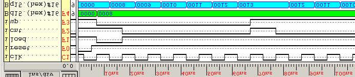
3 2. (30 points) Write a VHL specification for a loadable BC up-down counter with 4 digits. Your design should have three control signals load, cnt and up. When load is high, the circuit should load the value on the data inputs. Otherwise, when cnt is high, the circuit should increment by 1 if up is high and decrement by 1 if up is low. Your design should also have a synchronous reset that sets the counter to zero when asserted. Simulate your design first using a functional simulation with a 10 ns clock period. In your simulation, load the following values into the counter 8, 98, 998, 9998 and after each load, increment the counter 5 times and decrement it 5 times. Verify that your counter works correctly and turn in the result from this simulation, along with your VHL source code. Now, switch to a unit delay mode simulation. oes your design still work correctly? If not, explain why you think it is not working. Also, if it does not work, try doubling the clock period and checking the results again. If it still does not work, continue doubling the clock period until you find a clock period for which your design will work in the unit delay mode. Turn in samples of your simulation output for each of these runs, showing either that the circuit is working correctly, or that it is not. What do these results tell you about the operation speed of your circuit? library IEEE; use IEEE.std_logic_1164.all; use IEEE.std_logic_unsigned.all; -- bcd digit implements one decimal digit of BC up/down counter entity bcd_digit is port ( clk, reset: in ST_LOGIC; cnt, up, load: in ST_LOGIC; cbout: out ST_LOGIC; d: in ST_LOGIC_VECTOR (3 downto 0); q: out ST_LOGIC_VECTOR (3 downto 0) ); end bcd_digit; architecture bcd_digit_arch of bcd_digit is signal reg: ST_LOGIC_VECTOR (3 downto 0); begin process begin wait until clk = '1'; if reset = '1' then reg <= x"0"; elsif load = '1' then reg <= d; elsif cnt = '1' and up = '1' then if reg = x"9" then reg <= x"0"; else reg <= reg + x"1"; end if; elsif cnt = '1' and up = '0' then if reg = x"0" then reg <= x"9"; else - 3 -
4 reg <= reg - x"1"; end if; end if; end process; q <= reg; cbout <= '1' when (cnt = '1' and up = '1' and reg = x"9") or (cnt = '1' and up = '0' and reg = x"0") else '0'; end bcd_digit_arch; library IEEE; use IEEE.std_logic_1164.all; use IEEE.std_logic_unsigned.all; -- BC up-down counter. Resets to zero, counts when cnt high, -- counts up when up is also high, otherwise down entity bcdcntv is port ( clk, reset: in ST_LOGIC; cnt, up, load: in ST_LOGIC; d: in ST_LOGIC_VECTOR (15 downto 0); q: out ST_LOGIC_VECTOR (15 downto 0) ); end bcdcntv; architecture bcdcntv_arch of bcdcntv is component bcd_digit port ( clk, reset: in ST_LOGIC; cnt, up, load: in ST_LOGIC; cbout: out ST_LOGIC; d: in ST_LOGIC_VECTOR (3 downto 0); q: out ST_LOGIC_VECTOR (3 downto 0) ); end component; signal cb: ST_LOGIC_VECTOR(3 downto 0); begin d0: bcd_digit port map(clk,reset, cnt, up,load,cb(0),d( 3 downto 0),q( 3 downto 0)); d1: bcd_digit port map(clk,reset,cb(0),up,load,cb(1),d( 7 downto 4),q( 7 downto 4)); d2: bcd_digit port map(clk,reset,cb(1),up,load,cb(2),d(11 downto 8),q(11 downto 8)); d3: bcd_digit port map(clk,reset,cb(2),up,load,cb(3),d(15 downto 12),q(15 downto 12)); end bcdcntv_arch; The functional simulation results appear on the next page, and show the circuit working correctly for all the tested input conditions
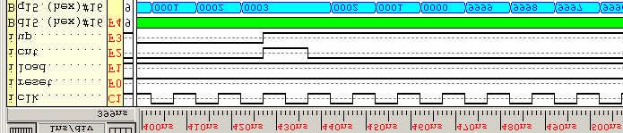
5 - 5 -


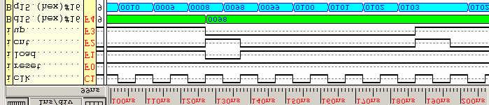
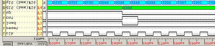
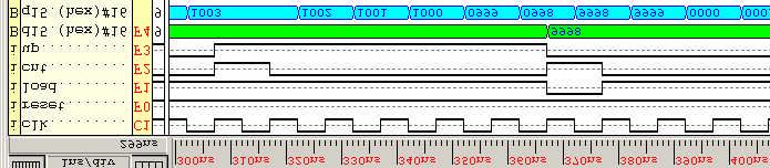
6 The simulation results below are from a unit delay simulation with a simulation precision of 1 ns and a 10 ns clock period. Although this was run for the same input values as the functional simulation, the results are obviously incorrect. Presumably, the gate delays are too high to allow the values to propagate through the combinational logic within the 10 ns available in each clock period. The results below are for a 20 ns clock period, and we can see that it seems to work somewhat better, but the load operation is still not working correctly. Apparently, it takes more than the 10 ns available for the data input values to propagate through the circuit s combinational logic to the flip flops. The results below are for a 40 ns clock period and here the load operation does work correctly, as do the counting operations. So, it appears that 20 ns is enough time for input values to propagate through to the flip flops. Overall, the results show that the counter works correctly, if the inputs are stable 20 ns before the clock goes high and the clock period is 40 ns or more. Clock periods close to 20 ns could work as well, but the inputs will have to be stable more than 10 ns before the clock edge in this case
EE 231 Fall EE 231 Homework 8 Due October 20, 2010
 EE 231 Homework 8 Due October 20, 20 1. Consider the circuit below. It has three inputs (x and clock), and one output (z). At reset, the circuit starts with the outputs of all flip-flops at 0. x z J Q
ECE 545 Lecture 6. Behavioral Modeling of Sequential-Circuit Building Blocks. Behavioral Design Style: Registers & Counters.
 ECE 55 Lecture 6 Behavioral Modeling of Sequential-Circuit Building Blocks Required reading P. Chu, RTL Hardware esign using VHL Chapter 5.1, VHL Process Chapter 8, Sequential Circuit esign: Principle
CSE 260 Introduction to Digital Logic and Computer Design. Exam 1 Solutions
 CSE 6 Introduction to igital Logic and Computer esign Exam Solutions Jonathan Turner /3/4. ( points) raw a logic diagram that implements the expression (B+C)(C +)(B+ ) directly (do not simplify first),
[VARIABLE declaration] BEGIN. sequential statements
![[VARIABLE declaration] BEGIN. sequential statements](/thumbs/89/98890993.jpg "[VARIABLE declaration] BEGIN. sequential statements") PROCESS statement (contains sequential statements) Simple signal assignment statement
PROCESS statement (contains sequential statements) Simple signal assignment statement
Counters. Counter Types. Variations. Modulo Gray Code BCD (Decimal) Decade Ring Johnson (twisted ring) LFSR
 Decade Ring Johnson (twisted ring) LFSR") CE 1911 Counters Counter Types Modulo Gray Code BC (ecimal) ecade Ring Johnson (twisted ring) LFSR Variations Asynchronous / Synchronous Up/own Loadable 2 tj Modulo-n (n = a power of 2) Asynchronous Count
CE 1911 Counters Counter Types Modulo Gray Code BC (ecimal) ecade Ring Johnson (twisted ring) LFSR Variations Asynchronous / Synchronous Up/own Loadable 2 tj Modulo-n (n = a power of 2) Asynchronous Count
Ripple Counters. Lecture 30 1
 Ripple Counters A register that goes through a prescribed sequence of states upon the application of input pulses is called a counter. The input pulses may be clock pulses, or they may originate from some
Problem Set 10 Solutions
 CSE 260 Digital Computers: Organization and Logical Design Problem Set 10 Solutions Jon Turner thru 6.20 1. The diagram below shows a memory array containing 32 words of 2 bits each. Label each memory
CSE 260 Introduction to Digital Logic and Computer Design. Exam 1. Your name 2/13/2014
 CSE 260 Introduction to Digital Logic and Computer Design Jonathan Turner Exam 1 Your name 2/13/2014 1. (10 points) Draw a logic diagram that implements the expression A(B+C)(C +D)(B+D ) directly (do not
Control Unit: Binary Multiplier. Arturo Díaz-Pérez Departamento de Computación Laboratorio de Tecnologías de Información CINVESTAV-IPN
 Control Unit: Binary Multiplier Arturo Díaz-Pérez Departamento de Computación Laboratorio de Tecnologías de Información CINVESTAV-IPN Example: Binary Multiplier Two versions Hardwired control Microprogrammed
DIGITAL LOGIC WITH VHDL (Fall 2013) Unit 6
 Unit 6") DIGITAL LOGIC WITH VHDL (Fall 2013) Unit 6 FINITE STATE MACHINES (FSMs) Moore Machines Mealy Machines FINITE STATE MACHINES (FSMs) Classification: Moore Machine: Outputs depend only on the current state
DIGITAL LOGIC WITH VHDL (Fall 2013) Unit 6 FINITE STATE MACHINES (FSMs) Moore Machines Mealy Machines FINITE STATE MACHINES (FSMs) Classification: Moore Machine: Outputs depend only on the current state
University of Technology
 University of Technology Lecturer: Dr. Sinan Majid Course Title: microprocessors 4 th year Lecture 13 Counters Overview Counters are important components in computers The increment or decrement by one
Lab 3: Standard Combinational Components
 Lab 3: Standard Combinational Components Purpose In this lab you will implement several combinational circuits on the DE1 development board to test and verify their operations. Introduction Using a high-level
DIGITAL LOGIC DESIGN VHDL Coding for FPGAs Unit 6
 DIGITAL LOGIC DESIGN VHDL Coding for FPGAs Unit 6 FINITE STATE MACHINES (FSMs) Moore Machines Mealy Machines Algorithmic State Machine (ASM) charts FINITE STATE MACHINES (FSMs) Classification: Moore Machine:
Control and Datapath 8
 Control and Datapath 8 Engineering attempts to develop design methods that break a problem up into separate steps to simplify the design and increase the likelihood of a correct solution. Digital system
COE 405, Term 062. Design & Modeling of Digital Systems. HW# 1 Solution. Due date: Wednesday, March. 14
 COE 405, Term 062 Design & Modeling of Digital Systems HW# 1 Solution Due date: Wednesday, March. 14 Q.1. Consider the 4-bit carry-look-ahead adder (CLA) block shown below: A 3 -A 0 B 3 -B 0 C 3 4-bit
Sequential Statement
 Sequential Statement Sequential Logic Output depends not only on current input values but also on previous input values. Are building blocks of; Counters Shift registers Memories Flip flops are basic sequential
Control in Digital Systems
 CONTROL CIRCUITS Control in Digital Systems Three primary components of digital systems Datapath (does the work) Control (manager, controller) Memory (storage) B. Baas 256 Control in Digital Systems Control
Midterm Exam Thursday, October 24, :00--2:15PM (75 minutes)
") Last (family) name: Answer Key First (given) name: Student I.D. #: Department of Electrical and Computer Engineering University of Wisconsin - Madison ECE 551 Digital System Design and Synthesis Midterm
Last (family) name: Answer Key First (given) name: Student I.D. #: Department of Electrical and Computer Engineering University of Wisconsin - Madison ECE 551 Digital System Design and Synthesis Midterm
DIGITAL LOGIC DESIGN VHDL Coding for FPGAs
 IGITAL LOGIC SIGN VHL Coding for FPGAs SUNTIAL CIRCUITS Unit 5 Asynchronous sequential circuits: Latches Synchronous circuits: flip flops, counters, registers. Testbench: Generating stimulus COMBINATIONAL
Outline. CPE/EE 422/522 Advanced Logic Design L05. Review: General Model of Moore Sequential Machine. Review: Mealy Sequential Networks.
 Outline CPE/EE 422/522 Advanced Logic Design L05 Electrical and Computer Engineering University of Alabama in Huntsville What we know Combinational Networks Sequential Networks: Basic Building Blocks,
VHDL Testbench. Test Bench Syntax. VHDL Testbench Tutorial 1. Contents
 VHDL Testbench Tutorial 1 Contents 1 VHDL Testbench 2 Test Bench Syntax 3 Testbench Example: VHDL Code for Up Down Binary Counter 4 VHDL Testbench code for up down binary counter 5 Testbench Waveform for
ELCT 501: Digital System Design
 ELCT 501: Digital System Lecture 4: CAD tools (Continued) Dr. Mohamed Abd El Ghany, Basic VHDL Concept Via an Example Problem: write VHDL code for 1-bit adder 4-bit adder 2 1-bit adder Inputs: A (1 bit)
CS232 VHDL Lecture. Types
 CS232 VHDL Lecture VHSIC Hardware Description Language [VHDL] is a language used to define and describe the behavior of digital circuits. Unlike most other programming languages, VHDL is explicitly parallel.
Timing in synchronous systems
 BO 1 esign of sequential logic Outline Timing in synchronous networks Synchronous processes in VHL VHL-code that introduces latches andf flip-flops Initialization of registers Mealy- and Moore machines
Part 4: VHDL for sequential circuits. Introduction to Modeling and Verification of Digital Systems. Memory elements. Sequential circuits
 M1 Informatique / MOSIG Introduction to Modeling and erification of Digital Systems Part 4: HDL for sequential circuits Laurence PIERRE http://users-tima.imag.fr/amfors/lpierre/m1arc 2017/2018 81 Sequential
Digital Integrated Circuits
 Digital Integrated Circuits Lecture 4 Jaeyong Chung System-on-Chips (SoC) Laboratory Incheon National University BCD TO EXCESS-3 CODE CONVERTER 0100 0101 +0011 +0011 0111 1000 LSB received first Chung
EL 310 Hardware Description Languages Midterm
 EL 3 Hardware Description Languages Midterm 2 3 4 5 Total Name: ID : Notes: ) Please answer the questions in the provided space after each question. 2) Duration is minutes 3) Closed books and closed notes.
Contents. Chapter 9 Datapaths Page 1 of 28
 Chapter 9 Datapaths Page of 2 Contents Contents... 9 Datapaths... 2 9. General Datapath... 3 9.2 Using a General Datapath... 5 9.3 Timing Issues... 7 9.4 A More Complex General Datapath... 9 9.5 VHDL for
Sequential Logic - Module 5
 Sequential Logic Module 5 Jim Duckworth, WPI 1 Latches and Flip-Flops Implemented by using signals in IF statements that are not completely specified Necessary latches or registers are inferred by the
EE 459/500 HDL Based Digital Design with Programmable Logic. Lecture 6 Combinational and sequential circuits
 EE 459/5 HL Based igital esign with Programmable Logic Lecture 6 ombinational and sequential circuits Read before class: hapter 2 from textbook Overview ombinational circuits Multiplexer, decoders, encoders,
Testbenches for Sequential Circuits... also, Components
 ! Testbenches for Sequential Circuits... also, Components Lecture L04 18-545 Advanced Digital Design ECE Department Many elements Don Thomas, 2014, used with permission with credit to G. Larson State Transition
EECE 353: Digital Systems Design Lecture 10: Datapath Circuits
 EECE 353: Digital Systems Design Lecture 10: Datapath Circuits Cristian Grecu grecuc@ece.ubc.ca Course web site: http://courses.ece.ubc.ca/353 Introduction to lecture 10 Large digital systems are more
Summary of FPGA & VHDL
 FYS4220/9220 Summary of FPGA & VHDL Lecture #6 Jan Kenneth Bekkeng, University of Oslo - Department of Physics 16.11.2011 Curriculum (VHDL & FPGA part) Curriculum (Syllabus) defined by: Lectures Lecture6:
Injntu.com Injntu.com Injntu.com R16
 1. a) What are the three methods of obtaining the 2 s complement of a given binary (3M) number? b) What do you mean by K-map? Name it advantages and disadvantages. (3M) c) Distinguish between a half-adder
CSE 260 Digital Computers: Organization and Logical Design. Exam 2. Jon Turner 3/28/2012
 CSE 260 Digital Computers: Organization and Logical Design Exam 2 Jon Turner 3/28/2012 1. (15 points). Draw a diagram for a circuit that implements the VHDL module shown below. Your diagram may include
ECE 545 Lecture 6. Behavioral Modeling of Sequential-Circuit Building Blocks. George Mason University
 ECE 545 Lecture 6 Behavioral Modeling of Sequential-Circuit Building Blocks George Mason University Required reading P. Chu, RTL Hardware Design using VHDL Chapter 5.1, VHDL Process Chapter 8, Sequential
Chapter 10. Counters (a short discussion)
") EE2L_ClassNotes_Ch_Counters_transparencies.fm Chapter Counters (a short discussion) ecimal count sequence: Ex: 788, 789, 79,... Ex: 798, 799, 8,... Generalization: 2 Binary count sequence: In a multi-bit
EE2L_ClassNotes_Ch_Counters_transparencies.fm Chapter Counters (a short discussion) ecimal count sequence: Ex: 788, 789, 79,... Ex: 798, 799, 8,... Generalization: 2 Binary count sequence: In a multi-bit
Lecture 12 VHDL Synthesis
 CPE 487: Digital System Design Spring 2018 Lecture 12 VHDL Synthesis Bryan Ackland Department of Electrical and Computer Engineering Stevens Institute of Technology Hoboken, NJ 07030 1 What is Synthesis?
FPGA Design Challenge :Techkriti 14 Digital Design using Verilog Part 1
 FPGA Design Challenge :Techkriti 14 Digital Design using Verilog Part 1 Anurag Dwivedi Digital Design : Bottom Up Approach Basic Block - Gates Digital Design : Bottom Up Approach Gates -> Flip Flops Digital
CSE 260 Digital Computers: Organization and Logical Design. Exam 2 Solutions
 CSE 260 Digital Computers: Organization and Logical Design Exam 2 Solutions Jon Turner 1. (10 points). The table at right shows a table with 5 rows and three columns with each column having a heading.
3 Designing Digital Systems with Algorithmic State Machine Charts
 3 Designing with Algorithmic State Machine Charts An ASM chart is a method of describing the sequential operations of a digital system which has to implement an algorithm. An algorithm is a well defined
Pollard s Tutorial on Clocked Stuff in VHDL
 Pollard s Tutorial on Clocked Stuff in VHDL Welcome to a biased view of how to do register type of stuff in VHDL. The object of this short note is to identify one way to easily handle registered logic
Design Problem 3 Solutions
 CSE 260 Digital Computers: Organization and Logical Design Jon Turner Design Problem 3 Solutions In this problem, you are to design, simulate and implement a sequential pattern spotter, using VHDL. This
Nanosistemų programavimo kalbos 5 paskaita. Sekvencinių schemų projektavimas
 Nanosistemų programavimo kalbos 5 paskaita Sekvencinių schemų projektavimas Terminai Combinational circuit kombinacinė schema (be atminties elementų) Sequential circuit nuosekli (trigerinė, sekvencinė)
ECE 448 Lecture 4. Sequential-Circuit Building Blocks. Mixing Description Styles
 ECE 448 Lecture 4 Sequential-Circuit Building Blocks Mixing Description Styles George Mason University Reading Required P. Chu, FPGA Prototyping by VHDL Examples Chapter 4, Regular Sequential Circuit Recommended
The UNIVERSITY of NORTH CAROLINA at CHAPEL HILL
 The UNIVERSITY of NORTH CAROLINA at CHAPEL HILL Comp 541 Digital Logic and Computer Design Fall 2014 Lab #4: Sequential Design: Counters Issued Wed 9/10/14; Due Wed 9/17/14 (11:59pm) This lab assignment
Two HDLs used today VHDL. Why VHDL? Introduction to Structured VLSI Design
 Two HDLs used today Introduction to Structured VLSI Design VHDL I VHDL and Verilog Syntax and ``appearance'' of the two languages are very different Capabilities and scopes are quite similar Both are industrial
VHDL Simulation. Testbench Design
 VHDL Simulation Testbench Design The Test Bench Concept Elements of a VHDL/Verilog testbench Unit Under Test (UUT) or Device Under Test (DUT) instantiate one or more UUT s Stimulus of UUT inputs algorithmic
EECS150, Fall 2004, Midterm 1, Prof. Culler. Problem 1 (15 points) 1.a. Circle the gate-level circuits that DO NOT implement a Boolean AND function.
 1.a. Circle the gate-level circuits that DO NOT implement a Boolean AND function.") Problem 1 (15 points) 1.a. Circle the gate-level circuits that DO NOT implement a Boolean AND function. 1.b. Show that a 2-to-1 MUX is universal (i.e. that any Boolean expression can be implemented with
Problem 1 (15 points) 1.a. Circle the gate-level circuits that DO NOT implement a Boolean AND function. 1.b. Show that a 2-to-1 MUX is universal (i.e. that any Boolean expression can be implemented with
EECS150 - Digital Design Lecture 20 - Finite State Machines Revisited
 EECS150 - Digital Design Lecture 20 - Finite State Machines Revisited April 2, 2009 John Wawrzynek Spring 2009 EECS150 - Lec20-fsm Page 1 Finite State Machines (FSMs) FSM circuits are a type of sequential
ECE 574: Modeling and Synthesis of Digital Systems using Verilog and VHDL. Fall 2017 Final Exam (6.00 to 8.30pm) Verilog SOLUTIONS
 Verilog SOLUTIONS") ECE 574: Modeling and Synthesis of Digital Systems using Verilog and VHDL Fall 2017 Final Exam (6.00 to 8.30pm) Verilog SOLUTIONS Note: Closed book no notes or other material allowed apart from the one
ECE 574: Modeling and Synthesis of Digital Systems using Verilog and VHDL Fall 2017 Final Exam (6.00 to 8.30pm) Verilog SOLUTIONS Note: Closed book no notes or other material allowed apart from the one
VHDL/Verilog Simulation. Testbench Design
 VHDL/Verilog Simulation Testbench Design The Test Bench Concept Elements of a VHDL/Verilog testbench Unit Under Test (UUT) or Device Under Test (DUT) instantiate one or more UUT s Stimulus of UUT inputs
Written exam for IE1204/5 Digital Design Thursday 29/
 Written exam for IE1204/5 Digital Design Thursday 29/10 2015 9.00-13.00 General Information Examiner: Ingo Sander. Teacher: William Sandqvist phone 08-7904487 Exam text does not have to be returned when
ECEU530. Homework 4 due Wednesday Oct 25. ECE U530 Digital Hardware Synthesis. VHDL for Synthesis with Xilinx. Schedule
 EEU530 EE U530 igital Hardware Synthesis Lecture 11: Prof. Miriam Leeser mel@coe.neu.edu October 18, 2005 Sequential Logic in VHL Finite State Machines in VHL Project proposals due now HW 4 due Wednesday,
Code No: R Set No. 1
 Code No: R059210504 Set No. 1 II B.Tech I Semester Regular Examinations, November 2006 DIGITAL LOGIC DESIGN ( Common to Computer Science & Engineering, Information Technology and Computer Science & Systems
Schedule. ECE U530 Digital Hardware Synthesis. Rest of Semester. Midterm Question 1a
 ECE U530 Digital Hardware Synthesis Prof. Miriam Leeser mel@coe.neu.edu November 8, 2006 Midterm Average: 70 Lecture 16: Midterm Solutions Homework 6: Calculator Handshaking HW 6: Due Wednesday, November
Concurrent & Sequential Stmts. (Review)
") VHDL Introduction, Part II Figures in this lecture are from: Rapid Prototyping of Digital Systems, Second Edition James O. Hamblen & Michael D. Furman, Kluwer Academic Publishers, 2001, ISBN 0-7923-7439-
VHDL Introduction, Part II Figures in this lecture are from: Rapid Prototyping of Digital Systems, Second Edition James O. Hamblen & Michael D. Furman, Kluwer Academic Publishers, 2001, ISBN 0-7923-7439-
Code No: R Set No. 1
 Code No: R059210504 Set No. 1 II B.Tech I Semester Supplementary Examinations, February 2007 DIGITAL LOGIC DESIGN ( Common to Computer Science & Engineering, Information Technology and Computer Science
VHDL. VHDL History. Why VHDL? Introduction to Structured VLSI Design. Very High Speed Integrated Circuit (VHSIC) Hardware Description Language
 Hardware Description Language") VHDL Introduction to Structured VLSI Design VHDL I Very High Speed Integrated Circuit (VHSIC) Hardware Description Language Joachim Rodrigues A Technology Independent, Standard Hardware description Language
VHDL Introduction to Structured VLSI Design VHDL I Very High Speed Integrated Circuit (VHSIC) Hardware Description Language Joachim Rodrigues A Technology Independent, Standard Hardware description Language
Code No: R Set No. 1
 Code No: R059210504 Set No. 1 II B.Tech I Semester Regular Examinations, November 2007 DIGITAL LOGIC DESIGN ( Common to Computer Science & Engineering, Information Technology and Computer Science & Systems
Lecture 4: Modeling in VHDL (Continued ) EE 3610 Digital Systems
 EE 3610 Digital Systems") EE 3610: Digital Systems 1 Lecture 4: Modeling in VHDL (Continued ) Sequential Statements Use Process process (sensitivity list) variable/constant declarations Sequential Statements end process; 2 Sequential
EE 3610: Digital Systems 1 Lecture 4: Modeling in VHDL (Continued ) Sequential Statements Use Process process (sensitivity list) variable/constant declarations Sequential Statements end process; 2 Sequential
RealDigital. Problem Set #7 S1 S2 S3 Y Z X Y + Y Z X Z
 Problem Set #7 RealDigital 1. (10 points) Modify the state diagram branching conditions in the diagrams below as needed to ensure the sum and exclusion rules are obeyed in each case. You can add a holding
VHDL Testbench Design. Textbook chapters 2.19, , 9.5
 VHDL Testbench Design Textbook chapters 2.19, 4.10-4.12, 9.5 The Test Bench Concept Elements of a VHDL/Verilog testbench Unit Under Test (UUT) or Device Under Test (DUT) instantiate one or more UUT s Stimulus
6.111 Lecture # 8. Topics for Today: (as time permits)
") 6.111 Lecture # 8 Topics for Today: (as time permits) 1. Memories 2. Assembling 'packages' for designs 3. Discussion of design procedure 4. Development of a design example using a finite state machine
6.111 Lecture # 8 Topics for Today: (as time permits) 1. Memories 2. Assembling 'packages' for designs 3. Discussion of design procedure 4. Development of a design example using a finite state machine
VHDL: RTL Synthesis Basics. 1 of 59
 VHDL: RTL Synthesis Basics 1 of 59 Goals To learn the basics of RTL synthesis. To be able to synthesize a digital system, given its VHDL model. To be able to relate VHDL code to its synthesized output.
EPC6055 Digital Integrated Circuits EXAM 1 Fall Semester 2013
 EPC6055 Digital Integrated Circuits EXAM 1 Fall Semester 2013 Print Here Student ID Signature This is a closed book exam. The exam is to be completed in one-hundred ten (110) minutes. Don t use scratch
Computer-Aided Digital System Design VHDL
 بس م اهلل الر حم ن الر حی م Iran University of Science and Technology Department of Computer Engineering Computer-Aided Digital System Design VHDL Ramin Rajaei ramin_rajaei@ee.sharif.edu Modeling Styles
R07
 www..com www..com SET - 1 II B. Tech I Semester Supplementary Examinations May 2013 SWITCHING THEORY AND LOGIC DESIGN (Com. to EEE, EIE, BME, ECC) Time: 3 hours Max. Marks: 80 Answer any FIVE Questions
Latch Based Design (1A) Young Won Lim 2/18/15
 Young Won Lim 2/18/15") Latch Based Design (1A) Copyright (c) 2015 Young W. Lim. Permission is granted to copy, distribute and/or modify this document under the terms of the GNU Free Documentation License, Version 1.2 or any
Latch Based Design (1A) Copyright (c) 2015 Young W. Lim. Permission is granted to copy, distribute and/or modify this document under the terms of the GNU Free Documentation License, Version 1.2 or any
VHDL for Modeling - Module 10
 VHDL for Modeling Module 10 Jim Duckworth, WPI 1 Overview General examples AND model Flip-flop model SRAM Model Generics DDR SDRAM Model Constraints Metastability Block Statements Just for reference Jim
MASSACHUSETTS INSTITUTE OF TECHNOLOGY Department of Electrical Engineering and Computer Sciences
 MASSACHUSETTS INSTITUTE OF TECHNOLOGY Department of Electrical Engineering and Computer Sciences Introductory Digital Systems Lab (6.111) uiz - Spring 2004 Prof. Anantha Chandrakasan Student Name: Problem
Inferring Storage Elements
 Inferring Storage Elements In our designs, we usually use flip-flops as our storage elements. Sometimes we use latches, but not often. Latches are smaller in size, but create special, often difficult situations
Single Cycle Datapath
 Single Cycle atapath Lecture notes from MKP, H. H. Lee and S. Yalamanchili Section 4.-4.4 Appendices B.7, B.8, B.,.2 Practice Problems:, 4, 6, 9 ing (2) Introduction We will examine two MIPS implementations
Sequential Circuit Design: Principle
 Sequential Circuit Design: Principle Chapter 8 1 Outline 1. Overview on sequential circuits 2. Synchronous circuits 3. Danger of synthesizing async circuit 4. Inference of basic memory elements 5. Simple
VHDL VS VERILOG.
 1 VHDL VS VERILOG http://www.cse.cuhk.edu.hk/~mcyang/teaching.html 2 VHDL & Verilog They are both hardware description languages for modeling hardware. They are each a notation to describe the behavioral
ECOM 4311 Digital Systems Design
 ECOM 4311 Digital Systems Design Eng. Monther Abusultan Computer Engineering Dept. Islamic University of Gaza Page 1 Agenda 1. Counters Page 2 Counters - special name of any clocked sequential circuit
The University of Alabama in Huntsville Electrical and Computer Engineering CPE/EE 422/522 Spring 2005 Homework #6 Solution
 5.3(a)(2), 5.6(c)(2), 5.2(2), 8.2(2), 8.8(2) The University of Alabama in Huntsville Electrical and Computer Engineering CPE/EE 422/522 Spring 25 Homework #6 Solution 5.3 (a) For the following SM chart:
Lecture 3. Behavioral Modeling Sequential Circuits. Registers Counters Finite State Machines
 Lecture 3 Behavioral Modeling Sequential Circuits Registers Counters Finite State Machines Behavioral Modeling Behavioral Modeling Behavioral descriptions use the keyword always, followed by optional event
Mid-Term Exam Solutions
 CS/EE 26 Digital Computers: Organization and Logical Design Mid-Term Eam Solutions Jon Turner 3/3/3. (6 points) List all the minterms for the epression (B + A)C + AC + BC. Epanding the epression gives
Digital Circuit Design and Language. Datapath Design. Chang, Ik Joon Kyunghee University
 Digital Circuit Design and Language Datapath Design Chang, Ik Joon Kyunghee University Typical Synchronous Design + Control Section : Finite State Machine + Data Section: Adder, Multiplier, Shift Register
EEL 4712 Digital Design Test 1 Spring Semester 2007
 IMPORTANT: Please be neat and write (or draw) carefully. If we cannot read it with a reasonable effort, it is assumed wrong. COVER SHEET: Problem: Points: 1 (15 pts) 2 (20 pts) Total 3 (15 pts) 4 (18 pts)
L5: Simple Sequential Circuits and Verilog
 L5: Simple Sequential Circuits and Verilog Courtesy of Rex Min. Used with permission. 1 Key Points from L4 (Sequential Blocks) Classification: Latch: level sensitive (positive latch passes input to output
ENSC E-123: HW D3: Counter Applications; Counter in Verilog
 HW D3; Counter Applications 1 ENSC E-123: HW D3: Counter Applications; Counter in Verilog REV 0 1 ; February 12, 2015 Contents 1 Counter Applications: Sync vs Async Function (5 points) 2 1.1 Crummy: asyncclear(2points).................
Lectures 11 & 12: Synchronous Sequential Circuits Minimization
 Lectures & 2: Synchronous Sequential Circuits Minimization. This week I noted that our seven-state edge detector machine on the left side below could be simplified to a five-state machine on the right.
C A R L E T O N U N I V E R S I T Y. FINAL EXAMINATION April Duration: 3 Hours No. of Students: 108
 C A R L E T O N U N I V E R S I T Y FINAL EXAMINATION April 2011 Duration: 3 Hours No. of Students: 108 Department Name & Course Number: ELEC 3500 Digital Electronics Course Instructor(s): Ralph Mason
Design Problem 4 Solutions
 CSE 260 Digital Computers: Organization and Logical Design Design Problem 4 Solutions Jon Turner The block diagram appears below. The controller includes a state machine with three states (normal, movecursor,
Verilog Fundamentals. Shubham Singh. Junior Undergrad. Electrical Engineering
 Verilog Fundamentals Shubham Singh Junior Undergrad. Electrical Engineering VERILOG FUNDAMENTALS HDLs HISTORY HOW FPGA & VERILOG ARE RELATED CODING IN VERILOG HDLs HISTORY HDL HARDWARE DESCRIPTION LANGUAGE
ECEU530. Schedule. ECE U530 Digital Hardware Synthesis. Datapath for the Calculator (HW 5) HW 5 Datapath Entity
 HW 5 Datapath Entity") ECE U530 Digital Hardware Synthesis Prof. Miriam Leeser mel@coe.neu.edu November 6, 2006 Classes November 6 and 8 are in 429 Dana! Lecture 15: Homework 5: Datapath How to write a testbench for synchronous
ECE U530 Digital Hardware Synthesis Prof. Miriam Leeser mel@coe.neu.edu November 6, 2006 Classes November 6 and 8 are in 429 Dana! Lecture 15: Homework 5: Datapath How to write a testbench for synchronous
Introduction to VHDL #3
 ECE 322 Digital Design with VHDL Introduction to VHDL #3 Lecture 7 & 8 VHDL Modeling Styles VHDL Modeling Styles Dataflow Concurrent statements Structural Components and interconnects Behavioral (sequential)
Single Cycle Datapath
 Single Cycle atapath Lecture notes from MKP, H. H. Lee and S. Yalamanchili Section 4.1-4.4 Appendices B.3, B.7, B.8, B.11,.2 ing Note: Appendices A-E in the hardcopy text correspond to chapters 7-11 in
VHDL. ELEC 418 Advanced Digital Systems Dr. Ron Hayne. Images Courtesy of Cengage Learning
 VHDL ELEC 418 Advanced Digital Systems Dr. Ron Hayne Images Courtesy of Cengage Learning Design Flow 418_02 2 VHDL Modules 418_02 3 VHDL Libraries library IEEE; use IEEE.std_logic_1164.all; std_logic Single-bit
ACS College of Engineering. Department of Biomedical Engineering. Logic Design Lab pre lab questions ( ) Cycle-1
 Cycle-1") ACS College of Engineering Department of Biomedical Engineering Logic Design Lab pre lab questions (2015-2016) Cycle-1 1. What is a combinational circuit? 2. What are the various methods of simplifying
ACS College of Engineering Department of Biomedical Engineering Logic Design Lab pre lab questions (2015-2016) Cycle-1 1. What is a combinational circuit? 2. What are the various methods of simplifying
Design Problem 4 Solution
 CSE 260 Digital Computers: Organization and Logical Design Design Problem 4 Solution Jon Turner Due 4/13/06 1. (125 points). In this problem, you will design a packet FIFO, which is a circuit that temporarily
Digital Design with SystemVerilog
 Digital Design with SystemVerilog Prof. Stephen A. Edwards Columbia University Spring 25 Synchronous Digital Design Combinational Logic Sequential Logic Summary of Modeling Styles Testbenches Why HDLs?
Mealy and Moore examples
 CSE 37 Spring 26 Introduction to igital esign ecture 2: uential ogic Technologies ast ecture Moore and Mealy Machines Today uential logic technologies Ving machine: Moore to synch. Mealy OPEN = creates
Lab 6: Integrated the Decoder with Muti-bit Counter and Programming a FPGA
 Lab 6: Integrated the Decoder with Muti-bit Counter and Programming a FPGA For your report: The problem written in English The flowchart or function table to solve the problem if it is necessary The design
EECS 373 Midterm 2 Fall 2018
 EECS 373 Midterm 2 Fall 2018 Name: unique name: Sign the honor code: I have neither given nor received aid on this exam nor observed anyone else doing so. Nor did I discuss this exam with anyone after
VHDL simulation and synthesis
 VHDL simulation and synthesis How we treat VHDL in this course You will not become an expert in VHDL after taking this course The goal is that you should learn how VHDL can be used for simulation and synthesis
DESCRIPTION OF DIGITAL CIRCUITS USING VHDL
 DESCRIPTION OF DIGITAL CIRCUITS USING VHDL Combinatinal circuits Sequential circuits Design organization. Generic design Iterative operations Authors: Luis Entrena Arrontes, Celia López, Mario García,
Test Benches - Module 8
 Test Benches Module 8 Jim Duckworth, WPI 1 Overview We have concentrated on VHDL for synthesis Can also use VHDL as a test language Very important to conduct comprehensive verification on your design To