VBA with SOLIDWORKS (Base Solid Model) Lecture 61
|
|
|
- Joy Briggs
- 5 years ago
- Views:
Transcription
1 VBA 4 VBA with SOLIDWORKS (Base Solid Model) Lecture 61 1
2 Basic Procedure 1. Set the plane 2. Draw the profiles using sketch entities 3. Create the base model (Step 1 and 2: has learnt from previous slide) Lecture 6 2


3 Extruded: Refresher Lecture 6 3

4 Extruded Base Model pfeat = FeatureManager.FeatureExtrusion2 FeatureExtrusion2 ( sd, flip, dir, t1, t2, d1, d2, dchk1, dchk2, ddir1, ddir2, dang1, dang2, offsetreverse1, offsetreverse2, translatesurface1, translatesurface2, merge, usefeatscope, useautoselect, t0, startoffset, flipstartoffset ) sd: flip dir TRUE: single ended FALSE: double ended TRUE to flip the direction to cut (not applicable for base mode) TRUE to flip the direction to extrude t1 t2 Lecture 6 4


 d1 in meters ddir1:")

5 pfeat = FeatureManager.FeatureExtrusion2 ( sd, flip, dir, t1, t2, d1, d2, dchk1, dchk2, ddir1, ddir2, dang1, dang2, offsetreverse1, offsetreverse2, translatesurface1, translatesurface2, merge, usefeatscope, useautoselect, t0, startoffset, flipstartoffset ) d1 in meters ddir1: TRUE: inward dchk1: TRUE for drafting d2 in meters dchk2: TRUE for drafting FALSE: outward dang1: draft angle ddir2: TRUE: inward FALSE: outward dang2: draft angle Lecture 6 5
6 Parameters: default values pfeat = FeatureManager.FeatureExtrusion2 ( sd, flip, dir, t1, t2, d1, d2, dchk1, dchk2, ddir1, ddir2, dang1, dang2, offsetreverse1, offsetreverse2, translatesurface1, translatesurface2, merge, usefeatscope, useautoselect, t0, startoffset, flipstartoffset ) OffsetReverse1 False, OffsetReverse2 False, trabslatesurface1 False, translatesurface2 False, Merge False, usefeatscope: False, useautoselect: False t0 0 startoffset: 0 flipstartoffset: False Set base = Part.FeatureManager.FeatureExtrusion2(True, False, False, 0, 0, 10, 0, False, False, False, False, 0, 0, False, False, False, False, False, False, False, 0, 0, False) Example: extrude.swp Lecture 6 6

 Set line3 = Part.")
 Set consline = Part.")
7 Revolved Base Model Base Profile Axis of revolution Dim line1, line2, line3, line4, consline As Object Set line1 = Part.CreateLine2(5, 5, 0, 5, -5, 0) Set line2 = Part.CreateLine2(5, -5, 0, -5, -5, 0) Set line3 = Part.CreateLine2(-5, -5, 0, -5, 5, 0) Set line4 = Part.CreateLine2(-5, 5, 0, 5, 5, 0) Set consline = Part.CreateLine2(10, 5, 0, 10, - 5, 0) consline.constructiongeometry = True Lecture 6 7


8 Revolved Base Model 5 10 Lecture 6 8
 Angle1: in radian reversedir: True: reverse the direction False: not Angle2: in radian")
9 Revolved Base Model retval = FeatureManager.FeatureRevolve FeatureRevolve ( angle, reversedir, angle2, revtype, options, merge, usefeatscope, useautosel ) Angle1: in radian reversedir: True: reverse the direction False: not Angle2: in radian revtype: swrevolveonedirection swrevolvetypemidplane swrevolvetypetwodirection Etc (refer to online help) Other parameters Options: 0 Merge: False usefeatscope: False useautosel: False Lecture 6 9


10 Revolved Base Model revolve.swp Dim base As Object Set base = Part.FeatureManager.FeatureRevolve (3.14, False, 0, swrevolveonedirection, 0, False, False, False) Lecture 6 10


11 Thin Feature FeatureRevolveThin (additional parameters: thickness 1 and thickness 2) FeatureExtrusion2 (additional parameters: thickness 1 and thickness 2) Lecture 6 11
12 Create Sub Component Procedure 1. Select the face where the profiles to be drawn 2. Draw the profiles Similar to the profile creation in sketch. 3. Create the model to cut or extrude Lecture 6 12
13 Select the face to create the plane 1. Select the face boolstatus = Part.Extension.SelectByID2("", "FACE", 1, 1, 0, False, 0, Nothing, 0) 2. Create the plane Part.SketchManager.InsertSketch True * The coordinate set in the selection set must be the point on the intended face. Lecture 6 13
14 Create the cut or extruded feature 1. Extruded d feature: use the FeatureExtrusion2 command 2. Cut feature: use FeatureCut command pfeat = FeatureManager.FeatureCut ( sd, flip, dir, t1, t2, d1, d2, dchk1, dchk2, ddir1, ddir2, dang1, dang2, offsetreverse1, offsetreverse2, translatesurface1, translatesurface2, normalcut, usefeatscope, useautoselect ) * all the parameters are similar to FeatureExtrusion2 Lecture 6 14
 Set line3 = Part.CreateLine2(2, 1, 0, 2, 3, 0) Set line4 = Part.")
15 Example: cut feature boolstatus = Part.Extension.SelectByID2( SelectByID2("", "FACE", 1, 1, 0, False, 0, Nothing, 0) Part.SketchManager.InsertSketch True Dim line2, line3, line4, line5, base2 As Object Set line2 = Part.CreateLine2(-2, 1, 0, 2, 1, 0) Set line3 = Part.CreateLine2(2, 1, 0, 2, 3, 0) Set line4 = Part.CreateLine2(2, 3, 0, -2, 3, 0) Set line5 = Part.CreateLine2(-2, 3, 0, -2, 1, 0) Set base2 = Part.FeatureManager.FeatureCut(True, False, False, swendcondthroughall, 0, 0, 0, False, False, False, False, 0, 0, False, False, False, False, 0, 1, 1) Note: when swendcondthroughall (t1) is used, the distance to cut can be set to 0. Lecture 6 15


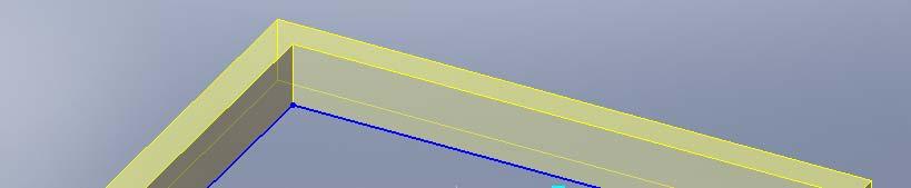
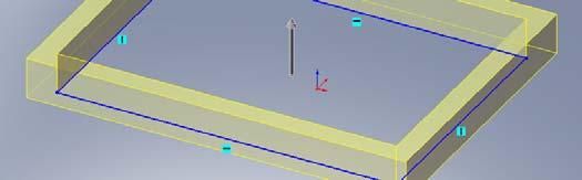
16 Shell Part.SketchRectangle -0.04, -0.04, 0, 0.04, 0.04, 0, 1 Part.FeatureManager.FeatureExtrusion2 True, False, False, 0, 0, 0.04, 0, False, False, False, False, 0, 0, False, False, False, False, False, False, False, 0, 0, False boolstatus = Part.Extension.SelectByID2("", "FACE", 0, 0.04, 0, False, 0, Nothing, 0) Part.InsertFeatureShell 0.005, False Lecture 6 16
17 Assignment 2 Write the subroutine that t will draw the linkages for the projects. The subroutine will need the length, angle of orientation and insertion points. Lecture 6 17
18 Major Project Your task is to write a program to builtset the point, determine whether the body can reachable and angle required. Lecture 6 18
SolidWorks 2006 API 1
 SolidWorks 2006 API 1 Human Centered CAD Laboratory 1 2009-04-16 About The Goal The goal of this course is to introduce you the SolidWorks 2006 Application Programming Interface(API). Using the SolidWorks
Extrusion Revolve. ENGR 1182 SolidWorks 02
 Extrusion Revolve ENGR 1182 SolidWorks 02 Today s Objectives Creating 3D Shapes from 2D sketches using: Extrusion Revolve SW02 In-Class Activity Extrude a Camera Revolve a Wheel SW02 Out-of-Class Homework
Feature-Based Modeling and Optional Advanced Modeling. ENGR 1182 SolidWorks 05
 Feature-Based Modeling and Optional Advanced Modeling ENGR 1182 SolidWorks 05 Today s Objectives Feature-Based Modeling (comprised of 2 sections as shown below) 1. Breaking it down into features Creating
SOLIDWORKS: Lesson III Patterns & Mirrors. UCF Engineering
 SOLIDWORKS: Lesson III Patterns & Mirrors UCF Engineering Solidworks Review Last lesson we discussed several more features that can be added to models in order to increase their complexity. We are now
CO2 Shell Car. Axle Retainer. in the Feature Manager and click Sketch from the Content toolbar, Fig. 1. (L) on the Sketch toolbar. Fig.
 on the Sketch toolbar. Fig.") Chapter 17 CO2 Shell Car Axle Retainer A. Sketch. Step 1. Click File Menu > New, click Part Metric and OK. Step 2. Click Top Plane in the Feature Manager and click Sketch from the Content toolbar, Fig.
Chapter 17 CO2 Shell Car Axle Retainer A. Sketch. Step 1. Click File Menu > New, click Part Metric and OK. Step 2. Click Top Plane in the Feature Manager and click Sketch from the Content toolbar, Fig.
Delta Dart. Socket. (L) on the Sketch toolbar. Fig. 1. (S) on the Sketch toolbar. on the Sketch toolbar. on the Standard Views toolbar.
 on the Sketch toolbar. Fig. 1. (S) on the Sketch toolbar. on the Sketch toolbar. on the Standard Views toolbar.") Chapter 6 Delta Dart Socket A. Sketch. Step 1. Click File Menu > New, click Part Metric and OK. Step 2. Click Front Plane in the Feature Manager and click Sketch from the Content toolbar, Fig. 1. Step
Chapter 6 Delta Dart Socket A. Sketch. Step 1. Click File Menu > New, click Part Metric and OK. Step 2. Click Front Plane in the Feature Manager and click Sketch from the Content toolbar, Fig. 1. Step
Introduction to ANSYS DesignModeler
 Lecture 5 Modeling 14. 5 Release Introduction to ANSYS DesignModeler 2012 ANSYS, Inc. November 20, 2012 1 Release 14.5 Preprocessing Workflow Geometry Creation OR Geometry Import Geometry Operations Meshing
JSS. Ping Pong Ball. in the Feature Manager and click Sketch on the Context toolbar, Fig. 1. on the Sketch toolbar.
 Chapter 18 JSS Ping Pong Ball A. Half Circle Sketch. Step 1. Click File Menu > New, click Part Metric and OK. Step 2. Click Front Plane in the Feature Manager and click Sketch on the Context toolbar, Fig.
Solid Bodies and Disjointed Bodies
 Solid Bodies and Disjointed Bodies Generally speaking when modelling in Solid Works each Part file will contain single solid object. As you are modelling, each feature is merged or joined to the previous
MAE 455 COMPUTER-AIDED DESIGN AND DRAFTING MIDTERM EXAM PRACTICE QUESTIONS. Name: You are allowed one sheet of notes.
 47 MAE 455 COMPUTER-AIDED DESIGN AND DRAFTING MIDTERM EXAM PRACTICE QUESTIONS Name: You are allowed one sheet of notes. 1. What constraints could be added to fully constrain the wireframe shown? Include
CATIA V5 Parametric Surface Modeling
 CATIA V5 Parametric Surface Modeling Version 5 Release 16 A- 1 Toolbars in A B A. Wireframe: Create 3D curves / lines/ points/ plane B. Surfaces: Create surfaces C. Operations: Join surfaces, Split & Trim
Introduction to Solid Modeling
 Introduction to Solid Modeling Parametric Modeling 1 Why draw 3D Models? 3D models are easier to interpret. 3D models can be used to perform engineering analysis, finite element analysis (stress, deflection,
Wheel GT-F. Chapter 5. CO2 Shell Car. A. Sketch. Step 1. Click File Menu > New, click Part Metric and OK.
 Chapter 5 CO2 Shell Car Wheel GT-F A. Sketch. Step 1. Click File Menu > New, click Part Metric and OK. Step 2. Click Front Plane in the Feature Manager and click Sketch on the context toolbar, Fig. 1.
ME Week 3 Project 3 - Plastic Part Thicken Method
 Plastic Part Commands The following section will give a further overview of the Autodesk Inventor plastic part commands. 1. Project 3 This project will further introduce you to the Autodesk Inventor 2012
Additional Exercises. You will perform the following exercises to practice the concepts learnt in this course:
 Additional Exercises You will perform the following exercises to practice the concepts learnt in this course: Master Exercise : Mobile Phone Plastic Bottle Exercise 1 Master Exercise : Mobile Phone In
Skateboard. Hanger. in the Feature Manager and click Sketch on the Context toolbar, Fig. 1. Fig. 2
 Chapter 3 Skateboard Hanger A. Sketch1 Lines. Step 1. Click File Menu > New, click Part Metric and OK. Step 2. Click Right Plane in the Feature Manager and click Sketch on the Context toolbar, Fig. 1.
A Comprehensive Introduction to SolidWorks 2011
 A Comprehensive Introduction to SolidWorks 2011 Godfrey Onwubolu, Ph.D. SDC PUBLICATIONS www.sdcpublications.com Schroff Development Corporation Chapter 2 Geometric Construction Tools Objectives: When
Generative Shape Design
 Generative Shape Design Copyright DASSAULT SYSTEMES 2002 1 Exercise 60 min. The Knob In this exercise you will have the opportunity to model an appliance Knob starting from an empty model. You will create
Applications of Integration. Copyright Cengage Learning. All rights reserved.
 Applications of Integration Copyright Cengage Learning. All rights reserved. Volume: The Shell Method Copyright Cengage Learning. All rights reserved. Objectives Find the volume of a solid of revolution
Solid Bodies and Disjointed bodies
 Solid Bodies and Disjointed bodies Generally speaking when modelling in Solid Works each Part file will contain single solid object. As you are modelling, each feature is merged or joined to the previous
Skateboard. Hanger. in the Feature Manager and click Sketch. (S) on the Sketch. Line
 on the Sketch. Line") Chapter 3 Skateboard Hanger A. Sketch 1. Step 1. Click File Menu > New, click Part Metric and OK. Step 2. Click Right Plane from the Content toolbar, Fig. 1. in the Feature Manager and click Sketch Step
Chapter 3 Skateboard Hanger A. Sketch 1. Step 1. Click File Menu > New, click Part Metric and OK. Step 2. Click Right Plane from the Content toolbar, Fig. 1. in the Feature Manager and click Sketch Step
Education Curriculum Surface Design Specialist
 Education Curriculum Surface Design Specialist Invest your time in imagining next generation designs. Here s what we will teach you to give shape to your imagination. CATIA Surface Design Specialist CATIA
Design and Communication Graphics
 An approach to teaching and learning Design and Communication Graphics Solids in Contact Syllabus Learning Outcomes: Construct views of up to three solids having curved surfaces and/or plane surfaces in
Nose Cone. Chapter 4. Rocket 3D Print. A. Revolve. Step 1. Click File Menu > New, click Part and OK. SOLIDWORKS 16 Nose Cone ROCKET 3D PRINT Page 4-1
 Chapter 4 Rocket 3D Print Nose Cone A. Revolve. Step 1. Click File Menu > New, click Part and OK. Step 2. Click Front Plane in the Feature Manager and click Sketch on the content toolbar, Fig. 1. Step
Lecture 11 (Application of Integration) Areas between Curves Let and be continuous and on. Let s look at the region between and on.
 Areas between Curves Let and be continuous and on. Let s look at the region between and on.") Lecture 11 (Application of Integration) Areas between Curves Let and be continuous and on. Let s look at the region between and on. Definition: The area of the region bounded by the curves and, and the
Lecture 11 (Application of Integration) Areas between Curves Let and be continuous and on. Let s look at the region between and on. Definition: The area of the region bounded by the curves and, and the
3D Design with 123D Design
 3D Design with 123D Design Introduction: 3D Design involves thinking and creating in 3 dimensions. x, y and z axis Working with 123D Design 123D Design is a 3D design software package from Autodesk. A
You will need the following items: scissors, plate, 5 different colored pencils, protractor, paper to answer questions
 Radian measure task You will need the following items: scissors, plate, 5 different colored pencils, protractor, paper to answer questions Instructions will follow on each slide. Feb 19 10:33 AM Step 1
ME 120: Impeller Model in Solidworks 1/6
 ME 120: Impeller Model in Solidworks 1/6 Steps to Draw Pump Impeller: The steps below show one way to draw the impeller. You should make sure that your impeller is not larger than the one shown or it may
Solid Modeling: Part 1
 Solid Modeling: Part 1 Basics of Revolving, Extruding, and Boolean Operations Revolving Exercise: Stepped Shaft Start AutoCAD and use the solid.dwt template file to create a new drawing. Create the top
Autodesk Inventor 6 Essentials Instructor Guide Chapter Four: Creating Placed Features Chapter Outline This chapter provides instruction on the follow
 Chapter Four: Creating Placed Features Chapter Outline This chapter provides instruction on the following topics and provides exercises for students to practice their skills. Day Two Topic: How to create
Create Complex Surfaces
 Create Complex Surfaces In this lesson, you will be introduced to the functionalities available in the Generative Surface Design workbench. Lesson content: Case Study: Surface Design Design Intent Stages
3. Preprocessing of ABAQUS/CAE
 3.1 Create new model database 3. Preprocessing of ABAQUS/CAE A finite element analysis in ABAQUS/CAE starts from create new model database in the toolbar. Then save it with a name user defined. To build
Glider. Wing. Top face click Sketch. on the Standard Views. (S) on the Sketch toolbar.
 on the Sketch toolbar.") Chapter 5 Glider Wing 4 Panel Tip A. Open and Save As "WING 4 PANEL". Step 1. Open your WING BLANK file. Step 2. Click File Menu > Save As. Step 3. Key-in WING 4 PANEL for the filename and press ENTER.
Chapter 5 Glider Wing 4 Panel Tip A. Open and Save As "WING 4 PANEL". Step 1. Open your WING BLANK file. Step 2. Click File Menu > Save As. Step 3. Key-in WING 4 PANEL for the filename and press ENTER.
Introduction to Transformations. In Geometry
 + Introduction to Transformations In Geometry + What is a transformation? A transformation is a copy of a geometric figure, where the copy holds certain properties. Example: copy/paste a picture on your
Adding Fillet, Shell, and Draft Features
 Learn how to: Adding Fillet, Shell, and Draft Features I-DEAS Tutorials: Fundamental Skills add draft features add fillet features use the Ball Corner Fillet option add shell features Before you begin...
Delta Dart. Propeller. in the Feature Manager and click Sketch from the Content toolbar, Fig. 1. on the Sketch toolbar.
 Chapter 8 Delta Dart Propeller A. Base for Blade. Step 1. Click File Menu > New, click Part Metric and OK. Step 2. Click Top Plane in the Feature Manager and click Sketch from the Content toolbar, Fig.
Introduction to ANSYS DesignModeler
 Lecture 9 Beams and Shells 14. 5 Release Introduction to ANSYS DesignModeler 2012 ANSYS, Inc. November 20, 2012 1 Release 14.5 Beams & Shells The features in the Concept menu are used to create and modify
Chair. Top Rail. on the Standard Views toolbar. (Ctrl-7) on the Weldments toolbar. at bottom left corner of display to deter- mine sketch plane.
 on the Weldments toolbar. at bottom left corner of display to deter- mine sketch plane.") Chapter 7 A. 3D Sketch. Step 1. If necessary, open your CHAIR file. Chair Top Rail Step 2. Click Isometric on the Standard Views toolbar. (Ctrl-7) Step 3. Zoom in around top of back leg, Fig. 1. To zoom,
Chapter 7 A. 3D Sketch. Step 1. If necessary, open your CHAIR file. Chair Top Rail Step 2. Click Isometric on the Standard Views toolbar. (Ctrl-7) Step 3. Zoom in around top of back leg, Fig. 1. To zoom,
Memo Block. This lesson includes the commands Sketch, Extruded Boss/Base, Extruded Cut, Shell, Polygon and Fillet.
 Commands Used New Part This lesson includes the commands Sketch, Extruded Boss/Base, Extruded Cut, Shell, Polygon and Fillet. Click File, New on the standard toolbar. Select Part from the New SolidWorks
Boat Hull Solid. (Alt-2). in ribbon bar to fix and close ribbon Fig. 3 Mastercam X7 BOAT HULL SOLID Page 29-1
. in ribbon bar to fix and close ribbon Fig. 3 Mastercam X7 BOAT HULL SOLID Page 29-1") Mastercam X7 Chapter 29 A. Open Boat Block File. Step 1. Open your BOAT BLOCK file. Boat Hull Solid B. Save As BOAT HULL SOLID Step 1. Click File Menu > Save As. Step 2. Key-in BOAT HULL SOLID for the
Mastercam X7 Chapter 29 A. Open Boat Block File. Step 1. Open your BOAT BLOCK file. Boat Hull Solid B. Save As BOAT HULL SOLID Step 1. Click File Menu > Save As. Step 2. Key-in BOAT HULL SOLID for the
SolidWorks 2013 Part II - Advanced Techniques
 SolidWorks 2013 Part II - Advanced Techniques Parts, Surfaces, Sheet Metal, SimulationXpress, Top-Down Assemblies, Core and Cavity Molds Paul Tran CSWE, CSWI Supplemental Files SDC PUBLICATIONS Schroff
equivalent stress to the yield stess.
 Example 10.2-1 [Ansys Workbench/Thermal Stress and User Defined Result] A 50m long deck sitting on superstructures that sit on top of substructures is modeled by a box shape of size 20 x 5 x 50 m 3. It
Body. Chapter 2. CO2 Rail Car E. A. Save as "BODY RAIL E". Step 1. Open your BLANK file.
 Chapter 2 A. Save as "BODY RAIL E". Step 1. Open your BLANK file. Step 2. Click File Menu > Save As. Step 3. Key-in BODY RAIL E for the filename and press ENTER. CO2 Rail Car E Body B. Appearance. Step
CO2 Rail Car. Wheel Rear Px. on the Command Manager toolbar.
 Chapter 6 CO2 Rail Car Wheel Rear Px A. Sketch Construction Lines. Step 1. Click File Menu > New, click Part Metric and OK. Step 2. Click Front (plane) in the Feature Manager (left panel), Fig. 1. Step
Why Sketchup? Underneath is a screenshot of a model I wanted to print.
 Means: (Steps) 1. Tighten up or adapt design as needed. No Open edges or extra lines or shapes. 2. Check all Faces Use the Style tool to color the backside of planes to be sure that they are facing correctly.
Module 1: Basics of Solids Modeling with SolidWorks
 Module 1: Basics of Solids Modeling with SolidWorks Introduction SolidWorks is the state of the art in computer-aided design (CAD). SolidWorks represents an object in a virtual environment just as it exists
Solidworks 2006 Surface-modeling
 Solidworks 2006 Surface-modeling (Tutorial 2-Mouse) Surface-modeling Solid-modeling A- 1 Assembly Design Design with a Master Model Surface-modeling Tutorial 2A Import 2D outline drawing into Solidworks2006
Unit #13 : Integration to Find Areas and Volumes, Volumes of Revolution
 Unit #13 : Integration to Find Areas and Volumes, Volumes of Revolution Goals: Beabletoapplyaslicingapproachtoconstructintegralsforareasandvolumes. Be able to visualize surfaces generated by rotating functions
SOLIDWORKS 2019 Advanced Techniques
 SOLIDWORKS 2019 Advanced Techniques Mastering Parts, Surfaces, Sheet Metal, SimulationXpress, Top Down Assemblies, Core & Cavity Molds Paul Tran CSWE, CSWI SDC PUBLICATIONS Better Textbooks. Lower Prices.
UNIT 11: Revolved and Extruded Shapes
 UNIT 11: Revolved and Extruded Shapes In addition to basic geometric shapes and importing of three-dimensional STL files, SOLIDCast allows you to create three-dimensional shapes that are formed by revolving
AutoCAD 2013 Tutorial - Second Level: 3D Modeling
 AutoCAD 2013 Tutorial - Second Level: 3D Modeling Randy H. Shih SDC PUBLICATIONS Schroff Development Corporation Better Textbooks. Lower Prices. www.sdcpublications.com Visit the following websites to
Learning. Modeling, Assembly and Analysis SOLIDWORKS Randy H. Shih SDC. Better Textbooks. Lower Prices.
 Learning SOLIDWORKS 2016 Modeling, Assembly and Analysis Randy H. Shih SDC PUBLICATIONS Better Textbooks. Lower Prices. www.sdcpublications.com Powered by TCPDF (www.tcpdf.org) Visit the following websites
Structural & Thermal Analysis Using the ANSYS Workbench Release 12.1 Environment
 ANSYS Workbench Tutorial Structural & Thermal Analysis Using the ANSYS Workbench Release 12.1 Environment Kent L. Lawrence Mechanical and Aerospace Engineering University of Texas at Arlington SDC PUBLICATIONS
12 m. 30 m. The Volume of a sphere is 36 cubic units. Find the length of the radius.
 NAME DATE PER. REVIEW #18: SPHERES, COMPOSITE FIGURES, & CHANGING DIMENSIONS PART 1: SURFACE AREA & VOLUME OF SPHERES Find the measure(s) indicated. Answers to even numbered problems should be rounded
SolidWorks Assembly Files. Assemblies Mobility. The Mating Game Mating features. Mechanical Mates Relative rotation about axes
 Assemblies Mobility SolidWorks Assembly Files An assembly file is a collection of parts The first part brought into an assembly file is fixed Other parts are constrained relative to that part (or other
Lesson 4: Assembly Basics
 4 Lesson 4: Assembly Basics Goals of This Lesson Understand how parts and assemblies are related. Create and modify the part Tutor2 and create the Tutor assembly. Tutor1 Tutor2 Tutor assembly Before Beginning
Autodesk Fusion 360: Model. Overview. Modeling techniques in Fusion 360
 Overview Modeling techniques in Fusion 360 Modeling in Fusion 360 is quite a different experience from how you would model in conventional history-based CAD software. Some users have expressed that it
SOLIDWORKS 2016 and Engineering Graphics
 SOLIDWORKS 2016 and Engineering Graphics An Integrated Approach Randy H. Shih SDC PUBLICATIONS Better Textbooks. Lower Prices. www.sdcpublications.com Powered by TCPDF (www.tcpdf.org) Visit the following
SolidWorks 2014 Part II - Advanced Techniques
 SolidWorks 2014 Part II - Advanced Techniques Parts, Surfaces, Sheet Metal, SimulationXpress, Top-Down Assemblies, Core and Cavity Molds Paul Tran CSWE, CSWI SDC PUBLICATIONS Better Textbooks. Lower Prices.
WILDFIRE 4.0. Sheetmetal Assembly of a Bucket. Yves Gagnon, M.A.Sc. SDC
 INTRODUCTION TO PRO/SHEETMETAL WILDFIRE 4.0 Sheetmetal Assembly of a Bucket Yves Gagnon, M.A.Sc. SDC PUBLICATIONS Schroff Development Corporation www.schroff.com www.schroff-europe.com Estimated time:
Complex Shapes Creation with Hybrid Modelling
 Complex Shapes Creation with Hybrid Modelling Peter De Strijker Technical Sales Executive MFG - Benelux Our Customer s Industries Discrete product manufacture Agenda Quality Analyses of sketches and surfaces
F1 Car. Wheel. in the Feature Manager and click Sketch on the Context toolbar, Fig. 1. (S) on the
 on the") Chapter 3 F1 Car Wheel A. Sketch Lines. Step 1. Click File Menu > New, click Part Metric and OK. Step 2. Click Front Plane in the Feature Manager and click Sketch on the Context toolbar, Fig. 1. Step 3.
Chapter 3 F1 Car Wheel A. Sketch Lines. Step 1. Click File Menu > New, click Part Metric and OK. Step 2. Click Front Plane in the Feature Manager and click Sketch on the Context toolbar, Fig. 1. Step 3.
H Stab and V Stab. Chapter 6. Glider. A. Open and Save as "H STAB". Step 1. Open your STABILIZER BLANK file.
 Chapter 6 Glider H Stab and V Stab A. Open and Save as "H STAB". Step 1. Open your STABILIZER BLANK file. Step 2. Click File Menu > Save As. Step 3. Key-in H STAB for the filename and press ENTER. B. Sketch
Structural & Thermal Analysis using the ANSYS Workbench Release 11.0 Environment. Kent L. Lawrence
 ANSYS Workbench Tutorial Structural & Thermal Analysis using the ANSYS Workbench Release 11.0 Environment Kent L. Lawrence Mechanical and Aerospace Engineering University of Texas at Arlington SDC PUBLICATIONS
3 AXIS STANDARD CAD. BobCAD-CAM Version 28 Training Workbook 3 Axis Standard CAD
 3 AXIS STANDARD CAD This tutorial explains how to create the CAD model for the Mill 3 Axis Standard demonstration file. The design process includes using the Shape Library and other wireframe functions
Introduction to Solid Modeling Parametric Modeling. Mechanical Engineering Dept.
 Introduction to Solid Modeling Parametric Modeling 1 Why draw 3D Models? 3D models are easier to interpret. Simulation under real-life conditions. Less expensive than building a physical model. 3D models
Tutorial Second Level
 AutoCAD 2018 Tutorial Second Level 3D Modeling Randy H. Shih SDC PUBLICATIONS Better Textbooks. Lower Prices. www.sdcpublications.com Powered by TCPDF (www.tcpdf.org) Visit the following websites to learn
Module 4B: Creating Sheet Metal Parts Enclosing The 3D Space of Right and Oblique Pyramids With The Work Surface of Derived Parts
 Inventor (5) Module 4B: 4B- 1 Module 4B: Creating Sheet Metal Parts Enclosing The 3D Space of Right and Oblique Pyramids With The Work Surface of Derived Parts In Module 4B, we will learn how to create
CATIA Surface Design
 CATIA V5 Training Exercises CATIA Surface Design Version 5 Release 19 September 2008 EDU_CAT_EN_GS1_FX_V5R19 Table of Contents (1/2) Creating Wireframe Geometry: Recap Exercises 4 Creating Wireframe Geometry:
Mastercam X9 for SOLIDWORKS
 Chapter 21 CO2 Shell Car Mastercam X9 for SOLIDWORKS A. Enable Mastercam for SOLIDWORKS. Step 1. If necessary, turn on Mastercam for SOLIDWORKS, click the flyout of Options on the Standard toolbar and
Quarter Symmetry Tank Stress (Draft 4 Oct 24 06)
") Quarter Symmetry Tank Stress (Draft 4 Oct 24 06) Introduction You need to carry out the stress analysis of an outdoor water tank. Since it has quarter symmetry you start by building only one-fourth of
Quarter Symmetry Tank Stress (Draft 4 Oct 24 06) Introduction You need to carry out the stress analysis of an outdoor water tank. Since it has quarter symmetry you start by building only one-fourth of
Modeling a Scanned Object with RapidWorks
 Modeling a Scanned Object with RapidWorks RapidWorks allows you to use a scanned point cloud of an object from the NextEngine Desktop 3D Scanner to create a CAD representation of an object. This guide
SOLIDWORKS 2016: A Power Guide for Beginners and Intermediate Users
 SOLIDWORKS 2016: A Power Guide for Beginners and Intermediate Users The premium provider of learning products and solutions www.cadartifex.com Table of Contents Dedication... 3 Preface... 15 Part 1. Introducing
Workshop name: CAD Strategies for 3D Printing
 Page 1 of 9 Workshop name: CAD Strategies for 3D Printing Presented by James Novak: Griffith University Lecturer, PhD Candidate, Industrial Designer Activity 1 Parametric Test Models Discussion: Additive
Chapter 2 Parametric Modeling Fundamentals
 2-1 Chapter 2 Parametric Modeling Fundamentals Create Simple Extruded Solid Models Understand the Basic Parametric Modeling Procedure Create 2-D Sketches Understand the Shape before Size Approach Use the
TRAINING GUIDE SOLIDS-LESSON-3
 TRAINING GUIDE SOLIDS-LESSON-3 Mastercam Training Guide Objectives You will generate the solid model from the existing 2-dimensional geometry. This Lesson covers the following topics: Open an existing
Lesson 10: Loft Features
 10 Lesson 10: Loft Features Goals of This Lesson Your students will be able to create the following part: profiles chisel Resources for This Lesson This lesson plan corresponds to the Lofts module in the
Volumes of Solids of Revolution Lecture #6 a
 Volumes of Solids of Revolution Lecture #6 a Sphereoid Parabaloid Hyperboloid Whateveroid Volumes Calculating 3-D Space an Object Occupies Take a cross-sectional slice. Compute the area of the slice. Multiply
Constructing treatment features
 Constructing treatment features Publication Number spse01530 Constructing treatment features Publication Number spse01530 Proprietary and restricted rights notice This software and related documentation
SOLIDWORKS: Lesson 1 - Basics and Modeling. Introduction to Robotics
 SOLIDWORKS: Lesson 1 - Basics and Modeling Fundamentals Introduction to Robotics SolidWorks SolidWorks is a 3D solid modeling package which allows users to develop full solid models in a simulated environment
Autodesk AutoCAD In Mechanical Engineering Design Edward Locke
 Autodesk AutoCAD In Mechanical Engineering Design Edward Locke Engineering Department Santa Ana College Mechanical Engineering Drafting Essentials Working Drawings: Orthographic Projection Views (multi-view,
SolidWorks 2013 and Engineering Graphics
 SolidWorks 2013 and Engineering Graphics An Integrated Approach Randy H. Shih SDC PUBLICATIONS Schroff Development Corporation Better Textbooks. Lower Prices. www.sdcpublications.com Visit the following
Translations SLIDE. Example: If you want to move a figure 5 units to the left and 3 units up we would say (x, y) (x-5, y+3).
 (x-5, y+3).") Translations SLIDE Every point in the shape must move In the same direction The same distance Example: If you want to move a figure 5 units to the left and 3 units up we would say (x, y) (x-5, y+3). Note:
Translations SLIDE Every point in the shape must move In the same direction The same distance Example: If you want to move a figure 5 units to the left and 3 units up we would say (x, y) (x-5, y+3). Note:
Battery Holder 2 x AA
 Chapter 22 JSS Battery Holder 2 x AA A. Front Extrude. Step 1. Click File Menu > New, click Part Metric and OK. Step 2. Click Front Plane in the Feature Manager and click Sketch from the Context toolbar,
Simple Machines. Wheel. in the Feature Manager and click Sketch. on the Command Manager toolbar.
 Chapter 3 Simple Machines Wheel A. Wheel. Step 1. Click File Menu > New, click Part and OK. Step 2. Click Right Plane from the Content toolbar, Fig. 1. in the Feature Manager and click Sketch Step 3. Click
VBA. VBA at a glance. Lecture 61
 VBA VBA at a glance Lecture 61 1 Activating VBA within SOLIDWORKS Lecture 6 2 VBA Sub main() Function Declaration Dim A, B, C, D, E As Double Dim Message, Title, Default Message = "A : " ' Set prompt.
Lecture 2 Advanced Scripting of DesignModeler
 Lecture 2 Advanced Scripting of DesignModeler 1 Contents Supported API s of DesignModeler Attaching Debugger to DesignModeler Advanced scripting API s of DesignModeler Handlers Tree, Graphics, File, Event
Body. Chapter 1. Simple Machines. A. New Part. Step 1. Click File Menu > New.
 Chapter 1 A. New Part. Step 1. Click File Menu > New. Simple Machines Body Step 2. Click Part from the list and click OK, Fig. 1. B. Sketch Construction Rectangle. Step 1. Click Right Plane in the Feature
SOLIDWORKS Parametric Modeling with SDC. Covers material found on the CSWA exam. Randy H. Shih Paul J. Schilling
 Parametric Modeling with SOLIDWORKS 2015 Covers material found on the CSWA exam Randy H. Shih Paul J. Schilling SDC PUBLICATIONS Better Textbooks. Lower Prices. www.sdcpublications.com Powered by TCPDF
Lesson 1 Parametric Modeling Fundamentals
 1-1 Lesson 1 Parametric Modeling Fundamentals Create Simple Parametric Models. Understand the Basic Parametric Modeling Process. Create and Profile Rough Sketches. Understand the "Shape before size" approach.
Battery Holder. Chapter 9. Boat. A. Front Extrude. Step 1. Click File Menu > New, click Part and OK. SolidWorks 10 BATTERY HOLDER AA BOAT Page 9-1
 Chapter 9 Boat Battery Holder A. Front Extrude. Step 1. Click File Menu > New, click Part and OK. AA Step 2. Click Front (plane) in the Feature Manager and click Sketch from the Content toolbar, Fig. 1.
Chapter 4 Feature Design Tree
 4-1 Chapter 4 Feature Design Tree Understand Feature Interactions Use the FeatureManager Design Tree Modify and Update Feature Dimensions Perform History-Based Part Modifications Change the Names of Created
Chapter 10. Creating 3D Objects Delmar, Cengage Learning
 Chapter 10 Creating 3D Objects 2011 Delmar, Cengage Learning Objectives Extrude objects Revolve objects Manipulate surface shading and lighting Map artwork to 3D objects Extrude Objects Extrude & Bevel
Lesson 3: Surface Creation
 Lesson 3: Surface Creation In this lesson, you will learn how to create surfaces from wireframes. Lesson Contents: Case Study: Surface Creation Design Intent Stages in the Process Choice of Surface Sweeping
Additional Surface Tools
 Additional Surface Tools Several additional surface tools, techniques, and related functions are available. This supplement provides a brief introduction to those functions. Panel Part Features Replace
NAME ICON COMMAND SHORTCUT DESKTOP MOBILE DESCRIPTION Arc arc - Draw > Arc Draws any segment of a circle. - Inserts a camera object.
 List of Tools Drawing Tools Arc arc - Draw > Arc Draws any segment of a circle. Array array - Draw > Grip Copies objects in either a rectangular or polar Array Context Menu mode. Box box - Draw > Box Draws
Jewelry Box Lid. A. Sketch Lid Circle. Step 1. If necessary start a new Mastercam file, click FILE Menu > New. Fig. 3
 Mastercam X9 Chapter 39 Jewelry Box Lid A. Sketch Lid Circle. Step 1. If necessary start a new Mastercam file, click FILE Menu > New. Step 2. Click CREATE Menu > Arc > Circle Center Point. Step 3. Key-in
WILDFIRE 3.0. Sheetmetal Assembly of a Bucket. Yves Gagnon, M.A.Sc. SDC
 INTRODUCTION TO PRO/SHEETMETAL WILDFIRE 3.0 Sheetmetal Assembly of a Bucket Yves Gagnon, M.A.Sc. SDC PUBLICATIONS Schroff Development Corporation www.schroff.com www.schroff-europe.com Estimated time:
Revolve Vertices. Axis of revolution. Angle of revolution. Edge sense. Vertex to be revolved. Figure 2-47: Revolve Vertices operation
 Revolve Vertices The Revolve Vertices operation (edge create revolve command) creates circular arc edges or helixes by revolving existing real and/or non-real vertices about a specified axis. The command
Parametric Modeling with SolidWorks
 Parametric Modeling with SolidWorks 2012 LEGO MINDSTORMS NXT Assembly Project Included Randy H. Shih Paul J. Schilling SDC PUBLICATIONS Schroff Development Corporation Better Textbooks. Lower Prices. www.sdcpublications.com