Receiver Tolerance Testing With Crosstalk Aggressors TT-MA2. ArvindA. Kumar, Intel Corporation Martin Miller Ph.D., LeCroy Corporation.
|
|
|
- Anthony Holmes
- 5 years ago
- Views:
Transcription
1 Receiver Tolerance Testing With Crosstalk Aggressors TT-MA2 ArvindA. Kumar, Intel Corporation Martin Miller Ph.D., LeCroy Corporation 1 Agenda Receiver compliance testing fundamentals Generating stress with crosstalk Jitter measurement methods for crosstalk aggressors Measurement Example: QPI QPI background Measurements on 45 nm and 32 nm parts Bounded nature of crosstalk jitter 2

")

 Noise (generally")
2 Receiver Tolerance Basics Receiver Eye Transmitter Eye DUT Transmit known pattern Measure BER Add known amount of stress (jitter and noise) 3 Stress sources added to test signal Jitter Sinusoidal Random ISI Crosstalk (includes both amplitude and timing stress) Noise (generally random) 4
3 Procedure for Measuring Receiver Tolerance Calibrate total injected stress for each frequency of added sinusoidal jitter Apply serial data signal with calibrated stress at each sinusoidal jitter frequency setting Measure the bit error (or frame error) rate at each Sj frequency Compare BER with required level at each Sj frequency 5 Accuracy Considerations Tolerance is measured by observing BER but the measured value is total jitter Accuracy is directly determined by the precision of the stress injection This accuracy is, in turn, determined by the accuracy of the jitter measurement system
 of the timing values usually TIE A model is fit to the estimated CDF and is used to predict the range of timing values for any sample size Referred to as the total jitter The sample")
4 Jitter as a random variable Jitter is a combination of random and deterministic sources and can be treated as a random variable The jitter histogram is used as an estimate of the probability density function (PDF) of the timing values usually TIE A model is fit to the estimated CDF and is used to predict the range of timing values for any sample size Referred to as the total jitter The sample size is defined in terms of an equivalent bit error ratio The Gaussian Jitter PDF Model # Measurements 100 1,000 5,000 10, ,000 1,000,000 5,000, ,000,000 1,000,000,000,000 Peak-to peak (σ)( ±2.1 ±2.9 ±3.4 ±3.5 ±4.1 ±4.6 ±5.1 ±6.0 ±7.0 In general the peak to peak value of random signal jitter will grow g without bound *. To define the total jitter you must specify a measurement sample size.
5 Probability Density Functions Expected value The PDF is a function that gives the probability per interval time that the TIE value takes on a time in that interval In the case of jitter, this is the probability that a transition happens in a small interval at a specific time away from its expected location The Dual Dirac Jitter Model Fit Gaussian curve to the left and right sides of estimated jitter PDF (i.e. the measured normalized histogram) For this model, the separation of the mean values is Dj(δ δ) Sigma gives Rj The values obtained in this way can be used to Predictthe Tjfor low bit error rates Note that not all measured jitter distributions conform well to this model Rj =σ Dj ( δ δ ) = µ µ Tj= Q ( BER)* Rj+ Dj( δ δ ) G R L
6 Alternate Jitter Models Dual Dirac Two Gaussians Equal sigma Equal weight (0.5) Dual Gaussian Two Gaussians Different sigmas Equal weight (0.5) Weighted dual Gaussian Two Gaussians Different sigmas Different weights 3, 4, or 6 degrees of freedom σ L Dj(δ δ) µ L µ R σ R Degrees of freedom (things to find) Dual Dirac(3 degrees of freedom) One sigma 2 means Dual Gaussian (4 degrees freedom) 2 sigmas 2 means Weighted dual Gaussian (6 degrees of freedom) 2 sigmas 2 means 2 weights

 The width of this curve at the specified BER (or confidence interval) gives the total jitter This is also the expected peak to peak value for 1/BER")
7 Jitter and Bit Error Ratio Modeled PDF (e.g. Gaussian) BER( x) x = ) 0. 5 UI pdf ( u du 1/2 For the interval 0 to 1 UI BER 0 UI 1 x Total Jitter Curve The specified BER is another way of expressing a confidence level or observation time Total jitter is determined by integrating the probability density function (PDF) separately from the left and right sides to determine the symmetric cumulative probability density function (CDF) The width of this curve at the specified BER (or confidence interval) gives the total jitter This is also the expected peak to peak value for 1/BER measurements CDF (total jitter) PDF Total jitter and PDF for a Gaussian distribution with standard deviation = 1
 Measure the distribution of jitter EDF or integrated histogram Fit Gaussian models to the low probability section of the EDF to obtain Rjand Dj")
8 Methods for estimating random jitter Spectrum-based methods (most oscilloscopes) Measure spectrum of jitter Deterministic jitter is contained in the spectral peaks Rj(σ) is measured by integrating noise floor Distribution extrapolation (BERTs) Measure the distribution of jitter EDF or integrated histogram Fit Gaussian models to the low probability section of the EDF to obtain Rjand Dj Distribution extrapolation (some oscilloscopes) Measure histogram of jitter and deduce EDF Fit Gaussian models to the low probability section of the EDF to obtain Rjand Dj Spectral Jitter Measurement Method Threshold derived from the Median in sliding window Peaks above threshold show the magnitude of freq. Sliding window Rj (sp) = integral of noise below threshold
9 Spectral Pros and Cons Pros Easy to describe Converges rapidly to same answer Has parallels to traditional phase-noise analysis Cons Depends heavily on peak identification being robust Non-Gaussian aggressors (like crosstalk) do not conform to the assumptions In situ comparison to follow Jitter Estimation Using Q-Scale Analyze Statistics of the Empirical Distribution Function (EDF) using Q-Scale Renormalization Based on this observation: in the presence of deterministic contributions, the tails of the overall distribution are governed by distributions which are not whole or unity normalized Gaussian distributions.
10 Empirical Distribution Function k= i 1 H k k= i 1 k= 0 1 EDF( x= hi ) = = H k= 1 Ptotal k= 0 H k= 0 k k Is the observed analog of the cumulative Probability Distribution Function or CDF and is nothing more than the sum or discrete integral of the histogram A more useful variant of this is to consider a left-hand EDF and a righthand EDF each to be analyzed independently. Each formed by summing from the appropriate side of the observed histogram. A variable substitution A variable: Q is used to represent the EDF in place of BER Q BER CDF BER 1 ( ) = Gaussian ( / 2) Where the inverse Gaussian CDFis employed to obtain a value of Qfor any value of BER (closely related to ERF) Gives a simple easy to grasp view of Gaussian EDF

11 Q-scale Summary 2 x 2 u erf ( x) = e du 0 π CDF Gaussian x 1 + erf ( ) ( x) = 2 2 Since the CDF of a Gaussian is a linear function with erf(x), when plotted on a vertical axis in Q, it is a straight line A marvelous representation for visualizing a single Gaussian CDF Note: reciprocal slope gives sigma, intercept at Q of some BER gives Tj. Difference between intercepts gives Dj nice!

12 But, when Dj Rj Note: intercepts not where they re expected and σ is overestimated. A modified variable substitution Which introduces a normalization constant serves to re-linearize the view of a Gaussian EDF when the normalization is chosen to represent the correct weight for the dominating distribution component. Q BER CDF BER 1 norm( ) = ( ) 2ρnorm For the degenerate case where there is only 1 Gaussian this variable is identical to the simple Q- scale variable. So the Gaussian still manifests as an intersection of two straight line segments. (the Boy Scout tent )


 Yields correct σ and µfor each side in")
13 Thus the dual-dirac using the new renormalized Q Note: for ρ = 0.5 intercepts are where they re expected and σ is correct. Modeled distribution for sinusoidal aggressor (Pj) Yields correct σ and µfor each side in addition to ρ More and more accurate information Some examples


14 Q-scale of a 1 psgaussian Time for 1 bit 10 Gb/s 1 day 1 year 1000 years 1M years Big bang 1 ps Gaussian jitter Q-scale of 1 psand 3 psgaussians

15 Normalized Q-scale of 1 psand 3 ps Gaussians Crosstalk Aggressor Victim with Crosstalk Crosstalk is caused by a signal called the aggressor inducing a voltage or current in an adjacent conductor, the victim Occurs during aggressor transitions where dv/dtis high Fast rise time and/or high voltage swing increase crosstalk Differential signaling reduces but does not eliminate crosstalk Primarily affects the amplitude of the victim
16 Jitter caused by in-phase aggressor Aggressor signal Crosstalk induced into victim distorted edge Undistorted edge Victim signal with crosstalk T caused by amplitude shift Jitter caused by phase-shifted aggressor Aggressor signal Crosstalk induced into victim distorted edge Undistorted edge Victim signal with crosstalk T caused by amplitude shift
 Q-scale accurately accounts for increased Rj when the aggressor phase is offset from the victim (yellow line)")
17 Random and deterministic jitter caused by crosstalk p-p Dj (ps) RMS Rj (ps) Dj(nq) Dj(sp) 14Rj+Dj Rj(nq) Rj(sp) victim to aggressor phase (degrees) Q-scale accurately accounts for increased Rj when the aggressor phase is offset from the victim (yellow line) Jitter measurement with crosstalk Jitter spectrum with threshold Jitter histogram with Q-fit lines Jitter caused by in-phase aggressor (near-end)
18 Total Jitter Measurement With Crosstalk Total Jitter (ps) Error in Tj Between Q-scale and spectral methods Tj(sp) Tj(nq) 14Rj+Dj p-p aggressor signal induced in victim (mv) Measured Results for Tj All do well at baseline low jitter case All do well for sinusoidal aggressor Bounded uncorrelated (wideband) jitter mistaken for Rjby spectral method All do well with simple large Rj Total Jitter BER=1e Tj Comparison baseline 8 ps 5 MHz 8 ps BUj 100 Mb/s PRBS ps Rj Spectral method NQ-Scale BERT scan expected value
19 Impact of BUJ on High Speed Serial IO Measurements Arvind Kumar Intel Corporation Acknowledgements Tao Liang& ChristiaanBil For lots of discussions and slides used herein Mohiuddin Mazumder Remya Subramanian Timothy Wig Vishnuraj Gunasekaran Marianne Nourzad John Critchlow Bala Cadambi And Countless other folks for their help If I have seen further than others, it is by standingupon the shoulders of giants. Sir Isaac Newton

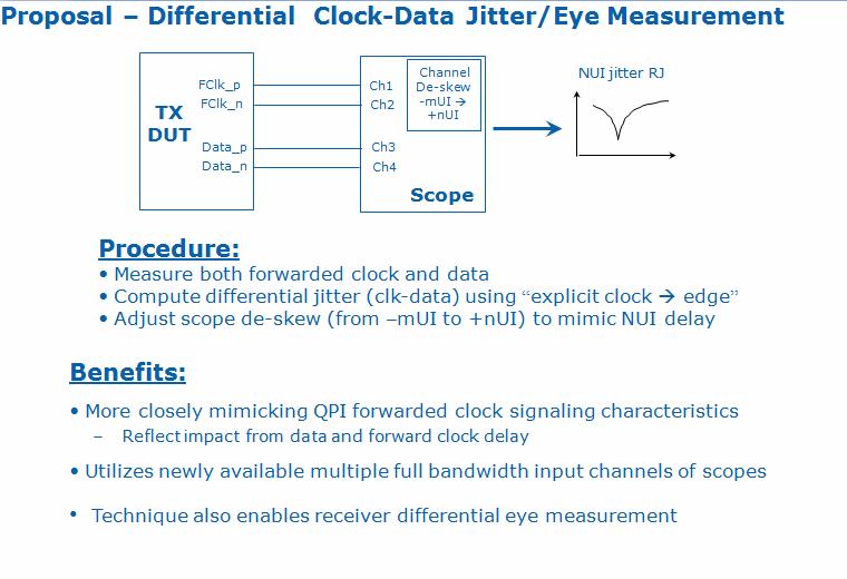
20 What is QPI QPI Quick Path Interconnect Replacement for the old Front Side Bus 20 Lane DC coupled Link 1 Double pumped forwarded clock link E.g. 3.2Ghz clock for 6.4Gb/s operation Differential point to point Common reference clock for 2 ends of the link The agents at the 2 ends are peers Most implementations have DLL based Rx clocking and not a clean up PLL based arch. data clk UI and Jitter definition UI definition UI Jitter definition UI-UI Jitter definition N UI Jitter definition Accumulated jitter over NUI Very important factor in true forwarded clock links Gives QPI links the ability to track/reject power supply resonance induced jitter
21 Benefit of Forwarded Clock System Fwd clk td H(s) Jitter characteristics H(s)(1-e -std ) data H(s) 2.5 (1-e -std ) Plotted as Function of Delay td td=1.4ns Minimizing td crucial 1 PCIe gen3 CDR min 3dB BW 10MHz 0.5 jitter attenuated td=780ps 0 td=156ps 1.00E E E E+10 f=1/td Observations: Illustration of jitter reduction from forwarded clock signaling First zero at f=1/td for 156ps delay, 6.4GHz Jitter reduction effect reduces as delay increases
22 Typical method used for measurement in our Labs Clock like waveform from a single lane captured with a real time scope Wave for fed to a tool internally written in matlab Uses tail fit method to extract Rjand uses that to get DJ(δδ) Limitations The numbers of UIs that the tool can handle is limited That limitation leads to decimation headaches QPI GUI
23


24 Specs to be met at Package Pin WF de-embedded back to that point
Advanced Jitter Analysis with Real-Time Oscilloscopes
 with Real-Time Oscilloscopes August 10, 2016 Min-Jie Chong Product Manager Agenda Review of Jitter Decomposition Assumptions and Limitations Spectral vs. Tail Fit Method with Crosstalk Removal Tool Scope
5 GT/s and 8 GT/s PCIe Compared
 5 GT/s and 8 GT/s PCIe Compared Bent Hessen-Schmidt SyntheSys Research, Inc. Copyright 2008, PCI-SIG, All Rights Reserved 1 Disclaimer The material included in this presentation reflects current thinking
Jitter Basics Lab Using SDAIII & Jitter Sim
 Jitter Basics Lab Using SDAIII & Jitter Sim TUTORIAL August 1, 2012 Summary JitterSim is a math function, enabled by the Serial Data Analysis option, which allows various aspects of jitter to be simulated
Keysight Technologies EZJIT Plus Jitter Analysis Software for Infiniium Oscilloscopes. Data Sheet
 Keysight Technologies EZJIT Plus Jitter Analysis Software for Infiniium Oscilloscopes Data Sheet 02 Keysight EZJIT Plus Jitter Analysis Software for Infiniium Oscilloscopes - Data Sheet Table of Contents
Analyzing Digital Jitter and its Components
 2004 High-Speed Digital Design Seminar Presentation 4 Analyzing Digital Jitter and its Components Analyzing Digital Jitter and its Components Copyright 2004 Agilent Technologies, Inc. Agenda Jitter Overview
High-Speed Jitter Testing of XFP Transceivers
 White Paper High-Speed Jitter Testing of XFP Transceivers By Andreas Alpert Abstract Jitter is a key performance factor in high-speed digital transmission systems, such as synchronous optical networks/synchronous
Agilent Technologies EZJIT and EZJIT Plus Jitter Analysis Software for Infiniium Series Oscilloscopes
 Agilent Technologies EZJIT and EZJIT Plus Jitter Analysis Software for Infiniium Series Oscilloscopes Data Sheet Features of the EZJIT Plus software that optimize jitter analysis include: Easy-to-use jitter
On the Modeling and Analysis of Jitter in ATE Using Matlab
 On the Modeling and Analysis of Jitter in ATE Using Matlab Kyung Ki Kim, Jing Huang, Yong-Bin Kim, Fabrizio Lombardi Department of Electrical and Computer Engineering Northeastern University, Boston, MA,
PCI Express 3.0 Characterization, Compliance, and Debug for Signal Integrity Engineers
 PCI Express 3.0 Characterization, Compliance, and Debug for Signal Integrity Engineers - Transmitter Testing - Receiver Testing - Link Equalization Testing David Li Product Marketing Manager High Speed
What the Dual-Dirac Model is and What it is Not
 What the Dual-Dirac Model is and What it is Not Ransom Stephens October, 006 Abstract: The dual-dirac model is a simple tool for estimating total jitter defined at a bit error ratio, TJ(BER), for serial
Serial ATA Gen2 Jitter Tolerance Testing
 Serial ATA Gen2 Jitter Tolerance Testing Abstract Guy Foster SyntheSys Research, Inc. February 21, 2006 SR-TN054 Serial ATA [i] is an increasingly common serial bus technology aimed at disk drive applications.
PCI Express 4.0. Electrical compliance test overview
 PCI Express 4.0 Electrical compliance test overview Agenda PCI Express 4.0 electrical compliance test overview Required test equipment Test procedures: Q&A Transmitter Electrical testing Transmitter Link
Virtex-6 FPGA GTX Transceiver Characterization Report
 Virtex-6 FPGA GTX Transceiver Characterization Report PCI Express 2.0 (2.5 and 5.0 Gb/s) Electrical Standard Xilinx is disclosing this user guide, manual, release note, and/or specification (the Documentation
40 and 100 Gigabit Ethernet Consortium Clause 86 40GBASE-SR4 and 100GBASE-SR10 PMD Test Suite v0.1 Technical Document
 40 and 100 Gigabit Ethernet Consortium Clause 86 40GBASE-SR4 and 100GBASE-SR10 PMD Test Suite v0.1 Technical Document Last Updated: March 26, 2013 10:00am 40 and 100 Gigabit Ethernet Consortium 121 Technology
PCI Express Electrical Basics
 PCI Express Electrical Basics Dean Gonzales Advanced Micro Devices Copyright 2015, PCI-SIG, All Rights Reserved 1 Topics PCI Express Overview Enhancements for 8GT/s Target Channels for the Specification
DisplayPort 1.4 Webinar
 DisplayPort 1.4 Webinar Test Challenges and Solution Yogesh Pai Product Manager - Tektronix 1 Agenda DisplayPort Basics Transmitter Testing Challenges DisplayPort Type-C Updates Receiver Testing Q and
T10 Technical Committee From: Barry Olawsky, HP Date: 13 January 2005 Subject: T10/05-025r1 SFF8470 Crosstalk Study
 To: T10 Technical Committee From: Barry Olawsky, HP (barry.olawsky@hp.com) Date: Subject: T10/ Revision History Revision 0 (5 January 2005) First revision Revision 1 () Second revision Further clarify
Q2 QMS/QFS 16mm Stack Height Final Inch Designs In PCI Express Applications Generation Gbps. Revision Date: February 13, 2009
 Q2 QMS/QFS 16mm Stack Height Final Inch Designs In PCI Express Applications Generation 2 5.0 Gbps Revision Date: February 13, 2009 Copyrights and Trademarks Copyright 2009 Samtec, Inc. Developed in conjunction
Specifying Crosstalk. Adam Healey Agere Systems May 4, 2005
 Specifying Crosstalk Adam Healey Agere Systems May 4, 2005 Proposal Use the power-sum crosstalk (MDNEXT and MDFEXT) limits proposed by D Ambrosia et al. [1] as the normative specification for crosstalk.
EZJIT Plus Jitter Analysis Software for Infiniium Oscilloscopes
 EZJIT Plus Jitter Analysis Software for Infiniium Oscilloscopes Data Sheet EZJIT Plus software includes all of the basic jitter analysis features of EZJIT and adds the following advanced analysis capabilities:
Q Pairs QTE/QSE-DP Final Inch Designs In PCI Express Applications 16 mm Stack Height
 Application Note Q Pairs QTE/QSE-DP Final Inch Designs In PCI Express Applications 16 mm Stack Height Copyrights and Trademarks Copyright 2004 Samtec, Inc. Developed in conjunction with Teraspeed Consulting
RT-Eye PCI Express Compliance Module Methods of Implementation (MOI)
") Technical Reference RT-Eye PCI Express Compliance Module Methods of Implementation (MOI) 071-2041-00 www.tektronix.com Copyright Tektronix. All rights reserved. Licensed software products are owned by
Technical Reference RT-Eye PCI Express Compliance Module Methods of Implementation (MOI) 071-2041-00 www.tektronix.com Copyright Tektronix. All rights reserved. Licensed software products are owned by
RiseUp RU8-DP-DV Series 19mm Stack Height Final Inch Designs in PCI Express Applications. Revision Date: March 18, 2005
 RiseUp RU8-DP-DV Series 19mm Stack Height Final Inch Designs in PCI Express Applications Revision Date: March 18, 2005 Copyrights and Trademarks Copyright 2005 Samtec, Inc. Developed in conjunction with
PCI Express Link Equalization Testing 서동현
 PCI Express Link Equalization 서동현 Application Engineer January 19th, 2016 Agenda Introduction Page 2 Dynamic Link Equalization TX/RX Link Equalization Tests Test Automation RX Stress Signal Calibration
EPSON. Technical Note. Oscillator Jitter and How to Measure It. Introduction. Jitter. Cycle-Cycle Jitter
 1960 E. Grand Ave., 2 nd Floor El Segundo, California 90245 Phone: 310.955.5300 Fax: 310.955.5400 Technical Note Oscillator Jitter and How to Measure It Introduction Jitter is a term that is becoming widely
in Synchronous Ethernet Networks
 Jitter and Wander Measurements in Synchronous Ethernet Networks Andreas Alpert ITSF November 2008 Agenda Introduction ti Synchronous Ethernet Ji d W d A Jitter and Wander Aspects Test Applications in SyncE
Board Design Guidelines for PCI Express Architecture
 Board Design Guidelines for PCI Express Architecture Cliff Lee Staff Engineer Intel Corporation Member, PCI Express Electrical and Card WGs The facts, techniques and applications presented by the following
Enabling MIPI Physical Layer Test
 Enabling MIPI Physical Layer Test High Speed Test and Characterization High Speed Digital Test The Explosion of Functions within Mobile Devices Multiple RF functions GPS Bluetooth WCDMA GSM WLAN FM Multiple
Keysight N5990A DisplayPort Extended Tests Embedded DisplayPort
 Keysight N5990A DisplayPort Extended Tests Embedded DisplayPort Calibration and Test Procedure Descriptions User Guide Notices Keysight Technologies 2018 No part of this manual may be reproduced in any
Successfully negotiating the PCI EXPRESS 2.0 Super Highway Towards Full Compliance
 the PCI EXPRESS 2.0 Super Highway Towards Full Compliance Page 1 Agenda Introduction PCIe 2.0 changes from 1.0a/1.1 Spec 5GT/s Challenges Error Correction Techniques Test tool and fixture changes Agilent
PCI Express 1.0a and 1.1 Add-In Card Transmitter Testing
 Abstract PCI Express 1.0a and 1.1 Add-In Card Transmitter Testing Joan Gibson November 2006 SR-TN062 Add-in cards designed for PCI Express require numerous tests to assure inter-operability with different
An Overview of High-Speed Serial Bus Simulation Technologies
 An Overview of High-Speed Serial Bus Simulation Technologies Asian IBIS Summit, Beijing, China September 11, 27.25.2.15.1.5 -.5 -.1 Arpad Muranyi arpad_muranyi@mentor.com Vladimir Dmitriev-Zdorov -.15
Characterize and Debug Crosstalk Issues with Keysight Crosstalk Analysis App
 Chong Min-Jie Characterize and Debug Crosstalk Issues with Crosstalk Analysis App Page Characterize and Debug Crosstalk Issues with Crosstalk Analysis App Min-Jie Chong HPS Product Manager & Planner Oscilloscope
QPHY-USB3.1-TX-RX. Instruction Manual
 QPHY-USB3.1-TX-RX USB3.1 Serial Data Compliance Software Instruction Manual Revision A November, 2017 Related to version: XStreamDSO 8.5.x.x. QualiPHY 8.5.x.x. 700 Chestnut Ridge Road Chestnut Ridge, NY,
Extending HyperTransport Technology to 8.0 Gb/s in 32-nm SOI-CMOS Processors
 Extending HyperTransport Technology to 8.0 Gb/s in 32-nm SOI-CMOS Processors Bruce Doyle, Alvin Loke, Sanjeev Maheshwari, Charles Wang, Dennis Fischette, Jeffrey Cooper, Sanjeev Aggarwal, Tin Tin Wee,
Effortless Burst Separation
 DDR Debug Toolkit Key Features Read/Write burst separation with a push of a button Simultaneous analysis of four different measurement views View up to 10 eye diagrams with mask testing and eye measurements
Agilent. Master your next PCIe test with the Agilent M8020A High-Performance BERT Application Brief
 Agilent Master your next PCIe test with the Agilent M8020A High-Performance BERT Application Brief 1 Table of Contents Contents Disclaimer... 3 1 Introduction... 4 2 PCI Express Specifications... 4 3 PCI
Serial Link Analysis and PLL Model
 25. July 2007 Serial Link Analysis and PLL Model September 11, 2007 Asian IBIS Summit, Beijing China Huang Chunxing huangchunxing@huawei.com www.huawei.com HUAWEI TECHNOLOGIES Co., Ltd. Agenda High-speed
Virtex-5 FPGA RocketIO GTX Transceiver Characterization Report
 Virtex-5 FPGA RocketIO GTX Transceiver Characterization Report PCI Express 2.0 (5.0 Gb/s) Electrical Gb/s) Standard Electrical Standard [optional] [optional] Xilinx is disclosing this user guide, manual,
DisplayPort Testing Challenges
 DisplayPort Testing Challenges U N Vasudev May 6 th 2013 Agenda DisplayPort Overview DisplayPort 1.2 updates DisplayPort 1.2 Transmitter Testing What s New: T2, TP3, TP3EQ Physical Layer Test Overview
Agilent N5393C PCI Express Electrical Performance and Compliance Software Release Notes
 Agilent N5393C PCI Express Electrical Performance and Compliance Software Release Notes Agilent N5393C Software Version 03.34 Released Date: 19 May 2014 File Name: SetupInfPCIExpress0334.exe Improved algorithm
PCI Express 3.0CEM Stressed Eye Calibration and Receiver Testing
 PCI Express 3.0CEM Stressed Eye Calibration and Receiver Testing Methods of Implementation using Tektronix BERTScope BSA85C Analyzer, CR125A Clock Recovery, DPP125B De-Emphasis Processor, and Series 70000
Tektronix Innovation Forum
 Tektronix Innovation Forum Enabling Innovation in the Digital Age DisplayPort 1.2 Spec Updates and overview of Physical layer conformance testing Presenter: John Calvin DisplayPort 1.2 Spec Updates Agenda
BERTScope Bit Error Rate Testers Jitter Map Under the Hood A New Methodology for Jitter Separation
 BERTScope Bit Error Rate Testers Jitter Map Under the Hood A New Methodology for Jitter Separation Application Note Abstract Jitter Map is a capability on the BERTScope that uses BER measurements tomeasure
Proposal for modeling advanced SERDES
 Proposal for modeling advanced SERDES IBM, Cadence June 2006 1 CADENCE DESIGN SYSTEMS, INC. Presenters, Contributors Presenters / Contributors 1. Joe Abler IBM Systems & Technology Group High Speed Serial
QPairs QTE/QSE-DP Multi-connector Stack Designs In PCI Express Applications 16 mm Connector Stack Height REVISION DATE: OCTOBER 13, 2004
 Application Note QPairs QTE/QSE-DP Multi-connector Stack Designs In PCI Express Applications 16 mm Connector Stack Height REVISION DATE: OCTOBER 13, 2004 Copyrights and Trademarks Copyright 2004 Samtec,
PCIe Certification Guide for i.mx 6Dual/6Quad and i.mx 6Solo/6DualLite
 Freescale Semiconductor Document Number: AN4784 Rev. 0, 10/2013 PCIe Certification Guide for i.mx 6Dual/6Quad and i.mx 6Solo/6DualLite This document provides a description of procedures, tools, and criteria
Raj Kumar Nagpal, R&D Manager Synopsys. Enabling Higher Data Rates and Variety of Channels with MIPI D-PHY
 Raj Kumar Nagpal, R&D Manager Enabling Higher Data Rates and Variety of Channels with MIPI D-PHY Agenda Design motivation MIPI D-PHY evolution Summary of MIPI D-PHY specification MIPI channel evolution
IBIS-AMI Model Simulations Over Six EDA Platforms
 IBIS-AMI Model Simulations Over Six EDA Platforms Romi Mayder, romi.mayder@xilinx.com Ivan Madrigal, ivan.madrigal@xilinx.com Brandon Jiao, brandon.jiao@xilinx.com Hongtao Zhang, hongtao.zhang@xilinx.com
COMPLIANCE STATEMENT
 COMPLIANCE STATEMENT Specification Specification name: PCIE-BASE-REV4.-CC-REFCLK Specification title: Common-clock Refclk Evaluation for PCIe v4. BASE (v1.) Specification owner: JitterLabs Device Under
GIGABIT ETHERNET CONSORTIUM
 GIGABIT ETHERNET CONSORTIUM Clause 38 Optical PMD Test Suite Version 0.7 Technical Document Last Updated: August 19, 2008 11:30 AM Gigabit Ethernet Consortium 121 Technology Drive, Suite 2 Durham, NH 03824
USB Type-C Active Cable ECN
 USB Type-C Active Cable ECN Christine Krause Active Cable WG Chair (Sponsored by Intel Corporation) USB Developer Days 2017 Taipei, Taiwan October 24 25, 2017 1 Introduction Scope Requirements for active
Debugging and Compliance Testing of Serial Designs
 Debugging and Compliance Testing of Serial Designs Agenda High Speed Serial Data Fundamentals Introduction Architecture and common elements Performance requirements Filtering/Equalization Probing/Signal
High-speed I/O test: The ATE paradigm must change
 High-speed I/O test: The ATE paradigm must change 2005 VLSI Test Symposium Session 4C Burnie West May 2005 Outline The brave new world Test methodology PHY testing Functional testing ATE specifications
SAS-2 Zero-Length Test Load Characterization (07-013r7) Barry Olawsky Hewlett Packard (8/2/2007)
 Barry Olawsky Hewlett Packard (8/2/2007)") SAS-2 Zero-Length Test Load Characterization (07-013r7) Barry Olawsky Hewlett Packard (8/2/2007) 07-013r7 SAS-2 Zero-Length Test Load Characterization 1 Zero-Length Test Load Provides ideal connection
SAS-2 Zero-Length Test Load Characterization (07-013r7) Barry Olawsky Hewlett Packard (8/2/2007) 07-013r7 SAS-2 Zero-Length Test Load Characterization 1 Zero-Length Test Load Provides ideal connection
SEAM-RA/SEAF-RA Series Final Inch Designs in PCI Express Applications Generation GT/s
 SEAM-RA/SEAF-RA Series Final Inch Designs in PCI Express Applications Generation 3-8.0 GT/s Copyrights and Trademarks Copyright 2011 Samtec, Inc. Developed in conjunction with Teraspeed Consulting Group
PCI Express 4.0 Test Solution
 PCI Express 4.0 Test Solution Key Features PCIe Gen4 CEM compliance testing: Transmitter preset and signal quality Transmitter link equalization Receiver test calibration Receiver jitter tolerance Fully
Understanding and Performing Precise Jitter Analysis
 Understanding and Performing Precise Jitter Analysis Rapidly ascending clock rates and tighter timing margins are creating a need for jitter and timing measurements in mainstream circuits Introduction
Cost Effective Solution for Receiver Characterization
 12.5 Gb/s Programmable Pattern Generator Cost Effective Solution for Receiver Characterization Product Highlights 24Mb pattern memory supports virtually any pattern Integrated two tap de-emphasis Fully
Agilent N5393C PCI Express Automated Test Application
 Agilent N5393C PCI Express Automated Test Application Compliance Testing Methods of Implementation Agilent Technologies Notices Agilent Technologies, Inc. 2004-2010 No part of this manual may be reproduced
Compliance test method and detailed spec for -USB3.0. Tektronix Korea YJ.PARK
 Compliance test method and detailed spec for -USB3.0 Tektronix Korea YJ.PARK Differences from USB2.0 High-Speed 480MT/s No-SSC 2 wires for signaling Tx and Rx use the same wire 1 bi-directional link DC
USB 3.0 Receiver Compliance Testing
 USB 3.0 Receiver Compliance Testing Methods of Implementation Using Tektronix BERTScope BSA85C Analyzer, CR125A Clock Recovery, DPP125B Digital De-Emphasis Processor, Instrument Switch, and DSA/DSO/MSO71254B
Application Note. PCIE-RA Series Final Inch Designs in PCI Express Applications Generation GT/s
 PCIE-RA Series Final Inch Designs in PCI Express Applications Generation 3-8.0 GT/s Copyrights and Trademarks Copyright 2012, Inc. COPYRIGHTS, TRADEMARKS, and PATENTS Final Inch is a trademark of, Inc.
R&S RTO-K81, R&S RTP-K81 PCIe Compliance Test Test Procedures
 PCIe Compliance Test Test Procedures (=QFñ2) 1333229902 Test Procedures Version 03 This manual describes the PCIe compliance test procedures with the following options: R&S RTO-K81 (1326.0920.02) - PCIe
ASNT_MUX64 64Gbps 2:1 Multiplexer
 ASNT_MUX64 64Gbps 2:1 Multiplexer 105ps data phase shift capability for both data inputs VCO s from 20GHz to 32.1GHz User selectable clock divide by 2 to 512 sync output for scope triggering 17ps Rise/Fall
PCI Express Rx-Tx-Protocol Solutions
 PCI Express Rx-Tx-Protocol Solutions Customer Presentation December 13, 2013 Agenda PCIe Gen4 Update PCIe Gen3 Overview PCIe Gen3 Tx Solutions Tx Demo PCIe Gen3 Rx Solutions Rx Demo PCIe Gen3 Protocol
PCIe 3.0 Compliance Testing Dan Froelich Serial Enabling Workgroup Co-Chair
 PCIe 3.0 Compliance Testing Dan Froelich Serial Enabling Workgroup Co-Chair Copyright 2015, PCI-SIG, All Rights Reserved 1 Agenda PCIe Compliance Program Status PCIe Compliance Process Compliance Test
Application Note. PCIE-EM Series Final Inch Designs in PCI Express Applications Generation GT/s
 PCIE-EM Series Final Inch Designs in PCI Express Applications Generation 3-8.0 GT/s Copyrights and Trademarks Copyright 2015, Inc. COPYRIGHTS, TRADEMARKS, and PATENTS Final Inch is a trademark of, Inc.
100G SWDM4 MSA Technical Specifications Optical Specifications
 100G SWDM4 MSA Technical Specifications Specifications Participants Editor David Lewis, LUMENTUM The following companies were members of the SWDM MSA at the release of this specification: Company Commscope
40 AND 100 GIGABIT ETHERNET TESTING SERVICE
 40 AND 100 GIGABIT ETHERNET TESTING SERVICE Clause 95 100GBASE-SR4 PMD Test Plan Version 1.1 Technical Document Last Updated: January 23, 2018 40 and 100 Gigabit Ethernet Testing Service 21 Madbury Road,
Virtex-6 FPGA GTX Transceiver OTU1 Electrical Interface
 Virtex-6 FPGA GTX Transceiver OTU1 Electrical Interface Characterization Report Xilinx is disclosing this user guide, manual, release note, and/or specification (the "Documentation") to you solely for
Reference. Menu Overview. Functions Common to Generator (TX) and Analyzer (RX) AC Power. Selecting 115 VAC or 230 VAC Operation
 and Analyzer (RX) AC Power. Selecting 115 VAC or 230 VAC Operation") Menu Overview A wide range of "auxiliary" setup functions is provided in the GB1400 Generator and Analyzer Menu systems. To enter the Generator or Analyzer Menu system, simply press the instrument's F1
Menu Overview A wide range of "auxiliary" setup functions is provided in the GB1400 Generator and Analyzer Menu systems. To enter the Generator or Analyzer Menu system, simply press the instrument's F1
Agilent N5393B PCI Express Automated Test Application
 Agilent N5393B PCI Express Automated Test Application Compliance Testing Methods of Implementation Agilent Technologies Notices Agilent Technologies, Inc. 2004-2009 No part of this manual may be reproduced
Agilent Technologies N5393A PCI Express Electrical Performance Validation and Compliance Software for Infiniium 54855A or Series Oscilloscopes
 Agilent Technologies N5393A PCI Express Electrical Performance Validation and Compliance Software for Infiniium 54855A or 80000 Series Oscilloscopes Data Sheet Verify and debug your PCI Express designs
High Speed Design Testing Solutions
 High Speed Design Testing Solutions - Advanced Tools for Compliance, Characterization and Debug name title Agenda High-Speed Serial Test Challenges High-Speed Serial Test Simplified - Characterization
UNH IOL SERIAL ATTACHED SCSI (SAS) CONSORTIUM
 CONSORTIUM") UNH IOL SERIAL ATTACHED SCSI (SAS) CONSORTIUM SAS 3.0 Receiver Physical Layer Test Suite Version 1.00 Technical Document Last Updated: September 29, 2014 UNH IOL SAS Consortium 121 Technology Drive, Suite
UNH IOL SERIAL ATTACHED SCSI (SAS) CONSORTIUM SAS 3.0 Receiver Physical Layer Test Suite Version 1.00 Technical Document Last Updated: September 29, 2014 UNH IOL SAS Consortium 121 Technology Drive, Suite
Automotive Ethernet BroadR-Reach
 Automotive Ethernet BroadR-Reach Agilent PHY Compliance Solutions 1 Last update 2013/07/25 (YS) Agenda BroadR-Reach Overview Transmitter Testing Link Segment Testing 2 BroadR-Reach Applications 3 Connectivity
SONET OC-12 JITTER MEASUREMENT
 SONET OC-12 JITTER MEASUREMENT JITTER GENERATION Jitter Generation Definition Bellcore TR-NWT-000499 (Issue 4), section 7.3.3 "Jitter generation is the process whereby jitter appears at the output port
Serial ATA International Organization
 SyntheSys Research, Inc. Serial ATA International Organization Version 1.0 June 4, 2009 Serial ATA Interoperability Program Revision 1.4 SyntheSys Research, Inc. MOI for RSG Tests (using BERTScope 7500B
Simulation Results for 10 Gb/s Duobinary Signaling
 Simulation Results for 10 Gb/s Duobinary Signaling Populating the Signaling Ad Hoc Spreadsheet IEEE 802.ap Task Force Atlanta March 15-17, 2005 802.AP Backplane Ethernet Contributors Vitesse Majid Barazande-Pour
The Jitter-Noise Duality and Anatomy of an Eye Diagram
 DesignCon 2014 The Jitter-Noise Duality and Anatomy of an Eye Diagram Vladimir Dmitriev-Zdorov, Mentor Graphics vladimir_dmitriev-zdorov@mentor.com Martin T. Miller, Teledyne LeCroy marty.miller@teledynelecroy.com
Characterizing Your PLL-based Designs To Manage System Jitter. Agilent Technologies
 Characterizing Your PLL-based Designs To Manage System Jitter Rob Sleigh Greg D. Le Cheminant Agilent Technologies Copyright 2008 Agilent Technologies Page 1 Outline A review of digital communications
JitKit. Operator's Manual
 JitKit Operator's Manual March, 2011 LeCroy Corporation 700 Chestnut Ridge Road Chestnut Ridge, NY, 10977-6499 Tel: (845) 578-6020, Fax: (845) 578 5985 Internet: www.lecroy.com 2011 by LeCroy Corporation.
QPHY-PCIE (Gen1 and Gen2) Operator s Manual
 Operator s Manual") QPHY-PCIE (Gen1 and Gen2) Operator s Manual Revision B November, 2017 Relating to: XStreamDSO Version 8.5.x.x QualiPHY Version 8.5.x.x 700 Chestnut Ridge Road Chestnut Ridge, NY, 10977-6499 Tel: (845)
QPHY-PCIE (Gen1 and Gen2) Operator s Manual Revision B November, 2017 Relating to: XStreamDSO Version 8.5.x.x QualiPHY Version 8.5.x.x 700 Chestnut Ridge Road Chestnut Ridge, NY, 10977-6499 Tel: (845)
PCIEC PCI Express Jumper High Speed Designs in PCI Express Applications Generation GT/s
 PCIEC PCI Express Jumper High Speed Designs in PCI Express Applications Generation 3-8.0 GT/s Mated with PCIE-RA Series PCB Connectors Copyrights and Trademarks Copyright 2015, Inc. COPYRIGHTS, TRADEMARKS,
AN 608: HST Jitter and BER Estimator Tool for Stratix IV GX and GT Devices
 AN 608: HST Jitter and BER Estimator Tool or Stratix IV GX and GT Devices July 2010 AN-608-1.0 The high-speed communication link design toolkit (HST) jitter and bit error rate (BER) estimator tool is a
An Innovative Simulation Workflow for Debugging High-Speed Digital Designs using Jitter Separation
 An Innovative Simulation Workflow for Debugging High-Speed Digital Designs using Jitter Separation C. Chastang, A. Amédéo V. Poisson, P. Grison, F. Demuynck C. Gautier, F. Costa Thales Communications &
Product Information Sheet PDA14 2 Channel, 14-Bit Waveform Digitizer APPLICATIONS FEATURES OVERVIEW
 Product Information Sheet PDA 2 Channel, -Bit Waveform Digitizer FEATURES 2 Channels at up to 100 MHz Sample Rate Bits of Resolution Bandwidth from DC-50 MHz 512 Megabytes of On-Board Memory 500 MB/s Transfer
PCIe 4.0 Physical Layer Transmitter and Receiver Testing
 PCIe 4.0 Physical Layer Transmitter and Receiver Testing April 2017 Rick Eads PCI Express Solutions Planner Page Agenda PCIe 4.0 Ecosystem and Timeline PCIe 4.0 TX Testing and Tools PCIe U.2 Testing RX
PCI Express TM Architecture. PHY Electrical Test Considerations Revision 1.1
 PCI Express TM Architecture PHY Electrical Test Considerations Revision 1.1 February 2007 i PHY ELECTRICAL TEST CONSIDERATIONS, REVISION 1.1 REVISION REVISION HISTORY DATE 1.0 Initial Release. 4/26/2004
Agilent Technologies Advanced Signal Integrity
 Agilent Technologies Advanced Signal Integrity Measurements for Next Generation High Speed Serial Standards Last Update 2012/04/24 (YS) Appendix VNA or TDR Scope? ENA Option TDR Overview USB 3.0 Cable/Connector
Keysight N4880A Reference Clock Multiplier
 Keysight Reference Clock Multiplier Achieve Accurate and Simplified Receiver Test for PCI Express, SD UHS-II Host and MIPI M-PHY Devices Data Sheet Multiply reference clocks from 19.2 to 100 MHz to provide
Crosstalk Analysis Application
 Crosstalk Analysis Application User's Guide Notices Keysight Technologies, Inc. 2009-2017 No part of this manual may be reproduced in any form or by any means (including electronic storage and retrieval
Gain and Equalization Adaptation to Optimize the Vertical Eye Opening in a Wireline Receiver. D. Dunwell and A. Chan Carusone University of Toronto
 Gain and Equalization Adaptation to Optimize the Vertical Eye Opening in a Wireline Receiver D. Dunwell and A. Chan Carusone University of Toronto Analog Front End Adaptation Analog Front-End (AFE) Digital
Ethernet SFF-8431 SFP+ SFF-8635 QSFP+ Compliance and Debug Testing. Anshuman Bhat Product Manager
 Ethernet SFF-8431 SFP+ SFF-8635 QSFP+ Compliance and Debug Testing Anshuman Bhat Product Manager Agenda QSFP+ SFP+ Technology Overview Testing challenges Performing TWDPc Measurements Solution for Debug
ADS USB 3.1 Compliance Test Bench
 ADS 2016.01 USB 3.1 Compliance Test Bench Notices Keysight Technologies, Inc. 1983-2016 1400 Fountaingrove Pkwy., Santa Rosa, CA 95403-1738, United States All rights reserved. No part of this documentation
LVDS applications, testing, and performance evaluation expand.
 Stephen Kempainen, National Semiconductor Low Voltage Differential Signaling (LVDS), Part 2 LVDS applications, testing, and performance evaluation expand. Buses and Backplanes D Multi-drop D LVDS is a
Keysight Technologies
 Keysight Technologies How to Pass Receiver Test According to PCI Express 3.0 CEM Specification with Add-In Cards and Motherboards Application Note Table of Contents 1. Introduction...3 2. Overview of the
SHFP-GE-B Gb/s BiDi SFP Transceiver Hot Pluggable, Simplex LC/SC, +3.3V, Single mode, 80km, 0~70 C 1490/1550nm DFB/PIN
 SHFP-GE-B80 1.25Gb/s BiDi SFP Transceiver Hot Pluggable, Simplex LC/SC, +3.3V, Single mode, 80km, 0~70 C 1490/1550nm DFB/PIN SHFP-GE-B80 high performance, cost-effective 1.25G BiDi SFP transceiver complies
SB Gb/s 1-Channel Programmable BERT. Data Sheet
 SB1601 14.5 Gb/s 1-Channel Programmable BERT Data Sheet The BERT Re-imagined Complete single channel BERT system 14.5 Gb/s with excellent signal fidelity Plug & play error detection with built-in CDR Flexible,