rooms Conference Room Mac Quickstart Guide
|
|
|
- Daniel Byrd
- 5 years ago
- Views:
Transcription

1 rooms Conference Room Mac Quickstart Guide
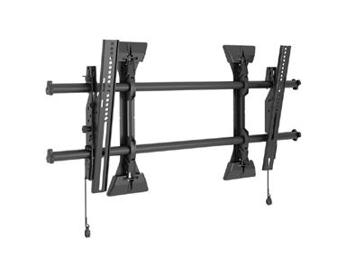
2 WARNING: IMPROPER INSTALLATION CAN LEAD TO MOUNT FALLING CAUSING SEVERE PERSONAL INJURY OR DAMAGE TO EQUIPMENT! It is the installers responsibility to make certain the structure to which the accessory is being attached is capable of supporting five times the combined weight of accessory and mount, not to exceed weight capacities listed in Table 1 Table 1: Chief FCAV1U Warning Weight Capacity When Attached to FCAV1U WARNING: LTM1U: Max Weight Allowed 150lbs (68.0 kg) XTM1U: Max Weight Allowed 150lbs (68.0 kg) Use this accessory only for its intended use as described in these instructions. Do not use attachments not recommended by the manufacturer. WARNING: Never operate this accessory if it is damaged. Return the accessory to a service center for examination and repair. WARNING: Do not use this product outdoors. IMPORTANT! : The FCAV1U accessory is designed to be mounted to: a bare 8 concrete or 8 x8 x16 concrete block wall, or a 2 x 4 wood studs wall covered by drywall with maximum thickness of 5/8 : MSM1U/MTM1U/MTMP1U: Wood studs must be 16 on center; LSM1U/LTM1U: Wood studs may be 16 or 24 on center; XSM1U/XTM1U: Wood studs may be 24 or 32 on center. NOTE: Accessory is intended to be used with the following Chief mounting systems (not included): 2
3 Tools Required For Install tape measure, drill & drill bits, stud finder, socket set, screwdrivers (regular & philips), utility knife, drywall saw, pencil, blue painter tape, small shop vac, level Tape Measure Drill and Bits Stud Finder Imperial Socket Set Screw Drivers Utility Knife Drywall Saw Painters Tape Pencil Shop Vac Level 3


4 Parts List Huddle Room Mac 1A A Mac Mini 9.7 Inch ipad Aver Cam340 MXL AC404 Microphones X2 Heckler Design Meeting Room Console Tryten Wall Mount Logitech Wireless Keyboard w/ touchpad Pulse Eight USB to HDMI CEC control adapter Lindy HDMI NON- CEC Adapter Kramer 6 Flexible High-Speed HDMI cable Heckler Design Camera Mount Local and Remote IOGear USB Extender 50ft CAT6 cable Star Tech USB to Lightning 3M 6ft CAT6 cable APC AC Power strip w/7 Outlet Cable ties Cable Tie Mount pads Grainger #6 zinc wood screws TechFlex Cable Cover Split Loom 3M 1 x 3 Re-closable fasteners clear /8 Toggle Bolts X4 Chief FCAV1U Accesory Arms Chief LTM1U Wall Mount 55 Inch Display Brush Plate x 2 4
5 Locate Mounting Site If you already have a display you can skip to page 9 Lead Tech 1 Role A: Measure wall where display will be installed on the wall and layout device locations Find center of table in room and mark that as your center line (CL) on the wall Use blue painters tape ONLY and mark on the tape with pencil Measure 64.5 from floor to CL and mark center point of display location. Outline the 65 TV location with blue painters tape on the wall The blue tape s OUTER edges represent the edge of the TV You will not mount anything touching this blue tape line Prevents protruding items from behind TV 48 from floor to bottom of TV 81 from floor to top of TV 28.5 from center line to sides of diplay ( CL on diagram ) Mount the sound bar so the base is 1.5 inches above the top of the monitor. Edge of Display Blue Tape Outline 81 Top of Display 72 Brush Plate Center of Display CL 48 Bottom of Display Mount camera so the top is flush with the base of the monitor 12 Brush Plate Floor Be sure to center the display position with the center of the conference table in the room 5
6 Installing the Chief FCAV1U pull out arms to a stud wall 1. Determine the center of the TV screen, and where it should be located on the wall. 2. Locate the closest stud to the left and right of the selected location using a stud finder. NOTE: If the screen area lies over a stud, use that stud and the stud to either the left or right of it. 3. Line up the diamond cutouts on FCAV1U pullout (A) with center of screen marking to determine vertical center. (See Figure 1) 4. Measure up 8 from the center point (by hooking tape measure in slots on front of FCAV1U) to mark location of the upper mounting slots. (Figure 1) Figure 1. Figure Using a level, mark the wall on each stud to attach the accessory through the upper mounting slots. (See Figure 2) 6
7 Installing the Chief FCAV1U pull out arms to a stud wall, continued 6. Drill one 1/2 hole in each stud for the upper mounting point of the FCAV1U for 3/8 zip toggle NOTE: The slotted washers have been included to help make the installation easier. Wait to place the slotted washer AFTER the Fusion pullouts are hanging on the partially installed toggle bolts. (See Steps 7-10) 7. Partially install two 3/8 x 2-1/2 flanged bolts (B) into pilot holes but do not tighten to wall. 8. Hang both Fusion pullouts (A), aligning upper mounting slots over the bolts and adjust side-to-side for proper location. 9. Place one slotted washer (D) over each flanged bolt. (See Figure 2) 10. Tighten bolts to secure accessory (A) to wall at upper mounting slots. 11. Mark the attachment points for the lower mounting slots, making sure the attachment points are located on the studs. (See Figure 2) 12. Drill 1/2 holes at markings for lower mounting holes. (See Figure 2) 13. Use two 3/8 x 2-1/2 flanged bolts (B) and two 3/8 slotted washers (D) to attach both pullouts (A) to the wall through the lower mounting holes. (See Figure 2) 14. Proceed to Attaching Mounting System section. Figure 2 Center of screen 8 Vertical center of accessory. 7
8 Attaching the Mounting System LTM1U 1. Attach top of mounting system (not included) to top of FCAV1U accessories using two 5/16-18 x 1/2 button head cap screws (G) and two 5/16 washers (J) in each top mounting slot Attach bottom of mounting system to bottom of FCAV1U accessories using two 1/4-20 x 1/2 socket head cap screws (F) and two 1/4 washers (H) in each bottom mounting slot. (See Figure 4) 8
9 Front Wall Mount the sound bar so the base is 1.5 inches above the top of the monitor. Edge of Display Blue Tape Outline 81 Top of Display 72 Brush Plate Center of Display CL 48 Bottom of Display Mount camera so the top is flush with the base of the monitor 12 Brush Plate Floor 9
10 Front Wall Device installation 1. Install the TV s brush plate wall entry for the cable pathway behind TV to lower wall. Use wall stud finder to avoid and locate any studs a: Goal = 12 inches above finished floor to the top of the lower plate and 5-6 inches below the top edge of the display for the upper brush plate b: Use brush plate as cutout template, mark with pencil and cutout drywall and screw in upper and lower plates. 2. Install Optiplex wall mount using provides drywall anchors a: Locate the Optiplex wall mount to the side of the TV, upper corner, opposite of the door b: Mount it 6 away from the blue tape TV outline s INNER edge. c: Slide the Optiple inside the Optiplex wall mount with connections facing out for future service or support d: Attach security lock and loop the key around the top slot with a cable tie 3. Install Lindy adaptor into the DP to HDMI adapter cable. 4. Mount remote IOGEAR USB Local Extender directly below the Mac Mini a: Use 2 cable tie mount pads, 2 small drywall screws, and 2 zip ties on extender Rx 5. Install the Pulse Eight CEC adaptor below USB extender remote unit using the cable tie mount pads and drywall screws and zip ties 6. Mount power strip horizontally 6 below display edge where there is adequate room to reach and plug cords in and out as needed for service. 7. Using provided cable ties and supports neatly dress the cabling as needed to make a neat and professional appearance, this includes HDMI, USB, data and power cables 8. Install the display on the wall mount 9. Mount the web camera wall mount to the wall using the provides wall anchors, below TV, or rested on top of TV (depending on room) 10
11 Lead Tech 2 Role B: 1. Inspect and un-box all the delivered items for the project. Identify all items against the packing slip, note any damage or missing items immediately. 2. Sort devices and cables by location, front wall and table and refer to drawing if necessary 3. Un-box the tables devices, microphones, USB local extenders, ipad, meeting console, keyboard and layout for placement a: Place the items near where they need to be installed b: Flatten boxes and place them along the side wall nearest the door 4. Prepare cable pull from the front wall to the table with Tech A. 5. Mount IOGEAR USB Extender Remote under table + Plug in 2 USB mics and dress cable neatly and secure under table. a: Use 2 cable tie mount Pads, 2 small wood screws, and 2 ties to mount the USB Local extender TX 6. Install display on wall mount and also connect power and HDMI cable 7. Place ipad in the ipad meeting console at the table refer to the instruction with the Heckler device for mounting details 8. Make all the connections accordingly and dress in cable as you go to keep a neat and serviceable installation. 11


12 Table Top and Below Table Always refer to each individual product installation guide to insure proper installation and functionality. Install the 9.7 inch ipad into the Heckler Design Meeting Room Console H487BG. (Refer to the assembly instructions provided with the Meeting Room Console Included with the Heckler part) Insert the ipad Lightning charging cable into the ipad and plug into the power. From the IOGEAR USB extender on the under side through the table opening and connected to the MXL Mics. Mount the IOGEAR USB extender on the under side of the table using the 3M recloseable fastners. Connect the two MXL AC404 USB Boundary Microphone to the IOGEAR USB local extender using the supplied USB cable to USB ports 1 and 2 respectively to the unit below the table. Plug the IOGEAR USB Extender into the outlet below the table. 12

13 Connection Diagram Always refer to each individual product installation guide to insure proper installation and functionality. Above the Display 30 Sound Bar 29 Below the Table Table Top 2 ipad Behind the Display CPU * Ethernet DP HDMI USB Audio 1 Meeting Console 5 To USB camera A Below display 28A A USB Camera 12 Local Wireless Keyboard 7 Mic 1 Remote Mic To display One HDMI Input #1 7 Port Hub Mic 3 Mic 4 Data To display Two HDMI Input #1 Mic 5 Mic 6 Ethernet HDMI USB Power Audio * insert Logitech Bluetooth dongle into USB port 4 Mic 7 13
14 Support Process Support Ticket means a notification by a customer advising Zoom of a perceived issue, or question concerning the service. Report support tickets to Zoom by: 1. Online submission via 2. Chat live with our support team 3. Phone dial-in US: ext 2 or ext 2 AU: ext 2 UK: ext 2 or ext 2 14
15 Notes 15
16
rooms Assembly Instructions Huddle Room Mac For Aver CAM340, Aver VB342 & Logitech Meetup Systems
 rooms Assembly Instructions Huddle Room Mac For Aver CAM340, Aver VB342 & Logitech Meetup Systems Tools Required For Install Tape measure, drill & drill bits, stud finder, socket set, screwdrivers (regular
Motorized Ceiling TV Mount
 Motorized Ceiling TV Mount Instruction Manual SKU: MOUNT-E-FD55 Scan the QR code with your mobile device or follow the link for helpful videos and specifications related to this product. https://vivo-us.com/products/mount-e-fd55
PracticeWire Installation Manual
 PracticeWire Installation Manual Version 5.0 August 28 th, 2013 PCM Help Desk 1-877-233-9114 Page 1 Table of Contents System Overview 3 Tool List 4 Installation Guide Site Notification 5 Install Universal
INSTALLATION INSTRUCTIONS Version 2.4
 INSTALLATION INSTRUCTIONS Version 2.4 11/12/2012 Patient Point, LLC 8230 Montgomery Road, Suite 300 Cincinnati, Ohio 45236 1-800-287-0908 TABLE OF CONTENTS System Overview 2 Tool List. 3 Installation Process
Waiting Room Network Installation Manual
 Waiting Room Network Installation Manual Version 5.0 March 27 th, 2013 PCM Help Desk 1-877-233-9114 Page 1 Table of Contents System Overview 3 Tool List 4 Installation Guide 5 Site Notification 5 Install
TECHKNOW, INC. Kiosk Order Confirmation System INSTALLATION MANUAL. Revision Date: July 11, 2012 Part # Version 3.2
 document Page 1 of 18 TECHKNOW, INC Kiosk Order Confirmation System INSTALLATION MANUAL Revision Date: July 11, 2012 Part # Version 3.2 Techknow, Inc. 393 Mayfield Road Duncan, SC 29334 www.gotechknow.com
KRONOS INSTALLATION INSTRUCTIONS
 INSTALLATION INSTRUCTIONS TABLE OF CONTENTS ENCLOSURE AND DONGLE ASSEMBLY 1 LIGHTED ENCLOSURES 2-10 2 SLIM ENCLOSURE 11-17 3 WIRED-ETHERNET DONGLE 18-25 4 REAR-OFFSET MOUNT 26-33 5 SIDE-MOUNT 34-41 6 SURFACE
TASER Axon Dock Installation Manual IMPORTANT SAFETY INSTRUCTIONS
 TASER Axon Dock Installation Manual IMPORTANT SAFETY INSTRUCTIONS Read all warnings and instructions. Save these instructions. The most up-to-date warnings and instructions are available at www.taser.com
Innovative Americans, LLC. HD Media Pack Installation Manual
 Innovative Americans, LLC HD Media Pack Installation Manual Please read this manual before you begin! Your installation will be EASIER and SAFER if you take a few moments to read this document!! Proudly
Installation Guide. Interactive Exam Room. Version 1.4
 Installation Guide Interactive Exam Room Version 1.4 Revision Date: August 19 th, 2014 1 Table of Contents Page 3 System Overview 4 Tool List 6 Installation Guide 11 Imaging Instructions 2 System Overview
Flat Panel Static Wall Mount MSP-SS (GSM-210)
") INSTALLATION INSTRUCTIONS Flat Panel Static Wall Mount (GSM-2) The static wall mount fits most 23 to 30 displays. The mount was designed to adapt to the VESA 75mm/0mm, 0mm/0mm, and 200mm/0mm compliant
INSTALLATION INSTRUCTIONS Flat Panel Static Wall Mount (GSM-2) The static wall mount fits most 23 to 30 displays. The mount was designed to adapt to the VESA 75mm/0mm, 0mm/0mm, and 200mm/0mm compliant
TURN-O-MATIC INSTALLATION GUIDE
 TURN-O-MATIC INSTALLATION GUIDE WIRELESS SYSTEM WIRELESS SYSTEM (1) Dispenser (1) Dispenser Mounting Bracket (3) Large Slotted Screw (2) Large Slotted Bolt (2) Nut (1) Display Wall Mount Bracket (1) Wireless
V.I.A. - Monitor Shroud
 V.I.A. - Monitor Shroud NOTE: Installing slatwall above a monitor shroud requires modification of the upper horizontal rail. See V.I.A. Slatwall assembly direction 939502328 for installation process. V.I.A.
Tech Tub Premium: Holds Up to 10 Tablets
 TEC1000 Tech Tub Premium: Holds Up to 10 Tablets Assembly Guide TEC1000_2017_A Check out our other products online at www.copernicused.com For assistance, please contact us: 1-800-267-8494 Email info@copernicused.com
7" Touch Screen Display
 7" Touch Screen Display Installation Guide Contents Minimum Requirements...1 Select a Location...1 Initial Setup...2 Unboxing...2 Installation...3 Prepare the Panel...3 Install the Mounting Plate...3 Mount
FLEXBOX. Installation Guide
 FLEXBOX Installation Guide FLEXBOX 1 Important Safety Instructions WEIGHT LIMIT MAXIMUM WEIGHT 50 LBS. THE STRUCTURE TO WHICH THE BOX IS MOUNTED (CEIL- ING, WALL, TABLE, POLE) MUST BE ABLE TO SUPPORT FIVE
Warning Before Installation. Package Contents EN - 1. Refer to your user's manual for the operating temperature.
 510000221G Warning Before Installation English Power off the Network Camera as soon as smoke or unusual odors are detected. Do not place the Network Camera on unsteady surfaces. Do not insert sharp or
MediaWave MW103 Hospital Digital Network (HDN)
") The MediaWave MW103 replaced the AOpen and the Seneca 1.3 and 2.8 players as the common media players for Patient Point (WRN) Waiting Room, (HDN) Hospital Digital Network, and (PWR) PracticeWire installations.
The MediaWave MW103 replaced the AOpen and the Seneca 1.3 and 2.8 players as the common media players for Patient Point (WRN) Waiting Room, (HDN) Hospital Digital Network, and (PWR) PracticeWire installations.
2x2 Video Wall - NEC P Series Displays - Installation Guide
 2x2 Video Wall - NEC P Series Displays - Installation Guide Materials Checklist Suggested Tools for Installation Supporting Documents NEC P Series LCD (x4) OPS Media Player (x1) OPS Media Player Caddie
Digital Menu Board Wall Mount Installation Instructions
 Digital Menu Board Wall Mount Installation MDSWMB2T4249 MDSWMB3T4249 www.microndisplaysolutions.com Table of Contents Important Safety... 3 Models and Specifications... 4 Package Contents... 5 Step 1 Two(2)
1 Quickstart Guide 1
 1 Quickstart Guide 1 Honey, I m Home! 2 Nucleus at a Glance Instant Video & Audio Calling Privacy & Security Connect with all your loved ones with ease, so home is just The Privacy Camera Shutter, Do Not
DYNAVISION D2 TM INSTALLATION MANUAL
 DYNAVISION D2 TM INSTALLATION MANUAL Rev 12 Dynavision International 8800 Global Way, West Chester, Ohio 45069 USA EMAIL:info@dynavisiond2.com, WEBSITE: www.dynavisiond2.com, FAX: (905) 294-6327 Unpacking
The Nureva Span ideation system. Installation guide. Single panoramic system
 The Nureva Span ideation system Installation guide Single panoramic system Important SAFETY WARNINGS Prior to the installation of this product, the installation instructions should be completely read and
Warning Before Installation. Package Contents EN - 1. Refer to your user s manual for the operating temperature.
 5000020G Warning Before Installation English Power off the Network Camera as soon as smoke or unusual odors are detected. Do not place the Network Camera on unsteady surfaces. Do not insert sharp or tiny
Soundbar Home Theater Speaker System with Bluetooth FAQ (NS-SB316) March 2016
 March 2016") Soundbar Home Theater Speaker System with Bluetooth FAQ (NS-SB316) March 2016 Setup... 2 Question 1: Where can I find mounting and setup instructions?... 2 Question 2: What tools and materials do I need
Soundbar Home Theater Speaker System with Bluetooth FAQ (NS-SB316) March 2016 Setup... 2 Question 1: Where can I find mounting and setup instructions?... 2 Question 2: What tools and materials do I need
ASSEMBLY AND ADJUSTMENT
 EDGE-WALL MONITOR ARM EDGE-WALL Rev A 2/17 Model EDGE-WALL-SLV ASSEMBLY AND ADJUSTMENT EDGE-WALL MONITOR ARM PLEASE REVIEW these instructions before beginning the installation. Check that all parts and
Charging Cabinet Owner s Manual
 by edugear Charging Cabinet Owner s Manual Before using, please read these operating instructions carefully. They contain important advice concerning the use and safety of your Charging Cabinet. The Charging
NAV-1 Lens Support. NAV-2 Lens Support BEFORE YOU BEGIN
 INSTALLATION Lens Support INSTRUCTIONS The Lens Support is compatible with any RPA projector mount. The readily adapts to the following ScreenStar Conversion Lens from Navitar: SSW08 and SST120. LENS SUPPORT
Mounting on the Ceiling Using Flush Mount (Face Down)
") Mounting on the Ceiling Using Flush Mount (Face Down) Installation Guide 2014/02/14 Table of Contents Safety Information... 3 Installation Procedures... 5 Step 1: Drill a Hole on the Ceiling... 5 Step
Mounting on the Ceiling Using Flush Mount (Face Down) Installation Guide 2014/02/14 Table of Contents Safety Information... 3 Installation Procedures... 5 Step 1: Drill a Hole on the Ceiling... 5 Step
LED Lighting Kit For Elara NanoEdge Fixed Frame. Installation Guide. Attention: Read this guide before assembling your screen.
 LED Lighting Kit For Elara NanoEdge Fixed Frame Installation Guide Attention: Read this guide before assembling your screen. INTRODUCTION GETTING STARTED WARNING - Sharp Edges This product may contain
Eaton LCD Lift Flat Panel Display System. Installation Guide
 Eaton LCD Lift Flat Panel Display System Eaton LCD Lift Flat Panel Display System Installation Guide Copyright 2011 Eaton Corporation, Worcester, MA, USA. All rights reserved. Information in this document
Additional Help For additional installation instructions and videos, please visit our website at What s Included
 Model 400, 40, 40 Additional Help For additional installation instructions and videos, please visit our website at www.current-usa.com What s Included Each LOOP Marine Bundle Kit includes: Item A B C D
Extra Large Full Motion TV Mount for Televisions
 8008981 TV Size Range: 47 ~ 84 Maximum Weight Capacity: 60 kg/132 lbs Maximum Mounting Pattern: 800 mm x 600 mm (31.4 x 23.6 ) Distance to the Wall: 5.5-45 cm Extra Large Full Motion TV Mount for 47-84
User s Guide. for RackMac Pro 4U Rack Enclosure for New Mac Pro
 User s Guide for RackMac Pro 4U Rack Enclosure for New Mac Pro Contents 1 Introduction 1 2 RackMac Pro Description 2 External Features Computer Mounting Module 5/64-Inch Hex Wrench Mac Pro Bottom Cover
Parts List: Assembly Instructions:
 My Ride SERVICE MANUAl MyRide ASSEMBLY GUIDE 1.1 ASSEMBLY INSTRUCTIONS ASSEMBLING THE MYRIDE Parts List: Heavy Plate Stabilizer Fin - Right Stabilizer Fin - Left Stabilizer Fin - Large Middle Power Cord
MBE Mounts and Adapters
 MBE Mounts and Adapters MBE Series en Installation Guide MBE Mounts and Adapters Table of Contents en 3 Table of Contents 1 Important safety instructions 4 2 MBE Series Mounts and Adapters 6 2.1 Unpacking
Routing Power and Signal Cables
 10 CHAPTER Revised: May 15, 2013, Parts List Key Part Description Part Number Qty Ctn s 1 Power distribution units 74-4787-01 4 1 2 Speaker cable 37-1062-01 3 1 3 8 m DVI-to-VGA + audio cable 37-0848-01
FE8171V. 3MP 360 Panoramic View Vandal-proof
 FE8171V 3MP 360 Panoramic View Vandal-proof Warning Before Installation English Power off the Network Camera as soon as smoke or unusual odors are detected. Refer to your user's manual for the operating
Warning Before Installation
 Warning Before Installation English Power off the Network Camera as soon as smoke or unusual odors are detected. Refer to your user's manual for the operating temperature. Contact your distributor in the
INSTALLATION INSTRUCTIONS
 INSTALLATION INSTRUCTIONS 19 20 21 01 07 22 23 13 10 12 08 17 18 11 02 14 15 04 03 16 WELCOME PARTS LIST Thank you for purchasing this HealthPoint Technology Cabinet from Humanscale! Before you begin installing
SKYLEVEL INSTALLATION Manual
 SKLEVEL INSTALLATION Manual Southwest Windpower, Inc. 80 West Route 66 Flagstaff, Arizona 8600 USA Phone: 928-779-9463 Fax: 928-779-485 www.skystreamenergy.com June 2009 Southwest Windpower, Inc. All Rights
Wall Mount Accessory Kit for 6 Device Tub
 FTT-ACW / FTT600-W Tech Tub2 Wall Mount Accessory Kit for 6 Device Tub Assembly Guide FTT-ACW / FTT600-W_2017_A Check out our other products online at www.copernicused.com For assistance, please contact
Installing the Cisco MDS 9020 Fabric Switch
 CHAPTER 2 This chapter describes how to install the Cisco MDS 9020 Fabric Switch and its components, and it includes the following information: Pre-Installation, page 2-2 Installing the Switch in a Cabinet
Remote Control Motorized TV Ceiling Mount
 INSTALLATION MANUAL Remote Control Motorized Ceiling Mount CAUTION: DO NOT EXCEED RATED LISTED WEIGHT. SERIOUS INJURY OR PROPERTY DAMAGE MAY OCCUR! DEHA-400E 15 200x200 300x300 400x200 400x400 55" MAX
INSTALLATION INSTRUCTIONS
 2015 F-150 8 MyTouch factory display 360º Vision System (Kit # AVMS-3618) DUE TO THE COMPLEXITY OF THIS KIT PROFESSIONAL INSTALLATION IS REQUIRED CALIBRATION KIT IS REQUIRED FOR FINAL PROGRAMMING -Must
E1135C PDU and Pod Upgrade Procedure
 E4030-90010 Rev. B 12/2003 In this Document... Tools Needed, 2 Contents of the Upgrade Kits, 2 Installation Procedures, 4 Verifying the Power Option of the New PDU, 4 Removing the PDU from the Support
Assembly and Setup Manual
 M-11 Series Copyboard/C-11 Series Captureboard Assembly and Setup Manual This is the installation and assembly manual for the M-11 series/c-11 series. To the Customer Specialized techniques are required
Microscopic Imaging Research Station (MIRS) Assembly Guide. Version 1.0.0
 Assembly Guide. Version 1.0.0") Microscopic Imaging Research Station (MIRS) Assembly Guide www.adsyscontrols.com Adsys Controls, Inc.2012 Version 1.0.0 I. Assembly of the Adsys Controls MIRS system This document explains the assembly
Microscopic Imaging Research Station (MIRS) Assembly Guide www.adsyscontrols.com Adsys Controls, Inc.2012 Version 1.0.0 I. Assembly of the Adsys Controls MIRS system This document explains the assembly
Installation Instructions. for RackMac Pro Computer Mounting Module
 Installation Instructions for RackMac Pro Computer Mounting Module Contents 1 Product Description 1 Computer Mounting Module 5/64-Inch Hex Wrench Mac Pro Bottom Cover Label 2 Mac Pro and Computer Mounting
1. Charging. 2. In-app Setup. 3. Physical Installation. 4. Features. 5. Troubleshooting
 Spotlight Cam Smart Security at Every Corner of Your Home Your new Spotlight Cam lets you extend the Ring of Security around your entire property. Now, you ll always be the first to know when someone s
Smart Security at Every Corner of Your Home
 Spotlight Cam Smart Security at Every Corner of Your Home Your new Spotlight Cam lets you extend the Ring of Security around your entire property. Now, you ll always be the first to know when someone s
Installation guide. Double panoramic system. Triple panoramic system
 The Nureva Span ideation system Installation guide Double panoramic system Triple panoramic system October 2016 1 Important SAFETY WARNINGS Prior to the installation of this product, the installation instructions
Epson SureColor F6070 Setup Guide
 Epson SureColor F6070 Setup Guide 2 Unpacking and Assembling the Printer Read all of these instructions before using your printer. Also be sure to follow all warnings and instructions marked on the printer
Thank you for purchasing one of our products. I hope that the Tech Tub 2
 FTT1000 FTT1000-USB Tech Tub 2-10 Device Setup Assembly Guide FTT1000_FTT1000-USB_2017_D Check out our other products online at www.copernicused.com For assistance, please contact us: 1-800-267-8494 Email
Assembly and Setup Manual
 M-12 Series Copyboard / C-12 Series Captureboard Assembly and Setup Manual This is the installation and assembly manual for the M-12 series Copyboard and C-12 series Captureboard. (The copyboard and/or
The Cisco Wireless IP Phone 8821-EX has not been tested or certified with any accessories for use in Potentially Explosive Atmosphere.
 Supported, page 1 Headsets, page 1 Cisco Wireless IP Phone 8821 Desktop Charger, page 2 Cisco Wireless IP Phone 8821 Multicharger, page 6 Secure the Charger with a Cable Lock, page 10 Supported You can
S Series Stand Assembly Instructions
 S Series Stand Assembly Instructions Contents Stand Base Column Transducer holder Magnetic screwdriver, Allen bit & Phillips bit Grommets (4) Allen wrench 8mm Phillips-head screws (4) 12mm Allen-head screws
CUBE Micro Station User Guide
 CUBE Micro Station User Guide Models TVS10AC CUBE Micro Station - User Guide 1 of 23 How To Use This Guide This User Guide is a resource to provide you guidelines and best practices as you begin using
Installation Instructions
 ENGAGE INFLUENCE OPTIMIZE Installation Instructions Fast Track SA Drive Thru Timing System Effective Date: November 1, 2017 Fast Track SA Installation Instructions Page 2 of 28 Table of Contents 1 INTRODUCTION...
Installation Instructions for the Blue Dot Lock Door Controller
 TM Installation Instructions for the Blue Dot Lock Door Controller Ordering U-7001-001 U-7001-002 Controller with 3 second on time (standard access control) Controller with 0.5 second on time (simulated
Installation Guide Philips MP20/30/40/50/60/70 IntelliVue M-Series Arm Rail Mount Kit
 Installation Guide Philips MP20/30/40/50/60/70 IntelliVue M-Series Arm Rail Mount Kit The purpose of this guide is to: 1. Describe attachment of Table Top Mount to Mounting Adapter on Arm (page 2). 2.
Home Automation, Inc. Model 53A00-1. OmniTouch 5.7 Touchscreen with Video
 Home Automation, Inc. Model 53A00-1 OmniTouch 5.7 Touchscreen with Video Installation Manual Document Number 53I00-1 Rev A June, 2007 FCC NOTICE This device complies with FCC Rules Part 15. Operation is
e550 Wallstation MANUAL
 e550 Wallstation MANUAL 071014 The Enovate Medical e550 Wallstation was designed to set a new standard in quality. Enovate Medical s goal is to provide a wallstation ready for years of use and backed
CommBox Interactive Table User Manual 1.0. Revision: 5
 CommBox Interactive Table User Manual 1.0 Revision: 5 Table of Contents 1 Introduction 3 1.1 Table Assembly Components 3 1.2 Accessories 3 2 Table Assembly Procedure 4 2.1 Step 1 4 2.2 Step 2 5 2.3 Step
3M Projection Systems SCP Fixed & Folding Wall Mount Pre-Installation Packet
 3M Projection Systems SCP Fixed & Folding Wall Mount Pre-Installation Packet INDEX Pre-Installation Survey... 2 3M Standard Installation... 7 Application Drawing... 9 Annotation Sensor Kit... 10 Required
Operating Instructions
 Operating Instructions Model Numbers: LS LS M LS G LS A LS LS 00 LS M-WC LS A LS X LS M-WC LS B LS X LS M LS Dimensions A / B / C / D / E 0 / F / Electrical Information Voltage AMPS Frequency 0 HZ Single
USER GUIDE PARASYNC for ipod touch (5 th and 6 th generation) 30-unit Charging and Synchronization Dock
 30-unit Charging and Synchronization Dock") USER GUIDE PARASYNC for ipod touch (5 th and 6 th generation) 30-unit Charging and Synchronization Dock "Made for ipod," "Made for iphone," and "Made for ipad" mean that an electronic accessory has been
USER GUIDE PARASYNC for ipod touch (5 th and 6 th generation) 30-unit Charging and Synchronization Dock "Made for ipod," "Made for iphone," and "Made for ipad" mean that an electronic accessory has been
Kit Instructions. Camera (NTSC) and Telephone Handset Upgrade K034 Issue A
 and Telephone Handset Upgrade K034 Issue A") Kit Instructions Camera (NTSC) and Telephone Handset Upgrade 7705-K034 Issue A The product described in this book is a licensed product of NCR Corporation. NCR is a registered trademark of NCR Corporation.
Kit Instructions Camera (NTSC) and Telephone Handset Upgrade 7705-K034 Issue A The product described in this book is a licensed product of NCR Corporation. NCR is a registered trademark of NCR Corporation.
Havis Integrated Control System Installation Instructions for Standard* Ford Police Interceptor Utility
 Installation Instructions for Standard* Ford Police Interceptor Utility Does not properly fit instrument panel in an Interceptor Utility with Interior Upgrade Code 65U Upgrade Package Includes: Cloth Seats
QOMO. Hi! Let s get started. QOMO
 QOMO Hi! Let s get started. QOMO 0 Checking the Components POWER Play/Pause Hi! MUTE VOL+ PREV Let s get started. NEXT VOL- SR- SR-2 BT OPT HDMI USB AUX AUX2 3D Soundbar Digital Optical cable Remote control
Kramer Electronics, Ltd. USER MANUAL. Model: TBUS-9. Table Connection Bus
 Kramer Electronics, Ltd. USER MANUAL Model: TBUS-9 Table Connection Bus Contents Contents 1 Introduction 1 2 Getting Started 1 2.1 Quick Start 2 3 Overview 3 4 Your TBUS-9 4 5 Installing the TBUS-9 Table
Polycom RealPresence Video Protect 500
 Polycom RealPresence Video Protect 500 SETUP SHEET Video Protect System Group Series 500 Codec Power Supply Handset Ethernet Junction Box AC Junction Box Intelligent Activation Module (IAM) Remote Wall
InfraStruXure Central Standard/Enterprise Installation/Start-Up Service Procedure
 Scope of this Document: InfraStruXure Central Standard/Enterprise Installation/Start-Up Service Procedure This document is for use by Trained Field Service Personnel Only! This Service Procedure outlines
Vacuum Maintenance Manual (EXCERPT Tim Benedict)
") 1. Position a ladder, scaffold, or work stand, on the right side of Vacuum Skid where the blower motors are installed. 2. Locate the six (6) vacuum hoses connecting the blower motors to the HEPA housings
1. Position a ladder, scaffold, or work stand, on the right side of Vacuum Skid where the blower motors are installed. 2. Locate the six (6) vacuum hoses connecting the blower motors to the HEPA housings
CAVS USA Inc. Quick Start Manual For Karaoke Jukebox CAVS JB-99RX. Version and up
 Quick Start Manual For Karaoke Jukebox CAVS JB-99RX Version 1.0.0.261 and up 1 Contents Page 1. Unpacking 3 2. Installation 4 2.1 Touch Screen monitor 4 2.2 Mixer-Amplifier 5 2.3 Microphone 5 3. Booting
Junos WebApp Secure 5.0 Hardware Guide
 Junos WebApp Secure 5.0 Hardware Guide Junos WebApp Secure 5.0 Hardware Guide This document contains a specification for the MWS1000 hardware appliance, as well as instructions for installation into a
Quick start guide for i5 520 ( or )
") Quick start guide for i5 520 (9405-520 or 9406-520) 1 Before you begin This Quick start guide contains an abbreviated set of setup instructions designed to help you quickly unpack and set up a standard
Quick start guide for i5 520 (9405-520 or 9406-520) 1 Before you begin This Quick start guide contains an abbreviated set of setup instructions designed to help you quickly unpack and set up a standard
G12/G12x USER S MANUAL
 G12/G12x USER S MANUAL TABLE OF CONTENTS SECTION 1 SLIDE CONFIGURATION SECTION 2 SLIDE CONFIGURATION ACCESSORIES SECTION 3 TABLETOP CONFIGURATION SECTION 4 TABLETOP CONFIGURATION ACCESSORIES SECTION 5
Wall Mount Kit for Touch Panel Controller. Installation Guide
 Wall Mount Kit for Touch Panel Controller Installation Guide Table of Contents Getting Started... 1 SKUs Used... 2 Connections... 3 Powering a Touch Panel Controller... 3 Communication Connections... 3
DIGITAL OBSERVATION GUARD LOW PROFILE PAN TILT KIT USER MANUAL
 DIGITAL OBSERVATION GUARD LOW PROFILE PAN TILT KIT USER MANUAL Version 2.1 June 4, 2013 0 Table of Contents Low Profile Pan Tilt Kit Description... 3 Low Profile Pan Tilt Unit Basic Operation... 4 Mounting
Quick Start. This document describes how to install the Juniper Networks PTX5000 Packet Transport
 PTX5000 Packet Transport Router Quick Start September 2017 Part Number: 530-066788 Revision 01 This document describes how to install the Juniper Networks PTX5000 Packet Transport Router. Contents Quick
UPLIFT 3-Leg Desk Instructions for. Solid Wood Desktops. (Version v4 Control Box) pictured: Solid-wood top with right hand return TABLE OF CONTENTS
 pictured: Solid-wood top with right hand return TABLE OF CONTENTS") UPLIFT 3-Leg Desk Instructions for Solid Wood Desktops (Version v4 Control Box) pictured: Solid-wood top with right hand return TABLE OF CONTENTS PAGE 1 Safety and Warnings 2 2 Usage 2 3 Parts List 3 4
UPLIFT 3-Leg Desk Instructions for Solid Wood Desktops (Version v4 Control Box) pictured: Solid-wood top with right hand return TABLE OF CONTENTS PAGE 1 Safety and Warnings 2 2 Usage 2 3 Parts List 3 4
Roth BAR 2LX High-Power Soundbar with Wireless Subwoofer. Turn it up. Roth BAR2 LX Manual UK VJ.indd 1 19/06/ :07
 Roth BAR 2LX High-Power Soundbar with Wireless Subwoofer '' Turn it up. '' Roth BAR2 LX Manual UK VJ.indd 1 19/06/2015 12:07 Roth BAR 2LX High-Power Soundbar with Wireless Subwoofer Important Safety Instructions
Quick Installation Guide
 FD8372 Fixed Dome Network Camera Quick Installation Guide English 繁中簡中日本語 Français Español Deutsch Português Italiano Türkçe Polski Русский Česky Svenska 5MP Full HD Smart Focus System Warning Before Installation
1. Unpacking the System
 1. Unpacking the System To prevent shipping damage the system is packed in multiple boxes. Chassis The chassis in shipped in one box by itself. The chassis is shipped assembled. Inside the chassis you
MAGIXBOX TM. Quick Start Guide
 TM TM by TouchMagix MAGIXBOX TM Quick Start Guide What s in the box: Ankle Ceiling Plate Extendable Rod Connector Piece Middle Piece Universal Spider Super clamp with ball socket Safety Cable Projector
Cellular Shades MOTORIZED SKYLIGHT. Simplicity with rechargeable batteries. Installation & Care Instructions
 Cellular Shades MOTORIZED SKYLIGHT Simplicity with rechargeable batteries Installation & Care Instructions 152741B 7/2/2018 GETTING STARTED A few simple tools are required: - Measuring tape - Power drill,
IncroMAXX Transit. Installation Guide Lake Forrest Drive Suite 410 Atlanta, GA
 IncroMAXX Transit Installation Guide 6100 Lake Forrest Drive Suite 410 Atlanta, GA 30328 1.800.520.0277 www.passiotech.com support@passiotech.com Passio Technologies, Inc. 2014. All rights reserved. Passio
Cycles Integrated LCD Screen Option. Cardio Theater Integrated Bracket Assembly Instructions
 Recumbent Upright Cycles Integrated LCD Screen Option Cardio Theater Integrated Bracket Assembly Instructions Table of Contents 1 2 3 4 5 6 7 Before You Begin... 4 Obtaining Service... 4 Unpacking the
ALTAI C1N SUPER WIFI CPE INSTALLATION GUIDE. Version 1.0 Date: September, Altai Technologies Ltd. All rights reserved
 ALTAI C1N SUPER WIFI CPE INSTALLATION GUIDE Version 1.0 Date: September, 2013 Copyright 2007 Altai Technologies Limited ALL RIGHTS RESERVED. Altai Technologies Limited Unit 209, 2/F, East Wing, Building
EVOLVE1-M MONITOR ARM
 EVOLVE1-M MONITOR ARM EVOLVE1-M Rev A 2/17 Model EVOLVE1-M-SLV Model EVOLVE1-M-BLK Model EVOLVE1-M-WHT ASSEMBLY AND ADJUSTMENT EVOLVE1-M MONITOR ARM PARTS AND TOOLS PLEASE REVIEW these instructions before
Control Mount Instruction Manual CM-IW200
 Control Mount Introduction The iport Control Mount is an in-wall system that allows an ipod touch (4th generation only as of publication date. Please visit www.iportmusic.com for updated/additional ipod
Warning Before Installation. Package Contents EN-1. Power off the Network Camera as soon as smoke or unusual odors are detected.
 English Warning Before Installation Power off the Network Camera as soon as smoke or unusual odors are detected. Do not place the Network Camera on unsteady surfaces. Do not insert sharp or tiny objects
TABLE OF CONTENTS SECTION 1 TABLETOP CONFIGURATION SECTION 2 TABLETOP CONFIGURATION ACCESSORIES SECTION 3 SLIDE CONFIGURATION
 S6 USER S MANUAL TABLE OF CONTENTS SECTION 1 TABLETOP CONFIGURATION SECTION 2 TABLETOP CONFIGURATION ACCESSORIES SECTION 3 SLIDE CONFIGURATION SECTION 4 SLIDE CONFIGURATION ACCESSORIES SECTION 5 RACK MOUNT
Routing Power and Signal Cables
 9 CHAPTER Revised: May 15, 2013, Parts List Key Part Description Part Number Qty Ctn s 1 Power distribution units 74-4787-01 4 1 2 Speaker cable 37-1062-01 3 1 3 8 m DVI-to-VGA + audio cable 37-0848-01
ICS Entrance Management Sign Installation Guide. Version 1.0
 ICS Entrance Management Sign Installation Guide Version 1.0 Thank you for purchasing your new ICS Entrance Management System (EMS) from Innovative Control Systems, Inc. Installation Overview This document
USB 2.0 CAT5E/6/7 EXTENDER
 USER MANUAL IC402A-R2 USB 2.0 CAT5E/6/7 EXTENDER 24/7 AT OR VISIT BLACKBOX.COM + + + + Mode Config Power Link Host Activity Power Link Host Activity TABLE OF CONTENTS PRODUCT OPERATION AND STORAGE... 3
Quick Installation Guide
 FE8181 Fixed Dome Network Camera Quick Installation Guide English 繁中簡中日本語 Français Español Deutsch Português Italiano Türkçe Polski Русский Česky Svenska Dutch Dansk Indonesia 5MP 360 Surround View 10M
Wall Mount Kits. To check which phone model you have, press Applications number field shows your phone model. and select Phone information.
 , on page 1 Wall Mount s, on page 2 Install a Spare Wall Mount Kit, on page 7 Remove the Phone from the Wall Mount Kit, on page 14 Adjust the Handset Rest on Your Phone, on page 15 Each wall mount is unique
CONVERGE Pro 2 GPIO Expander A General Purpose Input and Output Expander unit for CONVERGE Pro 2. Quick-Start Guide
 CONVERGE Pro 2 GPIO Expander A General Purpose Input and Output Expander unit for CONVERGE Pro 2 Quick-Start Guide Table of Contents CONVERGE PRO 2 GPIO EXPANDER... 1 UNPACKING... 1 Parts Included... 1