Product Structure Version 5 Release 13. Product Structure
|
|
|
- Moris Wiggins
- 6 years ago
- Views:
Transcription
1 Product Structure Page 1 Site Map Preface Conventions What's New? Basic Tasks Entering the Product Structure Workbench Opening a CATProduct with a Progress Bar Selecting Products only Selecting Modes Inserting a New Component Inserting a New Part Inserting a New Product Inserting Existing Components Inserting CATPart/CATProduct Documents from a Catalog Loading Components Unloading Components Using the Selective Load Specifying the Depth Level when opening Product Structure Setting up the Design Mode Setting up the Visualization Mode Deactivating / Activating Node Deactivating / Activating a Terminal Node Activating a Terminal Node with a Progress Bar Managing Representations Reordering the Tree Isolating Part Deactivating / Activating a Component Defining Contextual Links Defining Contextual Links: Editing and Replacing Commmands Using Flexible Sub-Products Moving the Components of a Sub-Product in the Parent Product Replacing a Component Replacing on a Specific Instance or All Instances Editing Components Modifying Component Properties Renaming a CATPart or a CATProduct Generating Numbering Appling Overloaded Position on Reference during "Rigidification" command Displaying the Bill of Material (BOM) Managing the BOM
2 Page 2 Capacity not to take into account a component in BOM Searching on BOM Attributes Managing a Resource thanks to Resource Modeler Product Structure Interoperability ENOVIA LCA Interoperability Optimal CATIA PLM Usability for Product Structure Special Rules for Saving CATIA V5 Data into ENOVIA LCA Contextual Links Rules in CATIA V5 and ENOVIA LCA Workbench Breakdown Structure (WBS) SmartBOM / CATIA V5 Interoperability Export SmartBOM from CATIA V5 Workbench Description Menu Bar Tools Toolbar Customizing Customizing Cache Settings CATIA / ENOVIA VPM Interoperability Nodes Customization Product Structure Product Visualization Tree Customization Glossary Index
3 Overview Page 3 Product Structure in a Nutshell Product Structure Version 5 workbench allows the representation of a component structure (Product, Part, Assembly,...) with an intuitive and flexible user interface. The components used are clearly identified, making the management of the assembly much easier. You can copy / paste components or constraints, add or insert a new component to the assembly structure, (un-)load missing models, replace components, modify components properties, associate / remove geographical representations to / from the parts. Before Reading this Guide Before handling the different types of files available in Product Structure, you should know some basic rules. You will see these details in Infrastructure User's Guide, Editing in Context Within the Product Structure. Part Design User's Guide Version 5, Assembly Design User's Guide Version5 and Generative Drafting User's Guide Version 5 may prove useful too. This tutorial will show you how to create an assembly. For performing User's Tasks, you will use the samples provided within the documents. This book is intended for the user who needs to become quickly familiar with the Product Structure Version 5 workbench. The user should be familiar with basic CATIA Version 5 concepts such as document windows, standard and view toolbars. As a scalable workbench, Product Structure Version 5 can be cooperatively used with other current companion products such as Part Design Version 5, Assembly Design Version 5 and Generative Drafting Version 5. Contextual menus are available in the tree area and in the 3D area. The information contained in this Product Structure User's Guide is specific to the CATIA Product Structure workbench, which operates in a WINDOWS or UNIX workstation environment under the AIX, IRIX, SUN OS and HP-UX operating system. Accessing Sample Documents To perform the scenarios, you will be using sample documents contained in the online/pstug/samples folder. When samples belong to capabilities common to different products, those samples will be found in the online/cfyug/samples folder.
4 Page 4 For more information about this, refer to Accessing Sample Documents in the Infrastructure User's Guide. Conventions
5 Conventions Page 5 Certain conventions are used in CATIA, ENOVIA & DELMIA documentation to help you recognize and understand important concepts and specifications. Graphic Conventions The three categories of graphic conventions used are as follows: Graphic conventions structuring the tasks Graphic conventions indicating the configuration required Graphic conventions used in the table of contents Graphic Conventions Structuring the Tasks Graphic conventions structuring the tasks are denoted as follows: This icon... Identifies... estimated time to accomplish a task a target of a task the prerequisites the start of the scenario a tip a warning information basic concepts methodology reference information information regarding settings, customization, etc. the end of a task functionalities that are new or enhanced with this Release. allows you to switch back the full-window viewing mode. Graphic Conventions Indicating the Configuration Required Graphic conventions indicating the configuration required are denoted as follows:
6 Page 6 This icon... Indicates functions that are... specific to the P1 configuration specific to the P2 configuration specific to the P3 configuration Graphic Conventions Used in the Table of Contents Graphic conventions used in the table of contents are denoted as follows: This icon... Gives access to... Site Map Split View mode What's New? Overview Getting Started Basic Tasks User Tasks or the Advanced Tasks Workbench Description Customizing Reference Methodology Glossary Index Text Conventions The following text conventions are used: The titles of CATIA, ENOVIA and DELMIA documents appear in this manner throughout the text. File -> New identifies the commands to be used. Enhancements are identified by a blue-colored background on the text. How to Use the Mouse The use of the mouse differs according to the type of action you need to perform.
7 Use this mouse button... Whenever you read... Page 7 Select (menus, commands, geometry in graphics area,...) Click (icons, dialog box buttons, tabs, selection of a location in the document window,...) Double-click Shift-click Ctrl-click Check (check boxes) Drag Drag and drop (icons onto objects, objects onto objects) Drag Move Right-click (to select contextual menu)
8 What's New? Page 8 New Functionalities Selecting Components Selection Modes Three Selection modes in the Specification Tree are available: Children, Others and All. Setting up the Visualization Mode Managing Part Number conflicts when changing a CATIA document into Design Mode Moving a CATPart document from Visualization Mode to Design Mode may lead to Part Number conflicts if you had already inserted another element with the same Part Number. Loading / Unloading Components Part Number conflict panel on reload Unloading a CATIA document and reloading the same document after several modifications in the CATProduct may lead to Part Number conflicts. Enhanced Functionalities Replacing a Component or a Specific Instance Part Number Conflict panel Renaming the Part Number is mandatory in order to solve the conflicts. Interoperability Optimal CATIA PLM Usability for Product Structure The objective is to prevent the user from building / editing data in CATIA V5 if they cannot be saved in ENOVIA LCA. Therefore, in interoperability mode, some CATIA V5 commands are grayed out / hidden in the Product Structure workbench.
9 Basic Tasks Page 9 Managing Product Structure: Introduction Here are some basic rules you should know before handling the different types of files available in the Product Structure workbench. No distinction is made between assemblies, subassemblies, and components in the description of the product structure. However, you can associate a geometric representation to one component only. If two instances of the same component are used in an assembly, there is only one reference component for both instances, i.e. any modifications to the reference affect every instance, except name, representation activation and design mode visualization. An assembly is contained in a unique CATProduct file. The references of components and subassemblies can be contained in the same file as the assembly or in different CATProduct files. If the reference is contained in the same file, the component can be used only in this assembly or in larger assemblies containing this assembly. If the reference is contained in a different file, the component can be used in any assembly, but this file is then dedicated to this component only. When you use a file as a representation i.e. a.model,.cgr or.ncgm document, assembly data i.e. the part number, the definition, etc. is saved in a different CATProduct file. A CATPart file contains the assembly data related to the part and the reference of this component. Starting with Product Structure Entering the Product Structure workbench: Select Infrastructure -> Product Structure from the Start menu. Opening a CATProduct with a Progress Bar: it is activated by default. Selecting objects Selecting Objects: See the methods in User Tasks, CATIA-Infrastructure User's Guide.
10 Page 10 Selecting Products only: Select the Select only Products icon in the Filter toolbar and a component within a CATProduct. This icon will remain active whatever other functionality you are using to transform the CATIA document but is only useful for and used by the Select command. Selection Mode: This task explains how you can alternatively select the Children (subproducts) of one or several Part Numbers or All the components in the Specification Tree or Others (other than the first selected one). Inserting Components Inserting a New Component: Select the product and click this icon. Inserting a New Part: Select the product, click this icon and if need be locate the part (Note: not available for the ENOVIA product line). Inserting a New Product: Select the product and click this icon. Inserting Existing Components: Select the product and click this icon. Open the component you need from the dialog box that is displayed. Inserting CATPart or CATProduct documents from a Catalog: Open a catalog. Find the chapter containing the entity you want to copy into the assembly (Note: not available for the ENOVIA product line). Loading / Unloading components Loading Components: Select a CATPart and CATProduct and click this icon. Unloading Components: Select a CATPart and CATProduct and click this icon. Using Selective Load: Select a component and click this icon.
11 Page 11 Specifying the Depth Level when opening Product Structure Selecting a Mode Setting up the Design Mode: Select the component then the command Representations -> Design Mode. Setting up the Visualization Mode: Select the component then the command Representations -> Visualization Mode. Activating / Deactivating Nodes Deactivating a Node: Select the node to be masked and click this icon. Activating a Node: Select the node and click this icon. Deactivating a Terminal Node: Select the terminal node to be masked then the command Representations -> Deactivate Terminal Node. Activating a Terminal Node: Select the terminal node then the command Representations -> Activate Terminal Node. Activating a Terminal Node with a Progress Bar: When opening a Product with deactivated terminal nodes, a progress bar is activated. Managing Representations: Select the product and click this icon. Select a representation in the dialog box that appears and click on Associate, or Remove or Replace or Rename button depending on the operation you wish to perform. Reordering components and changing their context / representation
12 Page 12 Reordering the Tree: Select the components to be reordered and click this icon. Use the three buttons of the dialog box to move the components to the desired location in the tree. Isolating a Part: By selecting Component -> Isolate Part in the contextual menu of a part, you can isolate it in an existing assembly in order to move it independently from the other contextual parts. Deactivating/Activating a Component: Right click a component xxx and select the component xxx object-> Activate/Deactivate Component contextual command, to remove a feature from the geometry. Defining Contextual Link (former command: ChangeContext): By selecting Components->Change Context in the contextual menu of a part, you can change the context of this part in an existing assembly, you can make it contextual or not. Defining Contextual Links: Editing and Replacing Commands: This command called "Define Contextual Links" uses the existing panel of the "Change Context" command. Positioning Components Using Flexible Sub-Products: To make a CATProduct flexible, right-click it and select the Components -> Soft/Rigid Contextual command. In a product you can move a CATPart independently from another CATPart (drag and drop the compass). Moving the components of a sub-product in the parent product: Edit its parent product to move a subproduct in a rigid structure. Replacing a component or a specific instance Replacing a Component: Select the component to be replaced, click this icon then select the new component in the dialog box that is displayed. Replacing a Specific Instance or All Instances of a Reference: This task consists in replacing first, a Specific Instance, and finally All Instances of a reference.
13 Page 13 Modifying the component properties Editing Components: the following capabilities are available: cut, copy, paste, delete, drag and drop. Modifying Component Properties: Right-click on the component in the specification tree and select Properties from the contextual menu. Enter the information you need in the Product tab. Renaming a CATPart or a CATProduct: Inserting a CATPart or a CATProduct in a document depends on unicity rules. Generating Numbers: Select the product, click this icon and number components either by checking the Integer or Letters option. Applying Overload Position on Reference during "Rigidification" command: to apply an overload position first, on a Specific Instance, and finally on all the instances of a reference, right-click it and select the object -> Propagate position to reference contextual command. Managing the Bill of Material (BOM) Displaying the Bill Of Material (BOM): Select Analyze -> Bill of Material to display the number and name of the components belonging to the active component as well as the properties of these components. Managing the Bill of Material (BOM): open the CATAsmBom.CATNls and CATAsmBom.CATRsc with WORDPAD or NOTEPAD in order to edit them. Capacity not to take into account a component in BOM extraction: not to display the number and name of the components belonging to the active component in the Bill of Material (BOM). Searching on BOM Attributes: Select an element in the CATPart or CATProduct and the Edit -> Search : Advanced command. You can use the boolean terms to make a composed query.
14 Page 14 Managing the Resources Managing a Resource thanks to Resource Modeler: right-click the Product and select the Properties contextual command and the Resources tab appears within the Properties dialog box. (Note: not available for the ENOVIA product line).

15 Entering the Product Structure workbench Page 15 This task shows you how to enter the Product Structure workbench and create a new document. Select Infrastructure -> Product Structure from the Start menu. The Product Structure workbench is displayed and a document like this will appear: Note that more toolbars may appear next to the Standard toolbar when you create a document.
.")
16 Opening a CATProduct with a Progress Bar Page 16 This task consists in opening a CATProduct step by step with a progress bar, giving the number of the activated shapes out of the total shapes. This is a means for the user to get an insight in the objects' downloading time, and in the meantime the screen is not frozen. This operation is activated by default (there is no setting). Open the AnalyzingAssembly01.CATProduct document. 1. While the CATProduct is opening, there is a progress bar indicating the total shapes to be opened and the downloaded ones. In this example, 4 shapes have been downloaded out of When this dialog box disappears, the whole geometry (assembly) and the specification tree are displayed. 3. When you insert an existing component, this is the same method. The progress bar also appears during the downloading process.
17 Selecting Products only Page 17 This task explains how you can apply a "Filter on Products", which enables you to select Products only within a CATIA document. This Filter lets you select one or several products in a complex architecture. It remains active whatever other functionality you are using to transform the CATIA document, but is only useful for and used by the Select command. When switching to another workbench within the Product Structure workshop, the state of this filter will remain the same. This state is kept in memory when you exit the Product Structure workshop, and is retrieved when returning to it. When the architecture of a CATProduct is complex, this functionality allows you to select a particular Product more easily, only by selecting one of its components in the geometry. Open the Articulation.CATProduct document. 1. Click on the Select only Products icon in the Filter toolbar: When the icon is activated, it looks like this: 2. Click on a component belonging to the CATProduct of your choice. As a consequence, the whole Product is selected:
 and go into another workbench without deactivating the Filter icon.")
18 Page 18 Only the Product (and not its Children) is selected. You can use the other commands to modify the Product (Edit- Properties... or Insert a New Component) and go into another workbench without deactivating the Filter icon. However, if you open a new Product, the Filter command will not be activated by default, because a new instance of the CATProduct document is made and it can have its own filter for the Select command. 3. Put your cursor on any component of the Product and you can immediately modify the Product's properties (Graphic Colors for instance):

19 Page 19 In this case, you modify the Product's properties and not the sub-components' characteristics. 4. In order to apply the filter on several Products at the same time, click on the Select only Products icon, then select a Product of your choice and Ctrl-click on other Products to add them to your selection. This filter can be used in many different ways, like selecting a Product and an Edge from another Product. To do so, click on the Select only Products icon, then select the Product. Click again onto the Select only Products icon: the Product is kept in the selection. Then Ctrl-click on other objects (like an Edge) to add them to your selection. For more information about selecting rules, please refer to Selecting Objects in CATIA - Infrastructure User's Guide.
 other than those you had selected first. You can also activate the selection of All the CATIA products. Open the 16cubes.")
20 Page 20 Selection Modes This task explains you how you can alternatively select the "Children" (sub-products) of one or several Part Numbers within the Specification Tree, or you can choose the Others mode in order to select all elements (except "children") other than those you had selected first. You can also activate the selection of All the CATIA products. Open the 16cubes.CATProduct document: Selection Mode: All 1. Right-click 4cubes (4 cubes.1).
21 Page Select the contextual command: Selection Mode -> All. The result is: All nodes are selected.
 2. Activate the Selection Mode -> Children contextual command.")
22 Page 22 Selection Mode: Children Close 16cubes.CATProduct without saving and re-open it. 1. Right-click 4cubes (4 cubes.1) 2. Activate the Selection Mode -> Children contextual command.
23 Page 23 The result is: 4cubes (4 cubes.1) and all its "children" (sub-products) are selected.

24 Page 24 Selection Mode: Others Close 16cubes.CATProduct without saving and re-open it. 1. Select the first and the third occurrence of 4cubes (4 cubes.1).

25 Page Right-click the first selected 4cubes (4 cubes.1). 3. Select the contextual command: Selection Mode -> Others.
 except those that were previously")
26 Page 26 The result is: All nodes are selected (product and sub-products) except those that were previously selected.
 (already selected thanks to the Others command). 5.")
27 Page Right-click the second occurrence of 4cubes (4 cubes.1) (already selected thanks to the Others command). 5. Select the Representation -> Deactivate Node contextual command.

28 Page 28 The result is: the second and the fourth occurrences of 4cubes are no longer in the geometry space.

29 Page 29 If you want to restore all the occurrences of 4cubes in the Geometry space, you need to select the root product 16cubes and click the Activate Terminal Node contextual command.
. Open the ManagingComponents01.")
30 Inserting a New Component Page 30 This task will show you how to insert a component into an existing assembly. This command lets you: create an instance from the reference component use a context-specific representation inside it (see Managing Representations). Open the ManagingComponents01.CATProduct document. In the specification tree, select ManagingComponents01 and click the New Component icon. The structure of your assembly now includes Product1(Product1.1). If you want you can define the default part number of the component to be imported. To see how this is done refer to "Customizing Product Structure Settings".

31 Inserting a New Part Page 31 This task will show you how to insert a new part in an existing assembly. Open the ManagingComponents01.CATProduct document. 1. In the specification tree, select ManagingComponents01 and click the New Part icon. If geometry exists in the assembly, the New Part: Origin Point dialog box is displayed, proposing two options to locate the part: Click Yes to locate the part origin point on a selected point, on another component for example. Click No to define the origin point of a component based on the origin point of the parent component. 2. For the purposes of this task, click No to locate the part origin based on the Product1 origin point. The Part (Part8.1) is created in the specification tree:

32 Page 32 To edit Part8 or any other subelements of the CATPart document, double-click on the required component in the specification tree and you will access the Part Design workbench. See CATIA - Part Design User's Guide V5 for more information. Do not mistake the Product document for the Part Design document: The Product document is identified by the Product document icon. The Part Design document is identified by the Part Design document icon. If you want you can define the default part number of the part to be imported. To see how this is done refer to "Customizing Product Structure Settings".
33 Inserting a New Product Page 33 This task will show you how to insert a product in an existing assembly. Open the ManagingComponents01.CATProduct document. In the specification tree, select ManagingComponents01 and click the New Product icon. The Product2 (Product2.1) is created in the specification tree. If you want you can define the default part number of the product to be inserted. To see how this is done refer to "Customizing Product Structure Settings".

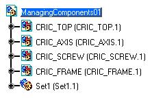
34 Inserting Existing Components Page 34 This task will show you how to import one or more components into an existing assembly. Open the ManagingComponents02.CATProduct document. 1. In the Specification Tree, select ManagingComponents02 and click the Insert Existing Component icon. The Insert an Existing Component dialog box is displayed. 2. Select CRIC_TOP.CATPart from the C:\Program Files\Dassault Systemes\B04doc\online\pstug\samples directory and click Open. The CRIC_TOP (CRIC_TOP.1) is created in the Specification Tree and the Part is displayed in the Geometry area. Depending on the CATIA license you have, you can insert the following components in a CATProduct: CATPart (*.CATPart) CATProduct (*.CATProduct) V4 CATIA Assembly (*.asm) CATAnalysis (*.CATAnalysis) V4 session (*.session) V4 model (*.model) cgr (.cgr) wrl (.wrl) If the Part, Product, model or cgr you insert into an assembly has the same Part Number as the one contained in the assembly, the Part Number conflict dialog box appears. Part Number conflicts when inserting a model 1. Open PartNumberConflict1.CATProduct.

35 Page Insert CARBODY.model into PartNumberConflict.CATProduct. The following dialog box is displayed:
36 Page 36 There is a Part Number conflict because the new component you insert will be in the same document as CARBODY.model (since the component Body1 is not a document). CARBODY.model is directly under PartNumberConflict1.CATProduct. This Part number conflicts panel provides information about: the Part number generating the conflict: CARBODY the path of the document generating the name conflict: C:\TEMP\CARBODY.model the path of the selected source: C:\TEMP\CARBODY.model the Source already existing inside the root product: E:\www\PstEnglish\pstug.doc\src\samples\PartNumberConflict1.CATProduct You have three solutions: Rename... : click the Rename button and the following dialog box is displayed. You can enter a new Part Number. Click OK.
37 Page 37 Click OK. In the Specification Tree, you can see PLANEBODY.model under PartNumberConflict.CATProduct:
38 Page 38 With this Rename option, you create a new reference of CARBODY.model with another Part Number. Reconnect... : click the Reconnect button to reconnect the two entities of CARBODY.model.
39 Page 39 Both entities (CARBODY.model) are overlapping in the geometry space. As a consequence, there is only one instance of CARBODY.model in the Basic View window.

40 Page 40 Automatic rename... : click the Automatic Rename button to have the Part Number changed into CARBODY.1.model.

41 Page 41 For our second example, close PartNumberConflict1.CATProduct without saving. 1. Reopen it. 2. Insert CARBODY.model into Landing_Gear.CATProduct. There is no Part Number conflict because CARBODY's reference is different from the one of CARBODY in Body1. A new local reference has been created.

42 Page 42 For our third example, close PartNumberConflict1.CATProduct without saving. 1. Reopen it. 2. Insert CARBODY.model into Body1.CATProduct. There is a Part Number conflict because there is the same Part Number within the same document Body1.
43 Page 43 Part Number conflicts when inserting a part 1. Open PartNumberConflict1.CATProduct. 2. Insert Landing_Gear_Piston1.CATPart into PartNumberConflict.CATProduct. The following dialog box is displayed: The conflict is due to the presence of the same Part Number (Piston) in Piston and Landing_Gear_Piston1. You can Rename (or use the Automatic Rename option) the new instance Landing_Gear_Piston1. You have the same conflict if you insert Landing_Gear_Piston1.CATPart into PartNumberConflict1 or in Body1.

44 Product Structure If you want to insert the exact copy of this Part, Version Piston, the 5 Release following 13panel will be displayed: Page 44 You are not allowed to open the same Part in the same document. For more information, another functionality is available in the Assembly workbench: Inserting an Existing Components with Positioning, in the CATIA - Assembly User's Guide.


45 Page 45 Inserting CATPart or CATProduct Documents from a Catalog This task shows you how to copy CATPart or CATProduct documents from a catalog into an existing assembly. Open the ManagingComponents01.CATProduct document. 1. Open a catalog, for example the ALL FASTENERS.catalog that you created in the scenario Creating a Catalog in CATIA Component Catalog Editor User's Guide. Double-click on the main chapter, FASTENERS. The entities contained in the selected chapter then appear in the left-hand part of the catalog navigator as shown. Find the chapter containing the entity you want to copy into the assembly. 2. Double-click on this chapter, SCREWS for example. The following results appear in the right part of the dialog box : The entities contained in the selected chapter appear in the form of a table on the right side of the navigator :

46 Two default icons are used : Page 46 the folder icon identifies a chapter the sheet + arrow icon identifies a family in another catalog. 3. Click the Preview tab to visualize the listed entities : 4. You can open an entity in either the Table or Preview tab by double-clicking it. If you want you can now edit the entity just like any other V5 document. To narrow the selection criteria using the keywords you originally chose see Making a Query in a Catalog in CATIA Component Catalog Editor User's Guide. 5. Click on the entity you wish to copy and either click the Copy icon or select the Edit->Copy command. 6. Select the appropriate target i.e. the main product item or any CATProduct document in the specification tree and retrieve the entity from the clipboard by clicking the Paste icon or selecting the Edit->Paste command.

47 Loading Components Page 47 This task will show you how to load a component into an assembly. Loading a component means putting its geometry in memory. You can only load CATPart and CATProduct documents in an assembly. For a model document, you must use the activate representation functionalities, see Managing Representations. Open the ManagingComponents01.CATProduct document. This task can only be completed successfully if you have just unloaded the components (see "Unloading Components"). Select CRIC_BRANCH_3 (CRIC_BRANCH_3.1) in the specification tree or in the geometry and click the Load Components icon. CRIC_BRANCH_3 (CRIC_BRANCH_3.1) is loaded. The link symbol disappears from the document icon in the specification tree. The geometry of the component is displayed.
48 Unloading Components Page 48 This task will show you how to unload a component from an assembly. Unloading a component means removing its geometry from the system memory. A second section explains you that if you unload a CATPart, then you add an existing component that has the same Part Number as the unloaded component, and finally you reload this component, a Part Number conflict occurs. Unloading Components Managing Part Number conflicts on reload You can only unload CATPart and CATProduct documents in an assembly. For a model document, you must use the deactivate representation functionalities, see Managing Representations. Unloading a CATIA document and reloading the same document after several modifications in the CATProduct may lead to Part Number conflicts. This aspect is explained in the second section of this scenario: Managing Part Number conflicts after a Reload. Unloading Components Open the ManagingComponents01.CATProduct document.

49 Page Select CRIC_BRANCH_3 (CRIC_BRANCH_3.1) in the Specification Tree or in the geometry and click the Unload icon. CRIC_BRANCH_3 (CRIC_BRANCH_3.1) is unloaded. The red symbol is removed from the document icon and a link symbol appears in the bottom left corner on the document icon in the specification tree to indicate an unloaded document. The geometry of the component disappears: 2. If the component to be unloaded has been modified, the Unload document dialog box is displayed with three options: Click Yes if you want to save the document to be unloaded
50 Page 50 Click No if you do not want to save the document to be unloaded. WARNING: if you click No, it is impossible to undo the unload operation, to go back to the previous data and retrieve your modifications. Click Cancel if you want to quit the Unload command. 3. If you want to reload the same CATPart, select CRIC_BRANCH_3 (CRIC_BRANCH_3.1) and click the Load icon. Therefore, CRIC_BRANCH_3 (CRIC_BRANCH_3.1) re-appears in the Geometry space and in the Specification Tree its icon indicating the Unloaded status changes into:. Managing Part Number conflicts on reload Open the ManagingComponents01.CATProduct document. 1. Select CRIC_SCREW.1 (CRIC_SCREW.CATPart) in the Specification Tree or in the geometry and click the Unload icon. CRIC_SCREW.CATPart has disappeared in the Geometry space:

51 Page Insert another CATPart having the same Part Number as the one of CRIC_SCREW.1 (CRIC_SCREW.CATPart), for instance: CRIC_SCREW2.CATPart: And you obtain:

52 Page Select CRIC_SCREW.1 (CRIC_SCREW.CATPart) and click the Load icon. A Part number conflicts panel appears because CRIC_SCREW.CATPart and CRIC_SCREW2.CATPart have the same Part Number CRIC_SCREW:
53 Page 53 The OK button is grayed out because the second instance of CRIC_SCREW has already been inserted in the CATProduct and now you need to rename one of the Parts in order to resolve the conflict. 4. Click the Rename or Automatic rename button. The Part Number window is displayed and you can rename the CATPart. Then click OK: 5. The conflict is resolved because CRIC_SCREW2.CATPart has been renamed. Click OK and the panel will disappear: And you can see that both instances of CRIC_SCREW are visible in the Specification Tree and in the Geometry:
54 Page 54

55 Using the Selective Load Page 55 This task will show you how to load partially some components in an assembly. Launching a Selective Load means loading its geometry into the system memory. The difference with the previous functionality, Loading Components, is that Selective Load is more precise, more selective, and you can choose to load only a CATPart and/or a CATProduct in an assembly. It can be applied only when the option Load referenced documents, in Tools -> Options -> General is deactivated. 1. The option Load referenced documents in Tools -> Options -> General must be deselected. 2. Open the AnalyzingAssembly02.CATProduct document.


56 Page CRIC_FRAME.1, CRIC_SCREW.1, CRIC_TOP.1, Set1 (Set1.1) and Subset1.CATProduct are unloaded. A link symbol appears in the bottom left corner on the document icon in the specification tree to indicate an unloaded document or a zebra symbol appears on the CATPart icons meaning that the document's reference cannot be found. The geometry of the component disappears. When the option Load referenced documents is not checked, the geometry is not visible: To compare, if this option were ticked, you would see all the geometry:

57 Page Then, select the element(s) you want to download. To visualize CRIC_FRAME.1 for instance, select this CATPart and click the Selective Load icon. The product Load Management dialog box appears:


58 Page 58 In this dialog box, click the Selective Load symbol and the name of the selected component appears in the left part of the box, with the message "CRIC_FRAME.1 will be loaded." Click on OK. As a consequence, the CRIC_FRAME.1 is loaded : its CATPart symbol geometry appears: comes back in the specification tree and its 3. You can do the same with Set.1[Subset1.CATProduct]. In this example, you can see that this Selective Load functionality can only be applied to one level, there is no incident on the element's children. CRIC_BRANCH_1, CRIC_BRANCH_3.1 and CRIC_JOIN_1 are unloaded :

59 Page 59 As opposed to Selective Load, the Product Initialization option allows you to download CATIA components individually. In order to have CRIC_BRANCH_1, CRIC_BRANCH_3 and/or CRIC_JOIN downloaded, it is necessary to proceed with Selective Load. By the same way the user can put the component in the SHOW / NO SHOW mode by clicking on the icons for SHOW and for NO SHOW.
60 Specifying the Depth Level when opening Product Structure Page 60 Today several options drive the behavior of CATIA V5 in terms of loading and presentation. A command (Product Load Management / Selective Loading) allows to manage progressive load of a Product. This task shows you how to expand 1, 2, all levels in that command. First of all, you need to use the following settings configuration: The option Load referenced documents in Tools -> Options -> General must be deselected. For more information, please refer to Customizing General Settings. 1. Open AnalyzingAssembly02.CATProduct. 2. Download the CATProduct's components by using the Selective Load command. The Product Load Management panel is displayed:
 you want to download. 4.")


61 Page In the Specification Tree, select the component(s) you want to download. 4. Choose a depth level in the list: 1 level, 2 levels or all levels. You can specify the expected open depth using the dedicated combo box. Only 1,2 and All options are accessible. Multiselection capacity is available too. 5. Click the Load icon in the command panel in order to validate the selection. You can see the loading notification in the Delayed actions field:

62 Page Click Ok (or Apply if you want to continue using Selective Load) to load your documents.
63 Setting up the Design Mode Page 63 This task shows you how to set up the Design mode for components in Product Structure context. The Design Mode command changes the.cgr format of the component into the original editable component document. In other words, geometric data is available. This explains why most of the commands are available if Design Mode is activated. You may wish to use the other edition mode referred to as the Visualization Mode. Make sure that the Work with the cache system setting is activated in Tools -> Options -> Infrastructure -> Product Structure -> Cache Management. For more information, see Customizing Cache Setting. Open the ManagingComponents01.CATProduct document.

64 Page Select CRIC_AXIS Then select either: the command Edit -> Representation -> Visualization Mode in the file-menu. or select Representations -> Visualization Mode from the contextual menu or click the icon Design Mode. According to the mode you have chosen, you can see differences in the Specification Tree: Design mode: Visualization mode:
65 Page 65 Moving a CATPart document from Visualization Mode to Design Mode may lead to Part Number conflicts if you had already inserted another element with the same Part Number. For more information, please refer to Setting up the Visualization Mode: Managing Part number conflicts when moving a CATIA document into Design Mode.
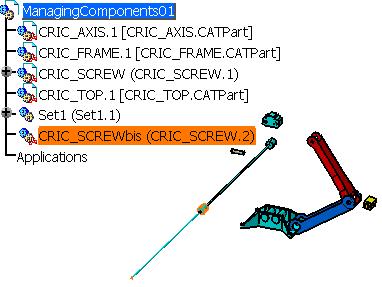
66 Setting up the Visualization Mode Page 66 This task shows you how to set up the Visualization mode for components in Product Structure context and how to manage Part Number conflicts when you shift to the Design Mode: Setting up the Visualization Mode Managing Part Number conflicts when moving a CATIA document into Design Mode The Visualization Mode uses documents in.cgr format. Only the external appearance of the component is visualized. The geometry is not available, which may be useful when you deal with sophisticated assemblies with large amounts of data but only need a few components to work on. You may wish to use the other edition mode referred to as the Design Mode. Setting up the Visualization Mode Make sure that the Work with the cache system setting is activated in Tools -> Options -> Infrastructure -> Product Structure -> Cache Management. For more information, see Customizing Cache Setting. Open the ManagingComponents01.CATProduct document. You can see that the CATProduct is in Visualization Mode because its components are written like this: Instance Name [Document Name]. The geometrical elements of these CATParts cannot be seen in the Specification Tree because their branches are not expandable. 1. Select CRIC_SCREW.1 [CRIC_SCREW.CATPart]. 2. Then select either: the command Edit -> Representation -> Design Mode in the file-menu. or select Representations -> Design Mode from the contextual menu or click the icon Design Mode. CRIC_SCREW.1 [CRIC_SCREW.CATPart] has turned into CRIC_SCREW (CRIC_SCREW.1) and the geometrical elements in CRIC_SCREW.1 can be seen, and therefore selected, in the Specification Tree because its branches are now expandable:

67 Page 67 You can reapply the Visualization mode by selecting the CRIC_AXIS.1 for instance and clicking the Visualization Mode icon. According to the mode you have chosen, you can see differences in the Specification Tree: Design mode: Visualization mode: Managing Part Number conflicts when moving a CATIA document into Design Mode Moving a CATPart document from Visualization Mode to Design Mode may lead to Part Number conflicts if you had already inserted another element with the same Part Number. This task shows you that you can solve this problem by renaming one of the conflicting Parts. Make sure that the Work with the cache system setting is activated in Tools -> Options -> Infrastructure -> Product Structure -> Cache Management. For more information, see Customizing Cache Setting. Open the ManagingComponents01.CATProduct document.

68 Page Select ManagingComponents Click the Insert Existing Component icon. 3. Choose CRIC_SCREW.CATPart: 4. Click Open and you obtain: 5. Select CRIC_SCREW.1 [CRIC_SCREW.CATPart] and click the Design Mode. A Part Number conflict panel is displayed because both entities of CRIC_SCREW have the same Part Number:

69 Page 69 Renaming one of the Part Number is mandatory because the OK button is grayed out in the Part Number conflict panel. 6. Rename CRIC_SCREW.CATPart and click OK: The Part Number is renamed and the conflict is solved: The second Part Number, CRIC_SCREWbis.CATPart, can be inserted in ManagingComponents01.CATProduct:
70 Page 70
71 Deactivating / Activating a Node Page 71 This task shows you how to deactivate / activate a Node in the Product Structure context. Open the CRIC_TERMINAL_NODE01.CATProduct document. 1. Select the Product CRIC_SCREW. 2. Either select the command Edit -> Representation -> Deactivate Node or select the Deactivate icon. This functionality allows you to mask an active representation from a particular node (at the level of CRIC_SCREW) in the specification tree and in the geometry :

72 Page By re-select the same node, CRIC_SCREW, and the command Edit -> Representation -> Activate Node or clicking the Activate icon in the geometry :, the elements re-appear both in the tree and

73 Page 73 By this means, you choose to visualize the geometric representation of CATIA elements, belonging to a CATProduct. With the Deactivate Node functionality, only the selected element is hidden. Whereas with the Deactivate Terminal Node functionality, the last node's elements of the selected node are masked. For more information, see the following chapter Deactivate / Activate Terminal Node. If you close a CATIA document containing deactivated CATParts or CATProducts, when reopening your document the deactivated elements are activated. As opposed to the SHOW / NO SHOW functionality : the entities in the NO SHOW mode remain in this mode when you reopen the document. Both functionalities, Deactivate / Activate Node and SHOW / NO SHOW, are very similar but with the deactivate option you liberate the geometrical space, a deactivated representation is unloaded and it is no longer stored. On the contrary, with the SHOW / NO SHOW mode there is a more important quantity of stored memory. The activate / deactivate functionality allows a more precise selection and de-selection, especially with the Terminal Node deactivation. You can activate or deactivate Shape representation in Tools -> Options -> Infrastructure, select the Product Structure tab and check the box entitled Do not activate default shapes on open. The entity representation disappears, it is a profit for memory space and its icon in the specification tree changes into :. You can work only on the tree. For more information about activate or deactivate Shape representation, see Specification Tree.
74 Deactivating / Activating a Terminal Node Page 74 This task shows you how to deactivate / activate a Terminal Node in the Product Structure context. Open the CRIC_TERMINAL_NODE01.CATProduct document. 1. Select CRIC_SCREW. 2. Select the command Edit -> Representation -> Deactivate Terminal Node. The representation of Terminal Nodes (of CRIC_BRANCH_3 et CRIC_BRANCH_1) disappears from the specification tree and the geometry, and their icon in the specification tree changes into :.


75 Page By re-select the same node, CRIC_SCREW, and the command Edit -> Representation -> Activate Terminal Node, the elements re-appear both in the tree and in the geometry :
76 Page 76 By this means, you can choose to visualize or hide CATIA elements. Under a selected node, the elements of the very last node are masked.

77 Page 77 Activating a Terminal Node with a Progress Bar This task consists in visualizing the activation of shapes (using the Activate Terminal Node Command) with a progress bar that gives the number of activated shapes out of the total deactivated shapes. For more information about the progress bar, please refer to Opening a CATProduct with a Progress Bar. Open the AnalyzingAssembly01.CATProduct document. Select the root product AnalyzingAssembly01 and the command Edit -> Representation -> Deactivate Terminal Node. All the shapes are deactivated. Or you can deactivate shape representation in Tools -> Options -> Infrastructure, by selecting the Product Structure tab and checking the box entitled Do not activate default shapes on open. Then, open the AnalyzingAssembly01.CATProduct. All the shapes are deactivated: For more information about this functionality, please refer to Deactivate Terminal Node. Select the root product AnalyzingAssembly01 and the command Edit -> Representation -> Activate Terminal Node. The shapes are progressively downloaded.

 and")
78 Page 78 And you can see the progression of the downloading of the shapes associated to a terminal node: This operation is activated by default (there is no setting). When this dialog box disappears, the whole geometry (assembly) and the Specification Tree are displayed.
79 Managing Representations Page 79 This task describes the notions and operating modes you will need to use a context-specific representation in your assembly structure. A context-specific representation is a hierarchical design of an assembly in a specific context. For this version you can only use a geometrical representation from a Version 4 model document. Once you have created a new component or inserted a Version 4 model as an existing component in an assembly, you can associate, remove, replace, rename, activate or deactivate a context-specific representation to this product. You must work with the Cache system to be able to manage representations. For more information about the Cache system, please refer to Customizing Cache Settings. Open the ManagingComponents05.CATProduct document. 1. Select a product in the specification tree. For instance, select CRIC_FRAME.1.
80 Page Click the Manage Representations icon or right-click on the.model and select the Representations -> Manage Representations... contextual command. The Manage Representations dialog box appears.

81 Page 81 It displays: the Name of the representation the Source file of the representation the Type of representation whether the representation is the Default representation of the product whether the representation is Activated or not. 3. Select CRIC_FRAME if not already done and click the Associate... button. The Associate Representation dialog box is displayed. 4. Select the.model document of your choice from the C:\Program Files\Dassault Systemes\B04doc\online\pstug\samples directory and click Open. When you select the.model document, CRIC_JOIN.model, in the Manage Representations box, you can then activate or deactivate its representation in the specification tree. The first representation CRIC_FRAME.model is activated and set as the default representation.

82 Page 82 The representation is associated with the Product and displayed in the specification tree and in the geometry area.
83 Page 83 The representation is activated and set as the default representation. You can associate as many representations as you need, but only one must be set as default. In this case other representations are not displayed in the specification tree and in the geometry area. To change the default representation of a product, select one of its representations and click the Set As Default button. To deactivate a representation of a product, select a representation in the Manage Representations dialog box and click the Deactivate button. The representation is deactivated from Product in the specification tree and in the geometry area and No is displayed in the Activated column of the Manage Representations dialog box. To activate a representation of a product, select a representation in the Manage Representations dialog box and click the Activate button. The representation is activated in the specification tree and in the geometry area and Yes is displayed in the Activated column of the Manage Representations dialog box. To replace a representation, select a representation in the Manage Representations dialog box and click the Replace... button. The Replace Representation dialog box is displayed. Select the model document from the chosen directory and click Open. The representation is replaced in Product in the Specification Tree, in the geometry area and in the Manage Representations dialog box. When you replace a constrained representation, even if its constraints have been deleted, you are in the reconnect representation context. See Reconnecting a Replaced Representation in CATIA - Assembly User's Guide. When you replace a deactivated representation, the replacing representation is automatically activated. If you possess a Digital Mock-Up (DMU) Navigator license, the model is read as.cgr format, you may convert it in.model format with the Design Mode command. See Edition Mode. To rename a representation, select a representation in the Manage Representations dialog box and click the Rename... button. The Rename Representation dialog box is displayed. Define a new name or select an existing name in the combo box.the representation is renamed in the Manage Representations dialog box. However, this has no effect on the feature names in the specification tree as there is no relation between representation names and feature names. Renaming the instance name of the Part with this character "!" breaks the Publication Links, a warning message appears and you cannot rename it. To remove a representation, select a representation in the Manage Representations dialog box and click the Remove button. The representation is removed from the Product in the specification tree, in the geometry area and in the Manage Representations dialog box

84 Page As it was mentioned above, you can only use a geometrical representation from a.model document. In Product Structure and DMU, you cannot associate a representation to a.catpart document. If you select a.catpart document (CRIC_AXIS) in the specification tree and click the Manage Representation icon, note that you are not allowed to click on the Associate button.

85 Page 85 To sum up, you can associate any kind of document (.model,.catpart,.cgr) to a CATProduct but not to a CATPart. This security prevents you from modifying the content of the CATPart. If you want to know how to manage representations as alternate shapes automatically, in DMU Optimizer, see Customizing DMU Optimizer Settings in CATIA - Infrastructure User's Guide. From CATIA Version 5, new alternate shapes can be saved in VPM, directly in the database : when the dialog box entitled Synchronization is displayed, you can click on OK. For more information about alternate shapes in VPM, refer to Managing Alternate Shapes - Saving and Deleting Alternate Shapes in VPM User's Guide.


86 Reordering the Tree Page 86 This task shows you how to reorder components within the specification tree. Open the ManagingComponents01.CATProduct document. 1. Select ManagingComponents Click the Reorder Tree icon. A dialog box appears, listing the components constituting ManagingComponents01 and providing three buttons for reordering these components.
87 Page 87 The first arrow moves the selected component to the top of the list. The second arrow moves the selected component to the bottom of the list. The third button moves the selected component to the place of another component you need to select. 3. Select CRIC_FRAME and click the second arrow twice. CRIC_FRAME then appears after CRIC_TOP on the list. 4. Click Apply to preview the result: 5. Select CRIC_TOP and click the third button. 6. Select CRIC_AXIS to determine the location of CRIC_TOP. CRIC_TOP is now on top of the list. 7. Click OK to confirm the operation. The application closes the dialog box and updates the specification tree. The tree is reordered as follows:
88 Page 88

89 Isolating a Part Page 89 This task will show you how to isolate a part in an existing assembly in order to move it independently from the other contextual parts. Open the IsolateFunction.CATProduct document. The option "Keep link with selected object" must be selected in Tools -> Options -> Infrastructure -> Part Infrastructure. 1. Double-click on Sketch1 in Skeleton.CATPart in order to edit it. For instance, move the left side of Ctx1.CATPart. And go back into Product Structure workbench. Before the manipulation of Ctx1.CATPart: After: 2. Click the Update icon (in Assembly Design Workbench, also available via Edit->Update and the Update contextual command). As a consequence, Part3 (Part3.1) moves in order to follow the movement of Ctx1 (Part2.1) and the hole coincides between the two parts. If you modify one Part, the other one adapts itself to this change. This is due to the fact that both CATParts depend on the same document, Skeleton (Part1.1), and the option Keep link with selected object is activated.
90 Page 90 Ctx1 (Part2.1) and Part3 (Part3.1) are a contextual parts, they depend on the Sketch1 in Skeleton (Part1.1) in which they were created. 3. If you want to make modifications impacting only on Ctx1 (Part2.1), select in the contextual menu of Ctx1 (Part2.1) Component -> Isolate Part. When Ctx1 (Part2.1) is isolated, its symbol in the Specification Tree changes from to meaning that it is no longer a contextual part:

91 Page Modify again the CATPart within the Sketcher and return in the Assembly Workbench. Only Part3 (Part3.1) has turned red in the Geometry space.

92 Page Update the document. As a result, Part3 (Part3.1) has not moved to adjust to Ctx1 (Part2.1).
93 Page 93 You can move independently Ctx1.CATPart from Part3.CATPart. As a consequence, when CTX1 is displaced, Part3 does not move and the hole does not coincide between the two CATParts.

. 2.")
94 Deactivating / Activating a Component Page 94 This task will show you how to deactivate a component from an assembly. Deactivating a component means removing its geometry. In the same CATIA session, open the following documents: AnalyzingAssembly02.CATProduct Subset1.CATProduct Product4 that you have created by selecting File -> New... Product and by inserting the existing component, Subset1.CATProduct. In the menu bar, select Window -> Tile Vertically in order to be able to visualize the three documents in the same CATIA window. Subset1.CATProduct exists in AnalyzingAssembly02.CATProduct, Subset1.CATProduct and Product4. 1. In AnalyzingAssembly02.CATProduct, select CRIC_BRANCH_1.CATProduct (in Subset1.CATProduct). 2. Right click it and select the CRIC_BRANCH_1.1 object-> Activate/Deactivate Component contextual command. Note that all the instances of CRIC_BRANCH_1.CATProduct disappear in the geometry space and their symbol is transformed into:.

95 Page 95 CRIC_BRANCH_1.CATProduct has been deleted in AnalyzingAssembly02.CATProduct, Subset1.CATProduct and Product4. Its symbol has changed in the Specification Tree:. Its shape is deactivated and there are no traces of its specifications in the Bill Of Material (Analyze -> Bill Of Material).


96 Page 96 Deactivating a Component means deleting its representation and instance. The operation is simultaneous in all the CATIA documents containing this element, CRIC_BRANCH_1.CATProduct, because it is the reference document. This operation is shared by all the instances of this part. You can apply this functionality on CATProducts, CATParts and models. This command does not free the memory and the symbol in the specification tree shows you that it is still possible for you to reactivate it by the reverse operation: Right click it and select the CRIC_BRANCH_1.1 object-> Activate/Deactivate Component contextual command. 3. In AnalyzingAssembly02.CATProduct, select Subset1.CATProduct, right click it and select the Set.1 object-> Activate/Deactivate Component contextual command. Only one component is deactivated in AnalyzingAssembly02.CATProduct because it is not a reference instance. Subset1.CATProduct is no longer referenced in the BOM:
: Hiding objects (No Show): does not free the memory; The object is no longer displayed: it has been transferred into")
97 Page 97 Note that this operation cannot be applied on a root product. Comparison with closely related functionalities (illustrated by the table below): Hiding objects (No Show): does not free the memory; The object is no longer displayed: it has been transferred into the No Show space. But it is still visible in the BOM. Unloading a component: geometry disappears, only the instance is left and the reference no longer exists, but you have access to its information in the BOM. It frees the memory. Deactivating a Node: the representation is masked in the geometry and the specification tree, but you can find its data in the BOM. Deactivating a Terminal Node: the representation of Terminal Nodes disappears from the specification tree and the geometry. Under a selected node, the elements of the very last node are masked. NO SHOW Hiding Components UNLOAD Unloading a Component Visualization (Shape Representation) NO BOM (Bill of Material) YES Deactivating a Node NO YES Deactivating a Terminal Node Deactivating a Component Accessibility (possibility of applying constraints) YES, you can apply constraints between the hidden object and the other components in the Show space. NO YES NO YES, you can apply a constraint even if the shape is deactivated. Effects on aggregated objects YES, the No Show icon is propagated on the aggregated objects. The aggregated objects are no longer visible but they are not unloaded. NO YES YES N/A NO NO NO N/A The children are not visible in the Specification tree and in the Geometry.
98 Page 98
99 Defining Contextual Links Page 99 This task will show you how to change the context of a part in an existing assembly, how to make it contextual or not (and make it depend or not on another document). Open the ChangeCtx.CATProduct document. 1. Copy Pic1.CATPart and paste it in Poteaux.CATProduct. Drag and drop the compass on Pic1 (Pic1.2) and move it. As Pic1 (Pic1.2) is a copy of Pic1 (1.1), it is hidden behind Pic1 (1.1) in the Geometry space. To see the second cylinder you need to drag and drop the compass on Pic1 (Pic1.1) and move it and you will be able to visualize both cylinders. If you want to be more familiar with the compass manipulation, you can read Manipulating Objects Using the Mouse and the Compass in CATIA - Infrastructure User's Guide. This tutorial will show you how to move and rotate viewpoints and non-constrained objects. The initial document: After the Copy / Paste operation:
100 Page 100 Pic1 (Pic1.1) is a contextual part and Pic1 (Pic1.2) is in blue. and Pic1 (Pic1.2) is the second or subsequent instance of this contextual part. In the geometry space, Pic1 (Pic1.1) is in pink 2. In the contextual menu of Pic1 (Pic1.2), select Components -> Change Context. Pic1 (Pic1.1) is no longer a contextual part. The following dialog box is displayed: Click OK. For more information about this panel, please refer to the Change Context panel described below. As a consequence, Pic1 (Pic1.2) gets red because it has no link any more with the contextual part and therefore with the Upper and Lower Surfaces in Masters.CATProduct.
101 Page Click the Update icon (in Assembly Design Workbench, also available via Edit->Update and the Update contextual command).
102 Page 102 Only Pic1 (Pic1.2) is set between the Upper and Lower surfaces, its keeps link with the Surfaces whereas Pic1 (Pic1.1) has lost its links with the Surfaces' geometry (no connection) because it is no longer a contextual part. The Change Context functionality allows you to create a local copy of Pic1 (Pic1.1). Pic1.2 becomes a definition instance. 4. This first demonstration is finished, delete Pic1 (Pic1.2). 5. For the next demonstration, Copy Pic1 (Pic1.1), select Poteaux.CATProduct and the command Edit -> Paste Special. The Paste Special dialog box is displayed : select Break link and click on OK. Drag and drop the compass on Copy of Pic1 (Copy of Pic1.1) and move it.
 remains a contextual part and the Copy of Pic1 becomes a contextual part (green gear in its icon) as")
103 Page Click in the contextual menu of Copy of Pic 1, select Component -> Change Context. Pic1 (Pic1.1) remains a contextual part and the Copy of Pic1 becomes a contextual part (green gear in its icon) as well.

104 Page Update the document and the green gear of the Copy of Pic 1 is still green. Its geometry adapts itself to the Surfaces.
105 Page 105 With the Change Context functionality, both Pic1 and Copy of Pic1 are contextual: they keep a link with ChangeCtx.CATProduct. Change Context panel: 1. Open ChangeCtx.CATProduct. 2. Insert a new product and call it Pics (Pics1). 3. Copy the contextual Part, Pic1 (Pic1.1), and paste it into Pics. This copy of Pic1 is the second or subsequent instance of this contextual part.
 gets red because it has no link any more with the contextual part and therefore with the Upper and Lower Surfaces in Masters.")
106 Page In the contextual menu of Pic1 (under Pics), select Components -> Change Context. Pic1 becomes a contextual part. As a consequence, Pic1 (in Poteaux) gets red because it has no link any more with the contextual part and therefore with the Upper and Lower Surfaces in Masters.CATProduct. The change Context dialog box appears:
107 Page 107 This panel provides information about the context you want to change and the external references of the instance Pic1 (in Pics): Expected status: To solve, meaning that links have to be restored between Pic1 and Surface.2 (belonging to the Previous pointed element Face and to the Previous pointed instance Upper.1) and between Pic1 and Surface.3 (belonging to the Previous pointed element Face and to the Previous pointed instance Lower.1) in External References.

108 Product Structure the Publication path with Surface.2 should be Version..!..!Masters.1UpperSurface 5 Release 13 and the publication path with Surface.3 Page should 108be..!..!Masters.1LowerSurface. the New pointed elements and instances have not been selected yet. 5. To select the New pointed elements and instances, press the button twice, corresponding to the number of the previous levels:..!..!masters.1uppersurface. Click OK. The links are converted into..!..!..!masters.1uppersurface and..!..!..!masters.1lowersurface.
109 Page To make Pic1 (in Poteaux) a contextual part, select the Components -> Change Context contextual command. The change context dialog box is displayed: 7. To select the New pointed elements and instances, press the button three times, corresponding to the number of the previous levels:..!..!..!masters.1uppersurface. Click OK.
110 Pic1 (in Poteaux) becomes a contextual part and you can update your document. Page 110
111 Defining Contextual Links: Editing and Replacing Page 111 Commands Product Structure Version 5 Release 13 This command called "Define Contextual Links" uses the existing panel of the "Change Context" command. Therefore, the command can be used in the Change Context command. New buttons have been created in the Change Context panel: Edit and Replace. The Define Contextual Link command enables to define (change) all the contextual links before and during the Change Context command. You can also make the operation on contextual parts, to modify unsolved links. You have the possibility to: re-root each link, using the Edit button, pointing in 3D space or in graph re-root links, using the Replace button, changing one or many instance names change the numbers of each link, using Replace Open the DefineCtxLinks.CATProduct document.
, select Components ->Define Contextual Links. The following dialog box is displayed: 2.")

112 Page 112 How to Replace a Part or a Publication 1. In the contextual menu of CtxPart (CtxPart.2), select Components ->Define Contextual Links. The following dialog box is displayed: 2. In the Change Context dialog box, select the Publication path of Solid.1 and click the Replace button. 3. Select another component in the Specification Tree, for instance the Publication: PartBody, which will be the new pointed element. And you can immediately visualize the expected status: Connected.
113 Page Before going to the next task, please close DefineCtxLinks.CATProduct without saving it. How to Edit a Part or a Publication First example: Open the DefineCtxLinks.CATProduct document. 1. In the contextual menu of CtxPart (CtxPart.2), select Components->Define Contextual Links. 2. In the Change Context dialog box, select the Publication path of Solid.1 and click the Edit button, the following panel appears displaying the graphical view of the external references which you can compare with the product structure graph. The Edit button allows to re-root the external links of a contextual part with other elements.

114 Page 114 The part Support2.1 and the publication PartBody are highlighted in red because Support2.1 should be under Compo2.CATProduct. 3. In the contextual menu of Support2.1, select the Insert Node before command to add a node, SubCompo2.CATProduct between Compo2.1 and Support2.1. You can directly select SubCompo2.CATProduct in the Specification Tree. And you obtain: Both the Part and the Publication are no longer highlighted; their links are restored thanks to the creation of the new node SubCompo Click OK. The Solid.1 is reconnected and it acquires a new pointed element, PartBody, and a new pointed instance, Support2.1:
, select Components->Define Contextual Links. 2. In the Change Context dialog box, select both Datum.1 and Curve.2 and click the Edit button:")
115 Page Click OK. 6. Before going to the next example, please close DefineCtxLinks.CATProduct without saving it. Second example: Open the DefineCtxLinks.CATProduct document. 1. In the contextual menu of CtxPart (CtxPart.2), select Components->Define Contextual Links. 2. In the Change Context dialog box, select both Datum.1 and Curve.2 and click the Edit button:

116 Page 116 The following panel appears: The reference of Support4.1 cannot be found under Compo1.1 because it has been renamed: Support Select Support4.1 and the contextual command Replace Node:

117 Page Select another component in the Specification Tree: Support1.1, which will be the new pointed element. And the link is restored. 5. Click OK. 6. The other solution is to Edit the node of Support4.1: 7. And you can enter a new name, for instance: Support.1. Click OK. And you obtain:
118 Page Click OK. The new pointed instance is Support.1 and the new pointed elements are Sketch.1 and VDirection. 9. Before going to the next example, please close DefineCtxLinks.CATProduct without saving it. Third example: Open the DefineCtxLinks.CATProduct document. 1. In the contextual menu of CtxPart (CtxPart.2), select Components->Define Contextual Links. 2. In the Change Context dialog box, select Surface.2 and click the Edit button:

119 Page 119 The following panel appears: The reference of Support1.1 cannot be found under SubCompo2 because its position has changed: it is under Compo2.1 and not under SubCompo Select Support1.1 and the contextual command Replace Node: select Support1.1 in the Specification Tree or select another Publication under Support1.1: Extrude2. And you obtain: The other solution is to delete Subcompo2:


120 Page 120 As a consequence, Support1.1 is directly under Compo2.1: 4. Click OK and the links are reconnected between Support1.1 and Compo2.1. The Edit functionality is the same with Publications. 5. Finally, you can update your document.
121 Using Flexible Sub-Products Page 121 In the product structure from earlier versions, you could only move rigid components in the parent product. Now, in addition to this behavior, you can dissociate the mechanical structure of a product from the product structure, and this within the same CATProduct document. As a consequence, you can move the components of a sub-product in the parent product. In a first place, this task recalls the behavior of rigid products, then it illustrates how to make sub-products flexible and eventually shows you how to analyze the mechanical definition of a product whenever this product includes flexible sub-products (and components attached together). For more information about components attached together, see Fixing components together in CATIA Assembly User's Guide). Open the Articulation.CATProduct document. 1. The product "Articulation" includes one CATProduct and two CATPart documents as follows: 2. Drag and drop the compass onto link (link.1), then select link (link.1) and drag it. The whole chain -and not link.1 only- is moved.
 flexible, right-click it and select the Chain.1 object -> Flexible/Rigid contextual command.")
 independently from link (link.2).")
122 Page Undo this action to return to the initial state. 4. To make chain (chain.1) flexible, right-click it and select the Chain.1 object -> Flexible/Rigid contextual command. You can notice that the little wheel to the left corner of the chain icon has turned pink is a light blue stroke to identify the flexible sub-product. and there 5. You can now move link (link.1) independently from link (link.2). For example drag and drop the compass onto link (link.1) and move it in the direction of your choice.
 within Articulation.CATProduct.")
 rigid, right-click it and select the Components -> Flexible/Rigid contextual command. A message window appears. 8.")
123 Page 123 When a sub-product is flexible, you can apply updates to it, move it when constrained and set constraints to it. 6. Copy and paste chain (chain.1) within Articulation.CATProduct. You can notice that the property "flexible" is copied too. 7. To make chain (chain.2) rigid, right-click it and select the Components -> Flexible/Rigid contextual command. A message window appears. 8. Drag and drop chain (chain.2) to clearly see both instances of chain.catproduct.
 using the compass.")

 is rigid, it inherits the new position of the original")
124 Page Open chain.catproduct and move link (link.1) using the compass. The role of the compass is to : look for the flexible product move the highest product that is rigid or the first flexible component. You can notice that because chain (chain.2) is rigid, it inherits the new position of the original chain.catproduct. Conversely, chain (chain.1) remains unchanged.
. Flexible sub-products can be moved individually, without considering the position of the original product.")
 operates downwards. A component's position is borne by its reference.")
125 Page 125 What you need to keep in mind is that rigid sub-products are always synchronous with the original product, whatever mechanical modification you perform (new dimensions or new positions for the original product). Flexible sub-products can be moved individually, without considering the position of the original product. However, flexible sub-assemblies inherit mechanical modifications to the original product. This command works upwards in the Specification Tree whereas the "stiffening" command (rigid mode) operates downwards. A component's position is borne by its reference. In a rigid mode, the position is carried by the first instance, the father of which is a reference (or a root product). In a flexible mode, the position is carried by the instance. Making a component flexible means that you are overloading its children's position. 10. Select the Analyze -> Mechanical Structure... command to display the mechanical structure of Articulation.CATProduct. This mechanical structure looks different from the product structure.
126 Page 126 This display is merely informative. Note that you can use the Reframe graph contextual command and the zoom capability to improve the visualization, but also the Print whole contextual command to obtain a paper document. For information on printing, please refer to Printing Documents in CATIA Infrastructure User's Guide. You can save the CATProduct with its flexible sub-products and when you re-open the CATProduct, the modifications are visible, these flexible components are kept in memory.

127 Page 127 Moving the Components of a Sub-Product in the Parent Product This task illustrates how to move a component belonging to a rigid structure (the Parent Product is rigid). It implies that the instance of its parent product's reference is moved. Open the Articulation.CATProduct document. The product "Articulation" includes one CATProduct and two CATPart documents (in rigid mode) as follows: 1. Edit or double-click Articulation to make it UI Active (User Interface Active, in blue color). 2. Select link.1 and and move it with the compass:


128 The compass is not positioned on link.1 because the component is rigid and this is its instance within the product, Chain.1, which is taken into account. Page As a result, you cannot move link.1 independently from link.2; the whole assembly (Chain.1) moves because its sub-components (link.1 and link.2) are rigid: 4. Undo this action to return to the initial state. 5. Edit or double-click Chain.1 to make it UI Active (in blue color) in order to be able to move the instance of the link.1 reference.
 independently from link (link.2).")
129 Page Select link.1 and and move it with the compass: Note that in this case, the compass is positioned on link You can now move link (link.1) independently from link (link.2). Therefore, to move a sub-product in a rigid structure, you need to edit its parent product.


130 Replacing a Component Page 130 The first task consists in replacing a component and showing the impacts of this action. Using the Replacement Component command means replacing one component with another. The second task explains what can be the impacts of replacing a component whose Part Number is same as the replaced element, and what can be done to solve the conflict. The third task shows you that you can replace several instances. The process is the same but when a component dialog box is displayed, you select the component of your choice and tick the MultiInstances box in order to replace all instances. Replacing a Component by another one in Session The Impacts of the Replace Command Replacing a Specific Instance or All Instances of a Reference The Instance name is always kept so that links (external references) are not broken. Replacing a Component by another one in Session If you want to replace your CATIA documents by downloaded ones, you need to activate the following option, in Tools -> Options -> General -> Document -> Document Environments - Loaded document: Allowed. Open the AnalyzingAssembly02.CATProduct.
 and the Replace Component contextual command.")

131 Page Right-click CRIC_SCREW (CRIC_SCREW.1) and the Replace Component contextual command. The following panels are displayed: 2. Click Cancel in the file Selection window. The Browse panel is still available. 3. Click the Loaded document icon. A Session document window appears:

132 Page Select one of the downloaded documents, for instance: Subset.CATProduct. An Impacts on Replace window is displayed, showing you what can interfere with the other downloaded documents. For more information about the impacts on replace, please refer to the following section. 5. In the Impacts on Replace, click OK if all the replacing impacts have resolved and you obtain: The Impacts of the Replace Command Open the ReplaceImpacts.CATProduct document.
 and click the Replace Component icon.")
133 Page 133 Note: depending on the document environments you have allowed in the Document settings, an additional panel may appear simultaneously to let you access your documents using an alternate method. For detailed information, refer to Opening Existing Documents Using the Browse Panel. 1. Select PartWithImpacts (PartWithImpacts.1) and click the Replace Component icon. The File Selection and Browse panels are displayed:

 Name of the impacted objects (which is connected to PartWithImpacts.")
134 Page Click Cancel in the File Selection panel; the Browse panel becomes activated. Or if you select Support1.CATPart for instance, in the File Selection panel, the Browse panel disappears and, you do not need to follow the steps 3 and Click the File icon and another File Selection window appears. 3. Select Support1.CATPart for instance. An Impacts on Replace panel appears: This panel shows you the impacts of the Replace command on PartWithImpacts.CATPart. You can see the impacted objects (2 Publications, 1 External Reference and 1 Constraint) that can be re-connected or not. You have access to the following information: Type of the impacted objects (Publication, Contextual Design Connection) Name of the impacted objects (which is connected to PartWithImpacts.CATPart) Source or path of the impacted objects You can interrupt the Replace operation by clicking the Cancel button.
135 Page There is a question in the panel: By default, the YES option is checked. It means that all the instances will be replaced (and the Part number conflict panel does not appear because it is no longer needed). If you click NO, only the selected instance will be replaced but, in the case of a Part Number conflict, the Part Number Conflict dialog box appears. For more information about Part Number Conflict, please refer to the following scenario. 5. Click OK and the Impacts on Replace dialog box disappears. You can visualize the impacts in the Geometry and in the Specification Tree.
136 Page Update your document and the following warning points out the impacted objects: Surface.1 no longer has its External Reference. You can however use the replace command on the objects that may be impacted. The links can be modified but not necessarily broken. 7. Click Close. The symbol next to the External Reference means that the part is not connected with the correct External Reference. The other Publications with a broken link are represented with this yellow exclamation mark with the root document has been lost. meaning that the link

137 Page 137 Replacing a Specific Instance or All Instances of a Reference This task consists in replacing first, a Specific Instance, and finally All Instances of a reference. As it was described in the previous section the user activates the Replacement Component icon to replace one component with another. This command automatically chooses the first instance of the object that is going to be replaced. Open the 16cubes.CATProduct document:
138 Page 138 This document contains two identical CATProducts : 8 cubes (8 cubes.1) and 8 cubes (8 cubes.2). Both CATProducts have the same CATParts : Cube (Cube.1) and Cube (Cube.2). 1. First of all, select Cube (Cube.1) and click the Replace Component icon. The Replace Component dialog box is displayed, select Cube2.CATPart and click Open:
139 Page Click Open and the Impacts on Replace dialog box appears, with the following message: If you choose to replace Cube(Cube1.1) with Cube2(Cube1.1), there is a Part Number conflict because both entities have the same Part Number (Cube). Therefore, if you click: YES, all the instances will be replaced (and the Part Number conflict panel does not appear because there is no longer any conflict). NO, only the selected instance will be replaced but, in the case of a Part Number conflict, the following dialog box appears: 3. Select Yes and click OK and another panel appears, displaying the Incident Report: it is a warning telling you that the component you are inserting is read-only. 4. Click Close.

 and click the Replace Component icon. 7.")
140 Page 140 There is no Part Number conflicts panel (no impact on Cube (Cube.1)) because the replacing component, Cube2.CATPart, does not create any conflict since all the "cube" Part Numbers have been replaced: Wherever the element's instance is in the product, it is replaced by the new component. In our example, the Multi-Instances functionality looks for all the instances of the reference Cube (Cube.1) in the product and replaces them in the whole document. 5. Close 16cubes.CATProduct without saving it. Re-open it. 6. Repeat the same operation: select Cube (Cube.1) and click the Replace Component icon. 7. In the File Selection window, click Open and the Impacts on Replace dialog box appears. 8. Click No to replace only one instance:
141 Page 141 And two panels appear: the Incident Report: it is a warning telling you that the component you are inserting is read-only. Click Close. the Part number conflict panel; you can Rename (or use the Automatic rename option) the new instance Cube2.CATPart so that there is no longer conflict with the other Part Numbers (you do not replace): 9. The (New) Part Number panel appears. Select this line (Cube) and click the Rename button. 10. Click OK. In the Part number conflicts, you can see that the name of the Part Number (of Cube2.CATPart) has changed into CubeBis.

 has not been replaced by Cylinder01.")
142 Page Click OK and you obtain: As a consequence, only a Specific Instance, Cube (Cube.1), is replaced by Cube2.CATPart (whose Part Number is different from the one of Cube (Cube.1)) in the Specification Tree and in the Geometry area. Note that the last entity of Cube (Cube.1) has not been replaced by Cylinder01.CATPart because the entity's instance is not at the same level: For more information about Part Number conflict, please refer to Insert Existing Component.
143 Page 143 Replacing a Specific Instance or All Instances of a Reference This task consists in replacing first, a Specific Instance, and finally All Instances of a reference. As it was described in the previous section, Replacing a Component, the user activates the Replacement Component icon to replace one component with another. This command automatically chooses the first instance of the object that is going to be replaced. Open the 16cubes.CATProduct document : This document contains two identical CATProducts : 8 cubes (8 cubes.1) and 8 cubes (8 cubes.2). Both CATProducts have the same CATParts : Cube (Cube.1) and Cube (Cube.2).
144 Page First of all, select Cube (Cube.1) and click on the Replace Component icon. The Replace Component dialog box is displayed, select Cylinder01.CATPart and click Open: 2. Click Open and the Impacts on Replace dialog box appears, with the following message:
145 If you choose to replace Cube(Cube1.1) with Cube2(Cube1.1), there is a Part Number conflict because both entities have the same Part Number (Cube). Page 145 Therefore, if you click YES, all the instances will be replaced (and the Part number conflict panel does not appears because it is no longer needed). If you click NO, only the selected instance will be replaced but, in the case of a Part Number conflict, the following dialog box appears: Then click OK and another panel appears, displaying the Part Number conflicts: You can Rename (or use the Automatic Rename option) the new instance Cube2.CATPart. For more information about Part Number conflict, please refer to Insert Existing Component. 3. If you click No, you replace only one instance. As a consequence, a Specific Instance, Cube (Cube.1), is replaced by Cylinder01.CATPart in the specification tree and in the geometry area:
 and click the Replace Component icon. The Replace Component dialog box is displayed, select Cylinder01.")
146 Page 146 Note that the last entity of Cube (Cube.1) has not been replaced by Cylinder01.CATPart because the entity's instance is not at the same level. 4. Close without saving and re-open the 16cubes.CATProduct document. 5. Repeat the same operation : Select Cube (Cube.1) and click the Replace Component icon. The Replace Component dialog box is displayed, select Cylinder01.CATPart and click Open: The Impacts on Replace dialog box appears with the following message:
147 Page 147 If you click Yes, all the instances of Cube (Cube.1) are replaced by Cylinder01.CATPart: the last entity of Cube (Cube.1) in the Specification Tree is also replaced by Cylinder01.CATPart.
148 Page 148 Wherever the element's instance is in the product, it is replaced by the new component. In our example, the Multi- Instances functionality looks for all the instances of the reference Cube (Cube.1) in the product and replaces them in the whole document.

149 Editing Components Page 149 This task lists the ways of editing components in an existing assembly. The Cut command removes the selected component instance and puts it in the clipboard. The Copy command puts a copy of the selected component instance into the clipboard. The Paste command creates a new component instance from the clipboard. The Delete command removes the selected component instance. For more information about the deletion of the instance of a contextual CATPart, please see below. The drag and drop capability allows you to copy or move one component to another. For each edition operation you must select the components in the specification tree. Remember that the components you wish to move or paste may have one or more constraints. Once the component is moved or pasted, the constraints may be broken. See also Copying and Pasting Objects CATIA - Infrastructure User's Guide. What happens when you delete the instance of a contextual part This task shows you how a contextual part can be modified by a Delete operation and it can be saved in the Save Management panel. Open the document: ChangeCtx.CATPart. You can display document links by selecting the Edit->Links... command. Click the Pointed documents tab to display only the documents pointed to by the current object. Select Poteaux.CATProduct and click Open. And you can visualize both ChangeCtx.CATProduct and Poteaux.CATProduct:
 in the Specification Tree represents a part and the green gear signifies the \"original\" instance of a part that is contextual (driven by another part, built with another part's data) in a")
 depends on them, which explains why the External References file appears under Pic1 (Pic1.1) in the Specification Tree. If you modify Upper (Upper.1) and/or Lower (Lower.")
150 Page 150 This symbol next to Pic1 (Pic1.1) in the Specification Tree represents a part and the green gear signifies the "original" instance of a part that is contextual (driven by another part, built with another part's data) in a CATProduct. Pic1 (Pic1.1) is a contextual part and it has been built with Upper (Upper.1) and Lower (Lower.1). Upper (Upper.1) and Lower (Lower.1) are selection instances (External References) and Pic1 (Pic1.1) depends on them, which explains why the External References file appears under Pic1 (Pic1.1) in the Specification Tree. If you modify Upper (Upper.1) and/or Lower (Lower.1), there will be some impacts on the contextual part. 1. In Masters.CATProduct, select Upper (Upper.1) and delete it. The following dialog box is displayed:

151 Page Click the More>> button in order to see the names of the CATIA elements affected by deletion: Pic1\PartBody\Pad.1\ : the pad will disappear because it has lost its External References. Pic1\External References\Surfaces.2 : Surfaces.2 is impacted because Upper.1 is an External Reference, helping to build Pic1.CATPart. 3. Click OK. Pic1 has disappeared and it is no longer updated:


152 Page If you want to save these CATProducts and CATParts, select the File -> Save Management... command: If you want to keep the External References undamaged within Pic1.CATPart, select Component -> Isolate Part in the contextual menu of the part (before the Delete operation) in order to isolate it in an existing assembly. Therefore you will be able to modify it independently from the other parts. External References become "Isolated":
153 Page 153 For more information about this function, please refer to Isolate Part.
 in the specification tree and select Properties from the contextual menu.")
154 Modifying Component Properties Page 154 This task shows you how to access and edit component properties. You can redefine and even create new ones at any time. Open the ManagingComponents01.CATProduct document. 1. Right-click CRIC_AXIS (CRIC_AXIS.1) in the specification tree and select Properties from the contextual menu. You can select the component in the specification tree or in the geometry. This command is also available from the Edit menu. The Properties dialog box is displayed. Four tabs are available: Product Graphic Mechanical Drafting 2. Click the Product tab in the Properties dialog box. This tab displays the Component properties, Link to reference, Product properties and the Define other properties... button. On the right side, next to Instance Name and Part Number, you can see this symbol:.

155 Page 155 In a CATProduct, the Instance Name must be unique at one Assembly level. If you enter the same Instance Name as the existing one in the document, at the same level, there will be a red light in the Instance Name field :, with the following message : "The identifier xxx.n is already used". You must not use the special character "!" in the name of the: Instance Name Part Number Publication The Component frame displays: Instance name, the name of the selected component Description, the description of the selected component. The Product frame displays: Part Number, the name of the product Revision Definition Nomenclature Source Description. The combo box displays the following options: unknown, for an unknown product made, for a product made by the user bought, for a product bought by the user.

156 Page Click the Define other properties... button. The dialog box that appears lets you add the properties of your choice. Here is the list of the new parameters you can add: Real Integer String Boolean Length Angle Time Mass Volume Density Area Inertia Moment Energy Inertia Massic Flow Moment Pressure Angular Stiffness Temperature Linear Mass Linear Stiffness Volumetric Flow Frequency Electric Power Voltage Electric resistance
157 Force Electric intensity Page Select the parameter you need next to New Parameter of type. For example, select String, then click New Parameter of type. This parameter displays in the property name frame. 5. Rename the parameter as Manufacturer in the Edit and value field. 6. Enter French Company in the value field. The dialog box now looks like this: Clicking Delete property deletes the selected parameter. Clicking External properties... accesses additional properties defined in a.txt or.xls file. The application can reuse these files provided they have a tabulated format. To do this, select the desired file, trame.txt for example, in the Open File dialog box that appears:

158 Page 158 Click Open and the information contained in trame.xls are stored in the Define other properties dialog box:

159 Page Click OK in the Define other properties dialog box to validate the creation of the property. A new section Product: Added Properties appears in the Properties dialog box. This section displays all the properties you have created, even those described in the.txt or.xls files. Once created, you can access these properties via the Bill of Material too. 8. Click the Graphic tab in the Properties dialog box.

160 This tab lets you display the Graphic properties of the component. To know how to apply graphic properties, refer to CATIA- Infrastructure User's Guide Version 5. Page Click the Mechanical tab to display the mechanical properties of the selected component: Characteristics: Volume, Mass and Surface. The fields are not editable. Note that the mass is 0kg because no material has been applied. For more about materials, please refer to CATIA-Real Time Rendering User's Guide. Inertia center. The corresponding fields are not editable. Inertia Matrix. The corresponding fields are not editable. 10. Click the Drafting tab in the Properties dialog box. 11. Specify the properties that should be used for this component when generating views: Do not cut in section views: the component will not be cut when projected in section views. Do not use when projecting: the component will not be projected in views. Represented with hidden lines: the component will be represented with hidden lines. Note that these properties may be overloaded by editing view properties directly in the Drafting workbench.
161 Page Click OK to validate the operation.

 have the same Part Number, which makes the insertion problematic because the entities' Part Number must be unique in the whole")
162 Renaming a CATPart or a CATProduct Page 162 This task will show you how to rename a component (CATPart or CATProduct) after its insertion into an existing Assembly and how to solve a name conflict. Open the Assembly111.CATProduct document. 1. Select Assembly in Assembly111.CATProduct and Insert Assembly222.CATProduct document. For more information about importing a document, see Inserting Existing Components. In both Assembly111.CATProduct and Assembly222.CATProduct, some components (Assembly and Last-Component) have the same Part Number, which makes the insertion problematic because the entities' Part Number must be unique in the whole document (not only at one Assembly level). Therefore, the Part Number Conflicts dialog box is displayed :
163 This table exposes the name conflicts between Assembly111.CATProduct and Assembly222.CATProduct. It provides details about : Part Number : the Part number of the component generating the conflict. Page 163 Selected File : references of the imported document. Document generating the conflict : the position and name of the document generating the conflict. Already imported file : source already existing (with the same Part Number as the imported component) inside the root product. Status : not solved, when 2 components have the same Part number. The Reconnect... button is activated when the imported component has the same geometry as the one in the original document. In a CATProduct, the Part number must be unique at every level in the specification tree. The Part number's unicity is applied to the whole document. 2. The solution is to rename the component generating the conflict : Select a line corresponding to a conflicting component and click on the Rename... button to display the Part Number dialog box. You can enter a new name, for instance "Element3" to replace 'Component3" : Once you have renamed this component, the Part number conflicts dialog box is updated; the status of "Element3" (former "Component3") is then : Renamed. Click on OK to validate the operation and the conflicting component does not exist anymore :

164 Page You can do the same operation with "Last-Component", by renaming it with "Last-Element" : Click on OK. Then, the status of "Last-Element" (former "Last-Component") is : Renamed. Click on OK to validate the operation : 4. The same Part number conflict exists with "Assembly" : The solving process is the same : rename the conflicting entity in order to be able to insert it. For instance, rename "Assembly" with "Assemb" : And click on OK. In the Part number conflicts dialog box, Assembly's status has changed :
165 Page Click on OK to validate the operation. The new Part Numbers are now displayed in the specification tree :
166 Page 166 The conflicting names are automatically changed in Assembly111.CATProduct. There is an exception : A local reference such as HANDLE (HANDLE.1) can have several occurrences with the same Part number, provided that both occurrences stand on a different assembly level. In our example, HANDLE (HANDLE.1) appears at 2 levels. For local references (.model,.cgr), the unicity rule is applied to one Assembly level only. 6. As for the Instance Name, it must be unique at one Assembly level. You can find the same instance name in a CATProduct, but not in an Assembly level. If you try to copy/paste the.model, HANDLE (HANDLE.1), into the same document, Assembly111.CATProduct, its Instance Name is automatically converted into HANDLE (HANDLE.2). However, its Part Number remains similar because it is a new instanciation of the local reference HANDLE. It is possible for you to change again the Instance Name of this component, but you have to respect the unicity rule. For more information see Modifying Component Properties. 7. If you try to insert the HANDLE.model in Assembly111.CATProduct, the following Part number dialog box appears :
167 Page 167 You can either Rename or Reconnect Document generating conflict : Rename the Document generating conflict : if the inserted component is different from the one in the already existing document. Therefore, you create a new local reference in the document. Reconnect the Document generating conflict : if the inserted component is the same as the one in the already existing document. As a consequence, you create a new instanciation of the existing local reference. It is the same process as when copying and pasting HANDLE (HANDLE.1). 8. If you choose the Rename... button, "HANDLE" can be renamed with "AXIS". The status of the inserted document has been modified and a new local reference is created. You can visualize the adjustment in the Specification tree :
. See the Assembly111.")
168 Page If you click on the Reconnect... button, it has the same effect as copying and pasting the.model, HANDLE (HANDLE.1), into the same document, Assembly111.CATProduct : you create a new instanciation of the existing local reference. And its Instance Name is automatically converted into HANDLE (HANDLE.2). See the Assembly111.CATProduct picture above.
169 The process of renaming a CATPart is the exactly the same, except that you are not allowed to insert a CATProduct into a CATPart. Page 169 For more information about the options for Part number definition (Manual Input), see Defining the Default Part Number of the Component to be Imported.

170 Generating Numbers Page 170 This task shows you how to number the components of an assembly. Numbering components is possible provided these components are associated to representations. Open the ManagingComponents01.CATProduct document. 1. In the specification tree, select ManagingComponents Click the Generate Numbering icon. The Generate Numbering dialog box is displayed. There are two ways of numbering components: either you check the Integer option or the Letters option Moreover, if you need to number an assembly with already existing numbers, you can keep or replace these numbers by checking the corresponding options.
171 Page Click OK to confirm the operation. Note that you can consult these numbers in the Product tab displayed by the Properties command, or in the Listing Report tab and in the Recapitulation of the Bill of Material.
172 Page 172 Applying Overload Position on Reference during "Rigidification" command This task consists in applying an overload position first, on a Specific Instance, and finally on all the instances of a reference. Several aspects will be explained below: Propagation No propagation with Multi-Instances As it was described in the Flexible Sub-Products section, the user can dissociate the mechanical structure of a product from the product structure, and this within the same CATProduct document. Open the 16cubes.CATProduct document:
173 Page 173 This document contains two identical CATProducts : 8 cubes (8 cubes.1) and 8 cubes (8 cubes.2). Both CATProducts have the same CATParts : Cube (Cube.1) and Cube (Cube.2). Propagation 1. Right-click 2Cubes.1 in the specification tree and select the 2cubes.1 object -> Flexible/Rigid sub-assembly contextual submenu to make 2Cubes.1 flexible.
 within the 8cubes.1 instance, in the 16cubes.CATProduct document. Within 2cubes.")
174 Page 174 You can notice that several icons in the specification tree have changed. This identifies a flexible sub-product. 2. Select Cube.1 and move it with the compass. You can now move Cube.1 independently from the other cubes of 8Cubes.1. You have modified the position of Cube.1 (instance) within the 8cubes.1 instance, in the 16cubes.CATProduct document. Within 2cubes.2, the position of Cube.1 has not changed.
175 Page Right-click 2Cubes.1 and select the 2cubes.1 object -> Propagate position to reference contextual submenu to propagate the position of Cube.1 instance on the reference.

176 Page 176 The flexible position has been propagated on all the instances of Cube.1. The position of Cube.1 has changed within 2cubes.CATProduct, which explains why its position has been propagated on all the other Cube.1 within the 2cubes instances.

 operates downwards.")
177 Page Right-click 8Cubes.1 in the specification tree and select the 8cubes.1 object -> Flexible/Rigid sub-assembly contextual submenu to make 2Cubes.1 and all the elements above rigid. Note that the stiffening command (rigid mode) operates downwards. And a warning message is displayed, explaining that the operation is transferred on the product's children as well:
.")

178 Page 178 Note that the instances of Cube.1 do not have moved back to their initial position. There is synchronization between the first instance of Cube.1 within 2cubes.CATProduct and all the other instances of Cube.1 (for instance the instances in 16cubes.CATProduct: 8cubes\4cubes.1\2cubes.1\Cube.1 and 4cubes\2cubes.1\Cube.1 and 2cubes\Cube.1). Advice: Do not use propagation with Multi-Instances 1. To make 2cubes.1 flexible, right-click it and select the 2cubes.1 object -> Flexible/Rigid subassembly contextual command to make its children Cube.1 and Cube.2 flexible. 2. To make 2cubes.2 flexible, right-click it and select the 2cubes.2 object -> Flexible/Rigid subassembly contextual command to make its children Cube.1 and Cube.2 flexible.

179 Page 179 It is possible to make 2cubes.1 and 2cubes.2 flexible simultaneously. For this, you need to click 2cubes.1 and 2cubes.2 by pressing and holding down the Ctrl key. Release the Ctrl key, right-click one of these two components and select the Selected objects -> contextual command. 3. Move Cube.1 in both Cubes.1 and in Cubes.2 (2 instances of Cube.1).
180 Page 180 You can apply the propagation of an overload position only on a product's instance but not on a Part and a root Product, otherwise the following message is displayed: 4. Select 8cubes.1, right-click it and select the 8cubes.1 object -> Propagate position to reference contextual command. And the following message appears because 8cubes is the common root of Cube Select 4cubes.1, right-click it and select the 4cubes.1 object -> Propagate position to reference contextual command. And the Error Message appears because 4cubes is the common root of Cube.1. It is recommended not to use this propagation command with Multi-Instances because you need to have only one flexible instance (Cube.1 for instance) to propagate rigidification.
181 Page Select 2cubes.1 or 2cubes.2 and the Propagate position to reference contextual command. The position is propagated on all the rigid instances: all the Cube.1 instances within 2cubes, except the flexible ones (16cubes\8cubes.1\4cubes.1\2cubes.1\Cube.1), adopt the last applied position.
182 Page 182 If you select 8cubes.1 and make it rigid, the other rigid elements are not modified. But Cube.1 in 2cube.2 becomes rigid and keeps the same position. And Cube.1 in 2cube.1 becomes rigid and retrieves its initial position that is to say the position of Cube.1 in 2cubes.2.
183 Displaying the Bill of Material (BOM) Page 183 This task shows you how to display the number and name of the components belonging to the active component as well as the properties of these components. It also shows you how to save this data. You can display the bill of material of the active component only. Open the AnalyzingAssembly01.CATProduct document. 1. Select Analyze -> Bill of Material. The Bill of Material dialog box is displayed. It is composed of two tabs: Bill of Material Listing Report The Bill of Material tab shows the different parts and sub-assemblies of AnalyzingAssembly01 which is the active component. The Bill of Material does not show the possible representations associated to the components.
184 Page 184 There are three main sections: Bill of Material:xxx : lists all parts and sub-products one after the other Recapitulation: displays the total number of parts used in the product AnalyzingAssembly01.CATProduct Define formats 2. Click Save As to save this data. The Save Bill of Material As dialog box is displayed. Three document formats are available:.txt as text format,.html as html format and.xls as Excel format. 3. Select the appropriate directory and enter a name in the File name field. Note that the file generated will contain the date of generation. For instance, if you selected the.txt format, the document looks like this :

185 Page Now click the Define formats button to customize the display of your bill of material. A new dialog box appears, indicating the default format, i.e. AP203 format. 5. To create the format of your choice, click on Add. Format.1 then appears in the Selected Format. The Remove button is used for removing already existing formats.
186 Page You can display the directories used for your assembly by clicking the Search order option. For more about the Search Order capability, please refer to CATIA- Infrastructure User's Guide Version Now, choose the properties you wish to display in the Bill of Material section of the Bill of Material dialog box. To do so, for example, select Source from the list Hidden properties and click the show properties icon Displayed properties section. to move Source into the Likewise, double-clicking a property moves this property into the section opposite. 8. Repeat the operation by adding Description to the Displayed properties section of the Properties for the Recapitulation frame. The buttons you can use are the following: moves the selected property to the right scroll list moves all properties to the right scroll list moves the selected property to the left scroll list moves all properties to the left scroll list moves the selected property within the scroll list. 9. Click OK to validate the creation of the new format. The Bill of material: Display formats dialog box is closed. You cannot save the formats you create. Customized formats are specific to your CATIA session. The Bill of Material now looks like this:

187 Page 187 The Default Representation Source property is the source of the default shape document. This property allows to show the path to the file that contains the default shape associated to the product node. In this case the Default Representation Source of an instance of a CATPart is the CATPart document file path. Some nodes may have a default representation, others none. It can be void for nodes (assembly parts) without any attached representation, as in the example below :

188 Page Click the Listing Report tab. It displays the tree of the product using indents, just like in the application.

189 Page Check the Search Order option if you wish to display the directories where the different documents making up the assembly are located. 12. To display other information in your report, select the properties of your choice in the Hidden properties scroll list and use the buttons as previously described to move these properties to the left. 13. To see the result, click Refresh. 14. Use Save As... to save the report in the directory of your choice. Only.txt format is available. 15. Click OK in the Bill of Material dialog box to exit. To know how to use your bill of material in your CATDrawing documents, please refer to Adding a Generative Bill of Material in CATIA - Generative Drafting User's Guide.
190 Managing the Bill of Material (BOM) Page 190 This task shows you how to customize the Bill of Material window : you can change the name of the buttons, the titles and the size of the columns (number of. It also shows you how to save this data. You can modify the structure of the bill of material window in the CATAsmBom.CATNls file and the size of the columns in the CATAsmBom.CATRsc file. On NT, both files are under your CATIA installation directory :...\DownloadofCXR6rel\intel_a\resources\msgcatalog\CATAsmBom.CATNls (on Windows NT) On UNIX, the location of these files is under your CATIA installation directory as well :...\DownloadofCXR6rel\solaris_a\resources\msgcatalog\CATAsmBom.CATNls (for SUN)...\DownloadofCXR6rel\irix_a\resources\msgcatalog\CATAsmBom.CATNls (for SGI)...\DownloadofCXR6rel\aix_a\resources\msgcatalog\CATAsmBom.CATNls (for AIX) Open the AnalyzingAssembly01.CATProduct document. 1. In CATIA contextual menu, click on Analyze -> Bill of Material... : The BOM dialog box appears :
191 Page Open the CATAsmBom.CATNls file in WORDPAD or NOTEPAD.

192 Page 192 For instance, you can replace : the title name "Bill of Material:" by "BOM:" the title name "Total parts:" by "TOTAL:" the title name "Quantity" by "Number" the button name "Define formats" by "FORMATS" 3. Save the CATAsmBom.CATNls file with the same name and under the same directories. 4. Close the CATIA session in order to synchronize the last modifications and re-open it. 5. In CATIA contextual menu, click on Analyze -> Bill of Material... : In the BOM dialog box, you can visualize the changes :
 in the document (.")
193 The modifications are saved in the CATAsmBom.CATNls file and they are visible in the BOM window. Page Open the CATAsmBom.CATRsc file. This file allows you to change the size of the columns (the number of characters per column) in the document (.txt document, for instance) generated by the Save as operation in the BOM window. It has no impact on the BOM window.

194 Page For instance, change the characters' number in the Part Number column : from 20 to 10. And reduce the size of the Type column : from 10 to 5 characters. 8. Save the CATAsmBom.CATRsc file with the same name and under the same directories. 9. Click on the Save as button in the BOM window in order to be able to read the information in a.txt document for example. 10. Open the.txt document in which the last modifications are visible : You can compare the size of the columns with the original document in Displaying the Bill of Material. This operation allows you to adapt the table to the length of the data and to keep the information on a single line.
195 Page 195

196 Page 196 Capability not to take into account a component in BOM extraction This task shows you how to not display the number and name of the components belonging to the active component in the Bill of Material. Open the ExtractBOM.CATProduct document. 1. Select subproduct2.catproduct, right-click it and select the Properties contextual command. The Properties dialog box is displayed:
. 3.")
197 Page Uncheck the option Visualize in the Bill of Material so that subproduct2 and its child, Cube1, does not appear in the Bill of Material dialog box. This option is a means to choose the objects you want to visualize in the Bill of Material dialog box (in the Bill of Material and Listing Report tabs). 3. Click in the menu bar: Analyze -> Bill of Material and the Bill of Material dialog box is displayed:

198 Page 198 First of all, in the Bill of Material of RootProduct, you can see subproduct1, which is normal because RootProduct has only one child. Secondly, in the Bill of Material of subproduct1, you can only see Hole1 but not Cube1 because you had decided not to visualize subproduct1 and implicitly its child, Cube1. Subproduct1 has two direct components, subproduct2 and Hole1, but only Hole1 is present in the Bill of Material.

199 Page Now check the option Visualize in the Bill of Material in subproduct2's properties to go back to the initial state. 5. Select Cube1, right-click it and select the Properties contextual command. Uncheck the option Visualize in the Bill of Material so that Cube1 does not appear in the BOM of subproduct2. First, in the Bill of Material of RootProduct, you can see subproduct1. Secondly, in the Bill of Material of subproduct1, you can only see subproduct1 and Hole1 but not Cube1 because you had decided not to visualize Cube1. Thirdly, in the Bill of Material of subproduct2, you cannot see its child, Cube1, because it was specified in the Part's properties with the unchecked option: Visualize in the Bill of Material. If you want a Product to be seen in the BOM but not its children, therefore this Product will appear in the summary list of the BOM because it becomes a Terminal Node.
200 Page 200
201 Searching on BOM Attributes Page 201 This task shows you how to search information belonging to a CATIA document. It also shows you how to save some favorites containing the search results. Open the ChangeCtx.CATProduct document. 1. Select Edit -> Search. Press the Advanced tab. The search operation works on the activated CATIA document. In the Search dialog box, choose the following terms in the fields: Workbench: Product Structure Type: Product Attribute: Part Number 2. Click on Search and enter the data you are looking for in the Attribute's criterium window (for example : Pic1):


202 Page 202 Click OK. 3. In the Search dialog box, the search equation is automatically copied in the free text field : "Product Structure".Product."Part Number"=Pic1 Click Search. 4. The Search dialog box delivers the results, giving the name and path of the object found:
 found in the CATIA document, press the button Select at the bottom")
203 Page If you want to visualize the element(s) found in the CATIA document, press the button Select at the bottom of the Search dialog box. As a consequence, Pic1 (Pic1.1) is highlighted in the specification tree:
204 Page If you want to look for an attribute that is not in the list, you can reiterate the selection of the terms Product Structure / Product / Part number. Enter the same Attribute's criterium, Pic1. Therefore, you have an equation that you can modify manually in the Search dialog box. For instance, to look for a Price, transform "Product Structure".Product."Part Number"=Pic1 by "Product Structure".Product."Prix">5
205 Page Click on Search and you can see the query results : 2 components have been found with the same particularity, they all have a price superior to 5.
206 Page 206 To find these elements in the Specification Tree, you can either press the Select button or click on the Upper.1 and/or Pic1.1 lines.

207 Page You can create favorites for each research by clicking on the Add to favorites... button. This is a means to keep in memory the results of the search and to have access to them with you select the Edit -> Search command and press the Favorites tab. The favorites (name and equation of the query) are listed in this window and you have access to the object's characteristics (name and path) by double-clicking on the line of your choice.
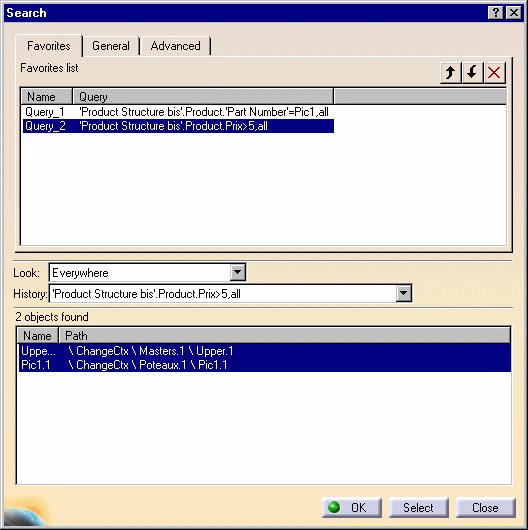
208 Page 208


209 Managing a Resource thanks to Resource Modeler Page 209 This task consists in managing Resources within the CATProduct's properties, thanks to the Resource Modeler framework available in CATIA Version 5. This is a means for the user to get information about the interfaces' methods and functions. You can create Resources within a CATProduct that is to say you can allot a particular behavior to the product. The product's behavior is therefore modified and adheres to new interfaces. Open the Assembly01.CATProduct document : 1. Select the icon Create a Resource in the Resource toolbar. The following dialog box is displayed: 2. Choose the Type of the Resource in the following list:

210 Page 210 And select the Category of the Resource : Physical or Organizational. 3. Click on OK. This message confirms the operation: You can either activate or deactivate the Resource description. If you click on the activate icon, you will have access to an existing Resource within the Product's Properties dialog box. There is additional information in the Properties dialog box, in the Resource tab. 4. Right-click the Product, select the Properties contextual command and the Properties dialog box appears. 5. Click on the More button in the Product's Properties dialog box and the Resource tab appears:
 and MTTR (Mean Time To Repair) parameters within this panel (Edit -> Properties command).")
211 Page 211 You can find precisions about the resource: the Product's name and the resource category. It is possible to specify the name, category and the MTBF (Mean Time Between Failure) and MTTR (Mean Time To Repair) parameters within this panel (Edit -> Properties command). These parameters are attributes for the resource. The access to the Resource properties activates the resource -whatever the status of the resource is: activated or deactivated- and shows its characteristics in a resource tab, in the propeties panel.
212 Page 212
213 Page 213 Product Structure Application Interoperability ENOVIA LCA Interoperability SmartBOM / CATIA V5 Interoperability
214 ENOVIA LCA Interoperability Page 214 Optimal CATIA PLM Usability for Product Structure Special Rules for Saving CATIA V5 Data into ENOVIA LCA Contextual Links Rules in CATIA V5 and ENOVIA LCA Workbench Breakdown Structure (WBS)
215 Optimal CATIA PLM Usability for Product Structure Page 215 The objective is to prevent the user from building / editing data in CATIA V5 if they cannot be saved in ENOVIA LCA. Therefore, in interoperability mode, some CATIA V5 commands are grayed out / hidden in the Product Structure workbench. Only commands subject to restrictions are listed below. And in some cases, rules are applied to restricted commands. Workbench Feature Command Accessibility in LCA mode Warning / Comment Save in LCA / Rules Inserting Existing Components YES / Only CATIA MultiCAD formats will be available. Replacing a Component YES / Only CATIA MultiCAD formats will be available. P R O D U C T S T R U C T U R E Product Structure Tools Reordering the Tree YES Accessible but all the transient data (in CATIA Session) will be lost in LCA; this notion does not exist in ENOVIA LCA. Special Rules for Saving CATIA V5 Data to ENOVIA LCA The Enovia Product Structure will not be ordered in exposed structure mode. Generating Numbers NO (grayed out) / / Defining Contextual Links YES Accessible but contextual links are not supported in some cases (known persistency problems). Rules to Check the Creation of Contextual Links Deactivating/Activating a Component NO (hidden) / / New CDM Component NO grayed out / / Move Using Flexible Sub-Products NO hidden / / Managing Representations YES Some data may be lost in some cases Some CATIA MultiCAD formats will not be available G E N E R I C C O M M A N D Representations WBS Generic commands (Generic tools) Special Rules for Saving CATIA V5 Data to ENOVIA LCA Save Activation State NO (grayed out) / / Delete WBS / This command is no / longer supported Editing Components YES Some data may be lost in some cases Paste will fail with error message explaining that it is not authorized Special Rules for Saving CATIA V5 Data to ENOVIA LCA Edit Product and Graphic Properties YES / Disable edition of not mapped properties
216 S Show/Hide YES Warning: all transient data are lost Page 216 /
217 Page 217 Special Rules for Saving CATIA V5 Data into ENOVIA LCA This task shows you special rules to be fulfilled in CATIA V5 before saving the Product in ENOVIA LCA. Commands applied to special rules The special rules applied to the following CATIA V5 commands are: Replace Component Manage Representations Copy/Cut/Paste Special Rules Here are the rules for these commands: A work package or a file CAN be mapped into a work package A work package or a file CAN be mapped into an exposed structure An exposed structure CAN be mapped into an exposed structure An exposed structure CANNOT be mapped into a work package or a file
218 Page 218 Rules to Check the Creation of Contextual Links This task explains you what are the Contextual Links constraints in CATIA V5, before saving the Product in ENOVIA LCA. Known Persistency Problems ENOVIA PRC exposes a sub-set of CATIA instances: Only under PRC Only for exposed references. ENOVIA contextual link is defined only on PRC instance. This is not mandatory for CATIA. CATIA does not make any different between workpackage and exposed references. Contextual link can be created either on instances "workpackage" or instances exposed or mixed. Contextual Link Rules Here are the rules to check the creation of the contextual link: If the persistency mode of the product reference of the context instance is different from the persistency mode of the product reference of the input instance then the contextual link CANNOT be created If the persistency mode of the root product that owns the context instance is a Work Package then the contextual link CAN be created If the root product that owns the context instance is the PRC and the persistency mode of the product reference of the context instance is exposed then the contextual link CAN be created In any other case the contextual link CANNOT be created CATIA / ENOVIA User View Here is a schema to explain the contextual links between ContextReference, InputReference and ContextFather:
219 Page 219
220 Work Breakdown Structure (WBS) Page 220 The V5 Product Structure model is based on the instance-reference model which meets assembly requirements. There is a second need of organizational nature. This is why this new functionality has been created: the insertion of new objects allowing data structuring and organization. The WBS functionality is only available in the context of the ENOVIA LCA/CATIA V5 interoperability. You can build a WBS persistent arborescence in a CATProduct and/or import an existing WBS arborescence into a CATProduct. One of the created views GCO (Generic component) can be designated as the active view and after the File/Open operation you immediately have access to the active view. You can associate the instance of a product to a GCO, with the following constraints: the instance must be a first instance (directly under the root product), and this instance can appear only once in a view. You can insert components, products, parts,... into a GCO node. These elements are under the root product, and an association between the created instance and the GCO node takes place. There are four navigation/visualization modes: Global View, Active View, Product Structure View and GCO View. In a V5 industrial Assembly, the first assembly levels are generally dedicated to organizational purposes whereas the other levels play the role of an assembly structure: In this schema, the red nodes correspond to the assembly structure whereas the blue ones represent the organizational role. You can now insert a new type of object: CATGco (blue nodes in the following schema). It allows you to improve the assembly model and bring flexibility in the organization data:

. You can also insert existing views.")
221 Page 221 The WBS arborescence has the following benefits: you can avoid the weight of the instance model when you do not need it there is no impact on the product architecture which has the same behavior there are several choices of views the product section is separated from the organizational part. You can modify the organizational part or the association of the organizational part with the product section without impacting on the product section. Open the TestWBS.CATProduct document. 1. Select the Root Product and click the contextual command: Add new view (to add a GCO). You can also insert existing views. The following dialog box appears and you can enter the name of the GCO:


222 Page Select a view and click the contextual command: Set Active View to visualize both GCO nodes and products. You can note that the Active View is always underlined: View1.


223 Page You can also Insert a new component / product / part, an existing component in the View. 4. There are four navigation/visualization modes available in the WBS toolbar. It is not active by default, you need to activate it from the View->Toolbar menu. Global View: complete Specification Tree, with the Product Structure and the WBS arborescence, which is useful to drag & drop components (see: screen shot above). Active View: GCO nodes and products. You can only visualize the products associated to the active view. You are in this mode after the File/Open operation. Product Structure View: the Specification Tree with the Product Structure, all the products can be visualized.. No access to the GCO nodes.
 and no product")

224 Page 224 View Tree: a tree with only the WBS arborescence (Views and GCO) and no product structure. 5. Click the contextual menu of a product, Part4 for instance, in GCO2 to remove it: And Part4 disappears:
225 Page 225
226 SmartBOM / CATIA V5 Interoperability Page 226 Export SmartBOM from CATIA V5
 is one of the most precious information shared between actors.")
227 Export SmartBOM from CATIA Version 5 Page 227 This task shows you how to export SmartBOM from CATIA Version 5. In Supply Chain environment or in Project management, the Bill of Material (BOM) is one of the most precious information shared between actors. Export of BOM Briefcase enables to share such data by means of nomad application (SmartBOM Editor from SmarTeam corporate). No specific installation is required to view and edit BOM. Install SmartBOM Product from the SmarTeam Corporate. 1. In order to set the environment data, select the Tools -> Options... command. The option dialog box appears with the category tree in the left-hand column. 2. In the General category of the options tree, select Compatibility and click the SmartBOM tab. The following dialog box appears. 3. Insert the User Name and address of you choice.
. This will enable you to browse the \"Install Path\".")
228 For the Export operation, Page Check the Embed associated documents box to attach CATIA documents (geometry and specifications) in Briefcase. 5. Check the Export Active Briefcase box, if you want to export BOM as a nomad application (.exe). This will enable you to browse the "Install Path". Install path is a temporary directory where the nomad application is built before being sent. For the Import operation, 6. Browse the temporary directory where imported package will be read. 7. Open a CATProduct document. 8. Save it as stbom file (or.exe file): select stbom or.exe as file format in the File/Save As dialog box.
. You can then send this data by e-mail or publish it on your Web site. 9.")
. 11.")
229 Page 229 This will generate the SmartBOM Briefcase (for instance: Landing_Gear_NewAssy.stbom) or SmartBOM Active Briefcase with your data (.exe file). You can then send this data by or publish it on your Web site. 9. Edit the stbom file in SmartBOM Editor: double-click the stbom file (or.exe file) to edit the BOM by using SmartBOM Product: 10. Save your changes by using SmartBOM Editor (File->Save as). 11. To import a new SmartBOM Briefcase in CATIA V5, select File->Open in CATIA V5 and choose the stbom format: the new BOM is imported with the attached CATIA documents.
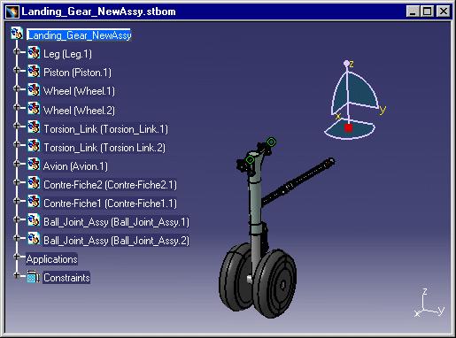
230 Page 230
231 Page 231

232 Workbench Description Page 232 The Product Structure Version 5 application window looks like this: Product Structure Menu Bar Product Structure Toolbar Specification Tree Symbols
233 Menu Bar Page 233 This section presents the main menu bar available when you run the application and before creating or opening a document: Start File Edit View Insert Tools Analyze Windows Help Edit For Replace Component... See Replacing a Component Isolate Part Isolating a Part Change Context Changing Context Load Loading Components Unload Unloading Components


234 Page 234 Graph tree Reordering Graph Tree Reordering Insert Manage Representations... Design Mode Visualization Mode Activate Node Deactivate Node Activate Terminal Node Deactivate Terminal Node For New Component New Product New CDM Component New Part Existing Component... Managing Representations Using Design Mode Using Visualization Mode Activating Node Deactivating Node Activating Terminal Node Deactivating Terminal Node See Inserting a New Component Inserting a New Product Adding a CDM Product to a Product, in ENOVIA/CATIA Interoperability User's Guide. Inserting a New Part Inserting an Existing Component
235 Page 235 Analyze Document Template Creation... For Bill of Material... CATIA - Product Knowledge Template User's Guide See Displaying the Bill of Material (BOM) Managing the Bill of Material (BOM) Capacity not to take into account a Component in BOM Searching on BOM Attributes
236 Product Structure Toolbar Page 236 See Inserting a New Component See Inserting a New Product See Inserting a New Part See Inserting an Existing Component See Replacing a Component See Reordering the Tree See Generating Numbers See Loading Components See Unloading Components Representation Toolbar See Managing Representations See Design Mode See Visualization Mode
237 Page 237 See Activate Node See Deactivate Node Resource Toolbar See Create a resource See Activate the Resource Description See Deactivate the Resource Description Workbench Breakdown Structure (WBS) Global View: complete Specification Tree, with the Product Structure and the WBS arborescence, which is useful to drag & drop components. Active View: GCO nodes and products. You can only visualize the products associated to the active view. You are in this mode after the File/Open operation. Product Structure View: the Specification Tree with the Product Structure, all the products can be visualized.. No access to the GCO nodes. View Tree: a tree with only the WBS arborescence (Views and GCO) and no product structure.
238 Customizing Page 238 Cache management CATIA / ENOVIA VPM Interoperability Nodes Customization Product Structure Product Visualization Tree Customization
239 Customizing Cache Settings Page 239 Working with a Cache System Two different modes are available when a component (V4 model, V5 CATPart, V5 CATProduct, etc.) is inserted into a DMU Navigator CATProduct document: Design mode: in this mode, the exact geometry is available and the document is inserted as is Visualization mode: in this mode, a representation of the geometry only is available and the corresponding cgr file, if it exists, is inserted from the cache system. Using a cache system considerably reduces the time required to load your data. The cache system is organized into two parts: Local cache: a read/write directory located locally on your machine and used to store cgr files. The first time a component is inserted, it is tesselated. This means that the corresponding cgr file is computed and saved in the local cache as well as displayed in the document window. The next time this component is required, the cgr file which already exists (and not the original document) is automatically loaded from the local cache. The user is normally responsible for the local cache. Released cache: a read-only cache that can be located anywhere on your network. Several directories can be defined for the released cache. If a cgr file cannot be found in the local cache, the software browses the released cache directories in their listed order to see if the cgr file is located in one of them. If the cgr file is still not found, the component is tesselated and the resulting cgr file is saved in the local cache. The site administrator is normally responsible for the released cache. A timestamp enables the verification that no modifications have been made to a document since the generation of the corresponding cgr file found in either of the above caches: Timestamp: the date and hour at which the origin document was last modified. If you activate the Check timestamp button, then before a cgr file is loaded into a viewer, its timestamp will be checked to verify that no modifications have been made to the document since the generation of the cgr file. If you don't activate the Check timestamp button, then a cgr file of a document will be loaded without any verification of its time-wise coherence with the document. The process used for loading data using the caches is as follows:
240 Page 240 The user requests the loading of a document into a viewer. The System searches for a corresponding tesselated file (cgr file) in the user's local cache. If found, then the timestamp is checked. If the timestamp of the cgr file is more recent than that of the document, then the cgr file is loaded into the viewer. If not, then the document is tesselated, the resulting cgr file is added to the user's local cache and the cgr file is loaded into the viewer. If not found, then the System searches for the corresponding tesselated file (cgr file) in the released cache. If found, then the timestamp is checked. If the timestamp of the cgr file is more recent than that of the document, then the cgr file is loaded into the viewer. If not, then the document is tesselated, the resulting cgr file overwrites the existing cgr file in the user's local cache and the cgr file is loaded into the viewer. If not found, then the document is tesselated and the resulting cgr file is added to the user's local cache and the cgr file is loaded into the viewer.
241 Page 241 Reading Components from a Database: The cache system works in exactly the same way when components inserted into a CATProduct document come from a database. An additional check is run: if the cgr file is not found in the local or released caches, the DMU Navigator requests that, if the cgr file exists in the database, it be downloaded. The cache system is managed via the Cache Management tab in the Options dialog box. All cache options can be locked. This task explains how to customize data cache settings. A DMU Navigator document must be opened. It is imperative that any directory designated for use as a cache directory be reserved for this usage only, i.e. you should not manually save any other files in this directory. (When necessary, the Check Maximum Size option purges the least-recently-accessed files in order to maintain the cache smaller than the designated Maximum size. As a result, any files that you manually save to this directory could eventually be purged.) When you are working in Cache mode, a.model or.catpart is converted to a.cgr format. You can convert the.cgr to a.model or.catpart format using the Design Mode command. See the task Design Mode in the Product Structure user guide. 1. Select the Tools -> Options... command. The Options dialog box appears. 2. Click Infrastructure -> Product Structure in the left-hand box. 3. Click the Cache Management tab.
 Cache Location New features have been added to the Cache Management that render the configuration of the local and released caches easier.")
242 Page 242 Cache Activation 4. To activate the cache, check the Work with the cache system checkbox. (By default, the cache is not activated.) Cache Location New features have been added to the Cache Management that render the configuration of the local and released caches easier. The new features are: Local cache - a history of the last five defined paths Released cache - a configuration panel that enables you to: select directories from a list of "accessible" directories that have been pre-defined by the administrator reorder directories list remove entries from the directories list
243 Page 243 Note that it is possible to use environment variables to define a local cache or a released cache: the variable should be defined (using the set command on Windows NT or the export command on UNIX) in the script file used to launch the executable file of the interactive application the variable must be correctly valuated to an existing directory the entry in the local cache or released cache text-entry field should be of the form ${variable_name} 5. To define a local cache directory, enter the name of the directory in the Path to the local cache text-entry field or click the Path to the local cache selection button and select an entry from the proposed history list. 6. To define a released cache directory, enter the name of the directory in the Path to the local cache textentry field or invoke the released cache configuration panel by clicking the Path to the released cache Configure button. The Configuration panel appears. 7. To add one of the Accessible Directories to the list of Current Directories, select the entry in the Accessible Directories list and click the Right-arrow icon. The entry is added to the Current Directories list. Note: The list of directories in the Accessible Directories list is defined by the administrator as follows: define a.txt file of which each line contains the path to a directory that will appear in the list of accessible directories set and export an environment variable AVAILABLE_CACHE_DIR_PATH that points to the above.txt file the administrator can, of course, manage the access rights to the above-defined directories so as to restrict their access to groups of users or specific users
, select")
244 Page To move one of the entries in the Current Directories list to a higher place in the list (remember that released cache directories are searched in the order in which you see them displayed), select the entry in the Current Directories list and click the Up-arrow icon. The entry is moved up in the list. 9. To delete an entry from the Current Directories list, select the entry in the Current Directories list and click the Delete button.
245 10. (Optional) Enter the paths identifying the cache locations: Page 245 The Browse icon enables you to locate the file you want. The user can enter the path to his own local cache location, and if permitted by the site administrator, one or more paths to released cache locations. The default directory is the user's home directory under UNIX and the USERPROFILE directory under Windows. Cache Size 11. (Optional) Set the maximum size for the local cache (in write mode). When the maximum size is exceeded, the automatic deletion of.cgr files (on a first-in / first-out basis) is triggered. The default maximum size is 500 MB. 12. (Optional) Set the Check maximum size option: When creating new cgr files in the cache, the check maximum size option serves to purge the oldest cgr files if necessary in order to respect the defined maximum cache size. If the option is activated, the check and eventual purge will be performed. If the option is not activated, the check will not be performed. Timestamp 13. (Optional) Set the Check timestamp option: The timestamp option serves to check whether or not the tessellated cgr file is up-to-date. If clicked, the system checks the original document's date against that of the corresponding cgr file, and if older, tessellates the document again overwriting the out-of-date version. If dates are the same, no tessellation is done and the cgr file in the data cache is loaded. Turning this option off means that no check is run and cgr files in the cache are systematically loaded.
246 Page 246 Until now, the cache timestamp has been based on local time. This can lead to unwanted re-tessellations if you are sharing data between sites located in different time zones. It is now possible to base your cache on GMT time. The following are the rules for implementing your cache based on GMT time: a batch job will permit you to migrate old caches to GMT time-based caches once a cache is migrated to or designated as GMT time-based, you can never go back to a local time-based cache ALL caches (local cache and released caches) must be of the same format To migrate an old cache, use the following command: CATSysMvCache -o UTC -inputdir input_directory -log file.txt [-outputdir output_directory] If outputdir is not set, the cache specified in inputdir and the documents it contains are converted to GMT format. Once a cache has been migrated to GMT time-based, it is no longer compatible with previous releases of ENOVIA DMU or CATIA (i.e. a migrated cache cannot be used in V5R11 or below). 14. Check the GMT timestamp format checkbox to designate all caches specified in Cache Location as GMT time-based. Note: When the GMT timestamp format option is activated: all new caches will be based on GMT time all specified caches must have been updated using the provided batch job If any of the caches specified do not conform to the rule that all caches must be of the same format, an error message will appear. Cache Content When working in visualization mode, the insert component of a CATProduct will generate in the cache a cgr containing Levels of Detail (Lods). This option is activated by default. 15. To deactivate the Generate cgr with level of detail option, click the corresponding checkbox. 16. When you've finished defining the different options, click OK to confirm.

247 Page 247 Customizing CATIA/ENOVIAVPM Interoperability Settings This task shows you how to customize ENOVIAVPM settings. 1. Select the Tools->Options... command. When it appears, select the Infrastructure- >Product Structure category in the tree on the left. 2. Click on the ENOVIAvpm tab. The following dialog box appears: As you can see, the Options dialog box is divided into four parts: CDM Interoperability Administration PSN Display Options Customize Session Building V4 CDM Cache Management CDMA Interoperability Administration There are three pushbuttons in this part:
248 Page 248 Selecting the Database Administration button lets you define the parameters for connection to the CDMA databases you wish to use (see "Connecting an ORACLE or DB2 Database to Your CATIA Version 5 Environment" in the ENOVIAVPM User's Guide). Checking the Database Server Dictionary box lets you define a CDMA dictionary associated with a server. Checking the ENOVIAvpm/Product Structure Mapping box lets you map CDMA and assembly attributes (see "Mapping CDMA and Assembly Attributes" in the ENOVIAVPM User's Guide). PSN Display Options There is one checkbox in this part: Checking the Automatic Highlight in PSN box sets the automatic highlight for the identification of models in a PSN graph from a Version 5 session and vice-versa. This means that whenever you select one or more models in a PSN graph they are automatically highlighted in the Version 5 session. When selected in a Version 5 session, they are automatically highlighted in the corresponding PSN graph. If you do decide to use this option you should be aware that performance will be adversely affected. Customize Session Building There are two checkboxes in this part: Checking the Load all EnoviaVPM properties box means that when a session is built all the properties visualized in VPM that have not been mapped will be loaded as user properties. If you do decide to use this option you should be aware that performance will be adversely affected. Checking the Disable Applicative Object management box speeds up performance. If you do decide to use this option you should be aware that V5 applicative objects such as publications, constraints, etc. will neither be saved nor stored in the database. V4 CDM Cache Management There is one checkbox in this part: Checking the Work with the V4 CDM cache system box enables you to use the cache system and provide the location of the V4 local cache in the field CDM Cache path. You can also specify the access method in the field Access method.

249 Nodes Customization Page 249 This task shows you how to give a particular name, reference or description to a product or a component. 1. Select the Tools->Options->Infrastructure->Product Structure command and click the Nodes Customization tab. Check the option Customized Display and the settings become active. 2. Check Customized Display. Then, you can select different options: Part number (#PN#), Revision (#RE#), Definition, Nomenclature, Source, Instance Name, Description. You can directly replace the diagram (PN, RE,...) between the two # by the term of your choice and it will appear in the Product Structure. By the same way, you can add a comma and a blank space between these parameter.

250 Page 250 If you are using CATIA "with cache system", many informations that you can usually display on each node are not available for the CATPart nodes when opening a CATProduct. In this case, the unavailable information is replaced by the character string '[?]'. There is one exception : the "Part Number" (#PN#) which is replaced by '[NNNN]' where NNNN is the name of the file containing the CATPart (without the directory name). Those unavailable informations are made available when you use the "Properties" command on a CATPart. At this moment, the '[?]' strings are replaced by the real values for this particular node in the specification tree. 3. These attributes are also accessible in the component's contextual menu: Edit->Properties. For instance, open the following example ManagingComponents01.CATProduct and select the Edit- >Properties contextual command of CRIC_AXIS.CATPart. For more information about Component Properties, please refer to Modifying Component Properties in CATIA - Product Structure User's Guide. 4. Click the Define other properties button to add new attributes to CRIC-AXIS.CATPart and click the New Parameter of type button. The following dialog box appears: You can add the "Price" parameter in the Edit name and value field:
251 Page 251 And you can notice the modifications in the Properties dialog box:

252 Page Click OK. 6. Select the Tools->Options->Infrastructure->Product Structure command and the Nodes Customization tab. Check the option Customized Display and choose the following settings:
253 To specify the Price parameter, you need to use these characters: Page Click OK. And you obtain in the following result in the Specification Tree:

254 Customizing Product Structure Settings Page 254 This task explains how to customize Product Structure settings. 1. Select the Tools->Options... command. 2. Select the Infrastructure category, then the Product Structure sub-category, then the Product Structure tab: Defining the Default Part Number of the Component to be Imported Check Manual input if you wish to assign the name you wish to the component you insert into the assembly. Selecting the Low Light Mode of the component that does not belong to the active level If you check the Low Light Mode option and select (double-click) a component in a CATProduct, it becomes UI Active (highlighted) in the Geometry Space:
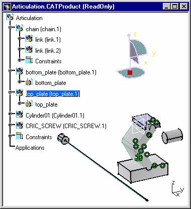
255 Page 255
256 Page 256 The second example shows that the operation is also possible with Models. This is a visualization mode : the selected element remains highlighted and the other geometric components are in low light (gray-colored). If you double-click on another element, it immediately becomes highlighted and the other ones are grayed. Describing the model file in the Bill Of Material Select the Model In BOM option in order to have access the Models' information (path name for instance) in the document's BOM. 1. Open a CATIA document containing one or several models. 2. Select the Analyze -> Bill Of Material Menu and click the Listing Report tab.

257 Page Click on the Refresh button in order to access to the components' properties (path name for example):

258 Page 258 These Models have been inserted into a CATProduct and you can now visualize the Models' path name. You can find the original directories in which the models were stored. When there is a broken link, you can read the following expression : "Unretrieved document". Reframe Mode after insert existing component Check the Reframe Mode options you need: In the following examples, CRIC_FRAME.1 has been inserted into Product6 and a different Reframe Mode has been selected beforehand. The original CATProduct looks like this: Global Reframe: this is the default value, Global Reframe zooms on the whole geometry and it allows you to see all the components. After the insertion of CRIC_FRAME.1 into Product6, the visualization of the geometry is readjusted in CATIA window so that all the components can be seen.


259 Page 259 No Reframe: if you insert an element in the product, you may not see the totality of this element in the CATIA window. The visualization on the already existing component, CRIC_AXIS.1, does not change. There is no Reframe on the last inserted element. Reframe on last inserted component: This zoom-in capability improves the visualization of the last inserted component. Therefore, in some cases, you cannot visualize the other CATIA objects because there is an automatic Reframe on the last inserted component.


260 Page 260 Customizing the Specification Tree Products to display the products in the Specification Tree. When the option is activated: When the option is deactivated: To display the Constraints, Parameters and Relations, you need go to the Tree Customization tab. To modify the setting Automatic expand, you need to select the Tools->Options->General->Display category and the Tree tab: 3. Click OK to confirm.


261 Customizing Product Visualization Settings Page 261 This task explains how to customize Product Visualization settings. 1. Select the Tools->Options... command. 2. Select the Infrastructure category, then the Product Structure sub-category, then the Product Visualization tab: Representation In the "Representation" area, if you click the "Do not activate shapes on open" selection box, the graphical representations of all the components will not be computed when opening a CATProduct. So the only thing that will be displayed is the specification tree. This option may be used to speed up the opening of large CATPRoducts when you don't need to see all the components. Once the CATProduct is opened, you can display the component you need to see by using the Representation -> Activate Node option in the contextual menu of these components. Visualization Mode Type Visualization Mode with local cache: option by default, when the Cache is activated (check the Work with the cache system checkbox). In this case you create all the cgr files in a local cache in mono process. Multi Process Visualization Mode with local cache: when the Cache is activated. You can choose the creation of Cache files in multi process (DMU context). If you decide to check "Multi Process Visualization Mode with local cache" rather than "Visualization Mode with local cache", the following message appears:

262 Page 262 Visualization Mode without local cache: the cgr files within local Cache cannot be visualized; they are not created in the local cache. None: when this option is activated, you are not in Visualization Mode but in Design Mode. 3. Click OK to confirm.

263 Tree Customization Page 263 This task explains how to customize Product Structure settings. 1. Select the Tools->Options... command. 2. Select the Infrastructure category, then the Product Structure sub-category, then the Tree Customization tab: In the Specification Tree Order category, there is a list of CATIA attributes corresponding to the nodes in the Specification Tree. This list allows you to order nodes in the Specification Tree and to activate or deactivate their visualization. This is an order by default. You can modify this order by selecting a Specification Tree Node Name and clicking the Up or Down button. You can reorder the whole structure, for instance:

264 Page Click OK and the option panel is closed. The result in the Specification Tree corresponds to the order you had customized in the setting, for instance: The column entitled Activated allows you to activate or deactivate one or several nodes in the Specification Tree. For instance, you can choose to deactivate the Constraints node: And you obtain:
 in the Specification Tree, you can activate the corresponding nodes: You can deactivate")
265 Page 265 Products and Publication Nodes cannot be deactivated. If you add a new node (for instance, a Material: Concrete) in the Specification Tree, you can activate the corresponding nodes: You can deactivate this component by the same way: Or reorder the components within the Specification Tree:

266 Page 266 And you obtain:
Electrical 3D Design & Documentation
 Electrical 3D Design & Documentation Page 1 Overview Conventions User Tasks Using Electrical 3D Design & Documentation Entering the Electrical Assembly Design Workbench Entering the Electrical Part Design
Electrical Wire Routing
 Electrical Wire Routing Page 1 Overview Conventions What's New? Getting Started Accessing the Workbench Creating the Bundle Selecting Systems with External Data Routing Wires from External Data User Tasks
Electrical Harness Installation
 Electrical Harness Installation Page 1 Overview Conventions What's New? Getting Started Entering the Workbench Setting Up the Options Creating a Bundle Segment Document Creating Construction Points Defining
DMU Space Engineering Assistant User Guide
 DMU Space Engineering Assistant User Guide Overview Conventions What's New? Getting Started User Tasks Setting Up Your Session Running an Interference Analysis Workbench Description DMU Space Engineering
DMU Space Engineering Assistant User Guide
 Page 1 DMU Space Engineering Assistant User Guide Overview Conventions What's New? Getting Started User Tasks Setting Up Your Session Running a Interference Workbench Description DMU Space Engineering
Electrical Harness Flattening
 Electrical Harness Flattening Overview Conventions What's New? Getting Started Accessing the Electrical Harness Flattening Workbench Defining the Harness Flattening Parameters Extracting Data Flattening
Electrical System Functional Definition
 Electrical System Functional Definition Overview Conventions What's New? Getting Started Creating a New System Creating Equipment Creating Connectors Creating a Signal Connecting Saving Your System User
Electrical System Functional Definition
 Electrical System Functional Definition Preface What's New? Getting Started Basic Tasks Advanced Tasks Workbench Description Customizing Glossary Index Dassault Systèmes 1994-2000. All rights reserved.
Equipment Support Structures
 Equipment Support Structures Overview Conventions What's New? Getting Started Setting Up Your Session Creating a Simple Structural Frame Creating Non-uniform Columns Creating Plates with Openings Bracing
Equipment Support Structures
 Page 1 Equipment Support Structures Preface Using This Guide Where to Find More Information Conventions What's New? Getting Started Setting Up Your Session Creating a Simple Structural Frame Creating Non-uniform
DMU Engineering Analysis Review
 Page 1 DMU Engineering Analysis Review Preface Using This Guide Where to Find More Information Conventions What's New? Getting Started Inserting a CATAnalysis Document Using DMU Space Analysis From CATAnalysis
Electrical Library Version 5 Release 13. Electrical Library
 Electrical Library Page 1 Overview Conventions What's New? Getting Started Entering the Electrical Part Design Workbench Defining a Single Insert Connector Defining a Cavity Connection Point Entering Electrical
DMU Engineering Analysis Review
 DMU Engineering Analysis Review Overview Conventions What's New? Getting Started Entering DMU Engineering Analysis Review Workbench Generating an Image Visualizing Extrema Generating a Basic Analysis Report
Fastening Review Overview Basic Tasks DMU Fastening Review Interoperability Workbench Description Customizing Index
 Fastening Review Overview Conventions Basic Tasks Displaying Joined Parts in a Balloon Running the Fastening Rules Analysis Reporting Creating Structural Reports Creating Flat Reports DMU Fastening Review
Tolerance Analysis of Deformable Assembly
 Tolerance Analysis of Deformable Assembly Overview Conventions What's New? Getting Started Entering the Workbench Creating a New Analysis Importing the Assembly Definition Computing a Tolerance Analysis
Circuit Board Design Version 5 Release 13. Circuit Board Design
 Circuit Board Design Page 1 Overview Conventions What's New? Getting Started Accessing the Circuit Board Workbench Creating a Board Pocket and Holes Constraint Area Exporting Data Importing Data User Tasks
DMU Space Analysis Version 5 Release 13. DMU Space Analysis
 Page 1 DMU Space Analysis Preface Using This Guide More Information Conventions What's New? Getting Started Setting Up Your Session Measuring Minimum Distances Sectioning Detecting Clashes Measuring Between
DMU Optimizer Overview What's New? Getting Started User Tasks
 DMU Optimizer Overview Conventions What's New? Getting Started Starting a Session Generating a Silhouette Generating a Wrapping Generating a Thickness Generating an Offset Generating a Free Space User
Structure Preliminary Layout
 Structure Preliminary Layout Overview Conventions What's New? Getting Started Setting Up Your Session Defining the Hull Form Setting Up Your Grid Creating Molded Forms Creating a Compartment Creating Boundaries
NC Manufacturing Verification
 NC Manufacturing Verification Overview Conventions What's New? User Tasks Accessing NC Manufacturing Verification Comparing the Machined Stock Part and the Design Part Pick Point Analysis in Video Mode
DMU Fitting Simulator
 Page 1 DMU Fitting Simulator Preface Using This Guide More Information Conventions What's New? Getting Started Using Tracks Starting a Session Recording a Track Using Automatic Path Finder Using the Smooth
Structure Preliminary Layout
 Page 1 Structure Preliminary Layout Preface Using This Guide Where to Find More Information What's New? Getting Started Setting Up Your Session Defining the Hull Form Setting Up Your Grid Creating Molded
NC Manufacturing Verification
 NC Manufacturing Verification Page 1 Preface Using This Guide Where to Find More Information Conventions What's New? User Tasks Accessing NC Manufacturing Verification Comparing the Machined Stock Part
Advanced Meshing Tools
 Page 1 Advanced Meshing Tools Preface Using This Guide More Information Conventions What's New? Getting Started Entering the Advanced Meshing Tools Workbench Defining the Surface Mesh Parameters Setting
Knowledge Expert Overview What's New? Getting Started Basic Tasks Advanced Tasks Reference
 Knowledge Expert Overview Conventions What's New? Getting Started Creating an Expert Check Creating an Expert Rule Basic Tasks About RuleBases Storing a Rule Base in a Catalog Using a Rule Base Stored
Compartment and Access
 Compartment and Access Preface Using This Guide What's New? Getting Started Entering the Workbench Set Correct Working Units and Grid Saving Documents User Tasks Creating/Modifying Wall Systems Building
Mechanical Design V5R19 Update
 CATIA V5 Training Foils Mechanical Design V5R19 Update Version 5 Release 19 August 2008 EDU_CAT_EN_MD2_UF_V5R19 1 About this course Objectives of the course Upon completion of this course you will be able
Prismatic Machining Overview What's New Getting Started User Tasks
 Prismatic Machining Overview Conventions What's New Getting Started Enter the Workbench Create a Pocketing Operation Replay the Toolpath Create a Profile Contouring Operation Create a Drilling Operation
Compartment and Access
 Compartment and Access Page 1 Preface Using This Guide What's New? Getting Started Entering the Workbench Set Correct Working Units and Grid Saving Documents User Tasks Creating/Modifying Wall Systems
Preface. Version 5 Release 5. Mold Tooling Design
 Version 5 Release 5 Mold Tooling Design Preface Getting Started Basic Tasks Advanced Tasks Customization Workbench Description Glossary Index Preface The CATIA Version 5 Mold Tooling Design application
CATIA Teamcenter Interface RII
 CATIA Teamcenter Interface RII CMI RII Release 3.1 User Manual Copyright 1999, 2011 T-Systems International GmbH. All rights reserved. Printed in Germany. Contact T-Systems International GmbH PDC PLM Fasanenweg
CATIA Teamcenter Interface RII
 CATIA Teamcenter Interface RII CMI RII Release 2.2 User Manual Copyright 1999, 2010 T-Systems International GmbH. All rights reserved. Printed in Germany. Contact T-Systems International GmbH Solution
Piping & Instrumentation Diagrams
 Piping & Instrumentation Diagrams Preface Using This Guide What's New? Getting Started Entering the Workbench Setting up Working Units and Grid Placing Components Routing a Piping Line or I & C Loop Placing
Aerospace Sheetmetal Design
 Aerospace Sheetmetal Design Page 1 Overview Conventions What's New? Getting Started Entering the Aerospace SheetMetal Design Workbench Defining the Aerospace SheetMetal Parameters Creating a Web from a
Knowledge Advisor Overview What's New? Getting Started User Tasks
 Knowledge Advisor Overview Conventions What's New? Getting Started Using Parameters Using Formulas Using Rules Using Checks User Tasks Working with Parameters Creating a Parameter Introducing Parameters
Systems Space Reservation
 Systems Space Reservation Preface Using This Guide What's New? Getting Started Enter the Workbench Create an Equipment Reservation Set Correct Working Units and Grid Changing the Current Axis Saving Documents
MULTICAx SE Plug-in Overview What's New? User Tasks Customizing Index
 MULTICAx SE Plug-in Overview What's New? User Tasks Requirements Methodologies and Advice Initializing the Environment Importing Data Importing Part Files Interactively 3d com Interoperability:Importing
MULTICAx UD Plug-in Overview What's New? User Tasks Customizing Glossary Index
 MULTICAx UD Plug-in Overview What's New? User Tasks Requirements Methodologies and Advice Initializing the Environment Initializing the Environment for Indirect Mode Initializing the Environment for Direct
CHAPTER 1 COPYRIGHTED MATERIAL. Finding Your Way in the Inventor Interface
 CHAPTER 1 Finding Your Way in the Inventor Interface COPYRIGHTED MATERIAL Understanding Inventor s interface behavior Opening existing files Creating new files Modifying the look and feel of Inventor Managing
HVAC Diagrams Preface What's New? Getting Started User Tasks
 HVAC Diagrams Preface Using This Guide What's New? Getting Started Entering the Workbench Setting up Working Units and Grid Placing Components Routing an HVAC Line Placing Components in a Line Repositioning
MULTICAx PD Plug-in Overview What's New? User Tasks Customizing Glossary Index
 MULTICAx PD Plug-in Overview What's New? User Tasks Requirements Methodologies and Advice Initializing the Environment Initializing the Environment for Indirect Mode Initializing the Environment for Direct
CATIA Teamcenter Interface
 CATIA Teamcenter Interface CMI Release 10.11 User Manual Copyright 1999, 2018 T-Systems International GmbH. All rights reserved. Printed in Germany. Contact T-Systems International GmbH GDC Product Lifecycle
Piping & Instrumentation Diagrams
 Page 1 Piping & Instrumentation Diagrams Preface Using This Guide What's New? Getting Started Entering the Workbench Setting up Working Units and Grid Placing Components Routing a Piping Line or I & C
Getting Started. These tasks should take about 20 minutes to complete. Getting Started
 Getting Started Getting Started This tutorial will guide you step-by-step through your first ELFINI and Generative Part Structural Analysis session, allowing you to get acquainted with the product. You
Piping Design. Site Map Preface Getting Started Basic Tasks Advanced Tasks Customizing Workbench Description Index
 Piping Design Site Map Preface Getting Started Basic Tasks Advanced Tasks Customizing Workbench Description Index Dassault Systèmes 1994-2001. All rights reserved. Site Map Piping Design member member
FreeStyle Shaper & Optimizer
 FreeStyle Shaper & Optimizer Preface What's New Getting Started Basic Tasks Advanced Tasks Workbench Description Customizing Glossary Index Dassault Systèmes 1994-99. All rights reserved. Preface CATIA
WINDOWS NT BASICS
 WINDOWS NT BASICS 9.30.99 Windows NT Basics ABOUT UNIVERSITY TECHNOLOGY TRAINING CENTER The University Technology Training Center (UTTC) provides computer training services with a focus on helping University
Knowledge Expert Version 5 Release 13. Knowledge Expert
 Knowledge Expert Page 1 Preface Using this Guide What's New? Getting Started Basic Tasks About RuleBases Storing a Rule Base in a Catalog Using a Rule Base Stored in a Catalog Importing a Rule Base Activating
전산응용설계 (Computer Aided Design)
") 전산응용설계 (Computer Aided Design) CATIA (Computer Aided Three dimensional Interactive Application) 기계자동차공학부자동차공학전공 Chapter 3. CATIA 기초 학습내용 : 객체선택 (Selecting Objects) 객체감추기와보이기 (Hiding and Showing objects)
전산응용설계 (Computer Aided Design) CATIA (Computer Aided Three dimensional Interactive Application) 기계자동차공학부자동차공학전공 Chapter 3. CATIA 기초 학습내용 : 객체선택 (Selecting Objects) 객체감추기와보이기 (Hiding and Showing objects)
Structure Design Administration
 CATIA V5 Training Exercises Structure Design Administration Version 5 Release 19 January 2009 EDU_CAT_EN_SRA_AX_V5R19 1 Table of Contents Step 1: Creating a New Project 3 Do It Yourself 4 Step 2: Adding
MULTICAx STEP Plug-in
 MULTICAx STEP Plug-in Overview What's New User Tasks Requirements Methodologies and Advice Initializing the Environment Importing STEP Data Importing Part Files Interactively Translating Files from the
SheetMetal Design Version 5 Release 13. SheetMetal Design
 SheetMetal Design Page 1 Overview Conventions What's New? Getting Started Entering the Workbench Defining the Parameters Creating the First Wall Creating the Side Walls Creating a Cutout Creating Automatic
Schematics in ArcMap Tutorial
 Schematics in ArcMap Tutorial Copyright 1995-2010 Esri All rights reserved. Table of Contents Introducing Schematics in ArcMap Tutorial........................ 3 Exercise 1: Getting familiar with Schematics
MULTICAx SolidWorks Plug-in
 MULTICAx SolidWorks Plug-in Overview What's New? User Tasks Requirements Methodologies and Advice Initializing the Environment Importing SolidWorks Data Importing Part Files or Assembly Files Interactively
AutoCAD 2009 User InterfaceChapter1:
 AutoCAD 2009 User InterfaceChapter1: Chapter 1 The AutoCAD 2009 interface has been enhanced to make AutoCAD even easier to use, while making as much screen space available as possible. In this chapter,
Policy Commander Console Guide - Published February, 2012
 Policy Commander Console Guide - Published February, 2012 This publication could include technical inaccuracies or typographical errors. Changes are periodically made to the information herein; these changes
FreeStyle Shaper Optimizer & Profiler
 FreeStyle Shaper Optimizer & Profiler Page 1 Preface Using This Guide More Information What's New? Getting Started Starting the FreeStyle Workbench Creating a First Surface Editing the Surface Creating
SAP Engineering Control
 SAP Engineering Control Center Interface to CATIA V5 User Documentation 01.02.2016 CENIT AG Software Product / Components: Product Version: 1.1.5 Creation Date: 28.08.2015 16:27 Document Version: 8 Last
Quick Start Guide. ARIS Architect. Version 9.8 Service Release 2
 ARIS Architect Version 9.8 Service Release 2 October 2015 This document applies to ARIS Version 9.8 and to all subsequent releases. Specifications contained herein are subject to change and these changes
Using Open Workbench Version 1.1
 Version 1.1 Second Edition Title and Publication Number Title: Edition: Second Edition Printed: May 4, 2005 Copyright Copyright 1998-2005 Niku Corporation and third parties. All rights reserved. Trademarks
MindView Online - Quick Start Guide
 MindView Online - Quick Start Guide Overview MindView Online is an online concept mapping program that allows users to organize their thoughts visually to create, share, and export mind maps to Microsoft
2 Getting Started. Getting Started (v1.8.6) 3/5/2007
 3/5/2007") 2 Getting Started Java will be used in the examples in this section; however, the information applies to all supported languages for which you have installed a compiler (e.g., Ada, C, C++, Java) unless
2 Getting Started Java will be used in the examples in this section; however, the information applies to all supported languages for which you have installed a compiler (e.g., Ada, C, C++, Java) unless
SAP Engineering Control
 SAP Engineering Control Center Interface to CATIA V5 User Documentation 01.02.2016 CENIT AG Software Product / Components: Product Version: 1.1.4 Creation Date: 28.08.2015 16:27 Document Version: 5 Last
NiceForm User Guide. English Edition. Rev Euro Plus d.o.o. & Niceware International LLC All rights reserved.
 www.nicelabel.com, info@nicelabel.com English Edition Rev-0910 2009 Euro Plus d.o.o. & Niceware International LLC All rights reserved. www.nicelabel.com Head Office Euro Plus d.o.o. Ulica Lojzeta Hrovata
SIEMENS. Modeling assemblies. Self-Paced Training. spse01540
 SIEMENS Modeling assemblies Self-Paced Training spse01540 Proprietary and restricted rights notice This software and related documentation are proprietary to Siemens Product Lifecycle Management Software
xcompare V5/V5 2.1.x Quick Start Guide
 xcompare V5/V5 2.1.x Quick Start Guide This guide helps you getting started with comparing documents with xcompare V5/V5 and analyzing their differences. Basics xcompare recognizes differences between
for Q-CHECKER Text version 15-Feb-16 4:49 PM
 Q-MONITOR 5.4.X FOR V5 for Q-CHECKER USERS GUIDE Text version 15-Feb-16 4:49 PM Orientation Symbols used in the manual For better orientation in the manual the following symbols are used: Warning symbol
Function. Description
 Function Check In Get / Checkout Description Checking in a file uploads the file from the user s hard drive into the vault and creates a new file version with any changes to the file that have been saved.
Service Minder Plus Features/Helpful Hints
 Service Minder Plus Features/Helpful Hints This manual covers helpful hints and use of features. Note: These items will be addressed during the training sessions. This document is meant to be used as an
Copyright 2018 MakeUseOf. All Rights Reserved.
 15 Power User Tips for Tabs in Firefox 57 Quantum Written by Lori Kaufman Published March 2018. Read the original article here: https://www.makeuseof.com/tag/firefox-tabs-tips/ This ebook is the intellectual
for ArcSketch Version 1.1 ArcSketch is a sample extension to ArcGIS. It works with ArcGIS 9.1
 ArcSketch User Guide for ArcSketch Version 1.1 ArcSketch is a sample extension to ArcGIS. It works with ArcGIS 9.1 ArcSketch allows the user to quickly create, or sketch, features in ArcMap using easy-to-use
Layout and display. STILOG IST, all rights reserved
 2 Table of Contents I. Main Window... 1 1. DEFINITION... 1 2. LIST OF WINDOW ELEMENTS... 1 Quick Access Bar... 1 Menu Bar... 1 Windows... 2 Status bar... 2 Pop-up menu... 4 II. Menu Bar... 5 1. DEFINITION...
Introduction to Windows
 Introduction to Windows Naturally, if you have downloaded this document, you will already be to some extent anyway familiar with Windows. If so you can skip the first couple of pages and move on to the
Tetra4D Reviewer. Version 2018 User Guide. Document version: V3.0. Tetra4D Reviewer 2018 Users Guide V3.0 1
 Tetra4D Reviewer Version 2018 User Guide Document version: V3.0 Tetra4D Reviewer 2018 Users Guide V3.0 1 Table of Contents Chapter 1: Tetra4D Reviewer overview... 4 Tetra4D Reviewer application... 4 Tetra4D
Electrical Cableway Routing
 Electrical Cableway Routing Preface Using This Guide What's New? Getting Started Entering the Workbench Placing a Hanger Routing a Loft Through Hangers Placing a Conduit on a Run Saving Documents Updating
Figure 1: Edit/ Links panel showing 5 import links but only one context link
 Tips and Techniques Links in CATIA, Part 3: Context Link Julie Cyrenne, Dassault Systemes Introduction In the previous article, we saw how to do design in context, where the child part (also known as contextual
ICS Tutorials: Basic Operations
 ICS Tutorials: Basic Operations This tutorial introduces the basic components of Builder Xcessory. For more detailed information, see the Builder Xcessory Reference Manual. This book is directly accessible
IBM Rational Rhapsody Gateway Add On. User Manual
 User Manual Rhapsody IBM Rational Rhapsody Gateway Add On User Manual License Agreement No part of this publication may be reproduced, transmitted, stored in a retrieval system, nor translated into any
How to Get Started. Figure 3
 Tutorial PSpice How to Get Started To start a simulation, begin by going to the Start button on the Windows toolbar, then select Engineering Tools, then OrCAD Demo. From now on the document menu selection
Human Posture Analysis
 Human Posture Analysis Overview Conventions What's New? Getting Started Creating a Manikin User Tasks Using the Posture Editor Selecting or Editing the DOF (Degree of Freedom) Displaying and Editing Angular
IBM Rational Rhapsody Gateway Add On. User Guide
 User Guide Rhapsody IBM Rational Rhapsody Gateway Add On User Guide License Agreement No part of this publication may be reproduced, transmitted, stored in a retrieval system, nor translated into any
Lesson 1: Getting Familiar with Microsoft Word 2007 for Windows
 Lesson 1: Getting Familiar with Microsoft Word 2007 for Windows Microsoft Word is a word processing software package. You can use it to type letters, reports, and other documents. This tutorial teaches
Learning the Pro/ENGINEER Interface
 2 Learning the Pro/ENGINEER Interface This chapter introduces the Pro/ENGINEER interface tools: the menus, the dashboards, the selection tools and the viewing controls. As you go through this chapter,
Getting Started (1.8.7) 9/2/2009
 9/2/2009") 2 Getting Started For the examples in this section, Microsoft Windows and Java will be used. However, much of the information applies to other operating systems and supported languages for which you have
2 Getting Started For the examples in this section, Microsoft Windows and Java will be used. However, much of the information applies to other operating systems and supported languages for which you have
FEM Surface. Preface Getting Started Basic Tasks Glossary Index TOC. Dassault Systèmes All rights reserved.
 TOC FEM Surface Preface Getting Started Basic Tasks Glossary Index Dassault Systèmes 1994-99. All rights reserved. file:////moyenne/users/cma/fmsdoccxr5/fmsenglish/fmsug.doc/src/fmsugtoc.htm [09/26/2000
Quick Start Guide. ARIS Architect. Version 9.7
 ARIS Architect Version 9.7 October 2014 This document applies to ARIS Version 9.7 and to all subsequent releases. Specifications contained herein are subject to change and these changes will be reported
Windows Me Navigating
 LAB PROCEDURE 11 Windows Me Navigating OBJECTIVES 1. Explore the Start menu. 2. Start an application. 3. Multi-task between applications. 4. Moving folders and files around. 5. Use Control Panel settings.
Tetra4D Reviewer. Version 5.1. User Guide. Details on how to use Tetra4D Reviewer.
 Tetra4D Reviewer Version 5.1 User Guide Details on how to use Tetra4D Reviewer. ii Contents Chapter 1: Work area... 7 Looking at the work area... 7 Toolbars and toolbar presets... 8 About toolbars and
ORGANIZING YOUR ARTWORK WITH LAYERS
 9 ORGANIZING YOUR ARTWORK WITH LAYERS Lesson overview In this lesson, you ll learn how to do the following: Work with the Layers panel. Create, rearrange, and lock layers and sublayers. Move objects between
Introduction to SAP. Navigation Module
 Introduction to SAP Navigation Module October 2009 Contents 1 Introduction to SAP... 3 1.1 Log On... 3 1.2 Navigation Through SAP... 5 1.3 The Menu Bar... 5 1.4 The Short Cut Toolbar... 6 1.5 Display Technical
Introduction to Microsoft Office 2016: Word
 Introduction to Microsoft Office 2016: Word Last Updated: September 2018 Cost: $2.00 Microsoft Word is a word processing software. You can use it to type letters, reports, and other documents. This class
Lesson 6: Work in Multi-Model Environment with Surface
 Lesson 6: Work in Multi-Model Environment with Surface In this lesson, you will learn how to work in Multi-Model Environment with Surface. Lesson Contents: Case Study: Multi-Model Environment with Surface
Table of Contents Lesson 1: Introduction to the New Interface... 2 Lesson 2: Prepare to Work with Office
 Table of Contents Lesson 1: Introduction to the New Interface... 2 Exercise 1: The New Elements... 3 Exercise 2: Use the Office Button and Quick Access Toolbar... 4 The Office Button... 4 The Quick Access
N L F A C I L I T I E S T U T O R I A L
 N L F A C I L I T I E S T U T O R I A L NEWRON SYSTEM 25-27 Boulevard Victor HUGO 31770 COLOMIERS (France) T: +33 (0)5 61 15 18 45 F: +33 (0)5 61 15 16 44 Copyright NEWRON SYSTEM 2001-2007 Document version
Alternate assemblies
 Alternate assemblies Publication Number spse01685 Alternate assemblies Publication Number spse01685 Proprietary and restricted rights notice This software and related documentation are proprietary to
3 AXIS STANDARD CAD. BobCAD-CAM Version 28 Training Workbook 3 Axis Standard CAD
 3 AXIS STANDARD CAD This tutorial explains how to create the CAD model for the Mill 3 Axis Standard demonstration file. The design process includes using the Shape Library and other wireframe functions
ARIS Architect QUICK START GUIDE. Version Service Release 7
 ARIS Architect QUICK START GUIDE Version 9.8 - Service Release 7 December 2016 This document applies to ARIS Version 9.8 and to all subsequent releases. Specifications contained herein are subject to change
Parish . User Manual
 Parish Email User Manual Table of Contents LOGGING IN TO PARISH EMAIL... 3 GETTING STARTED... 3 GENERAL OVERVIEW OF THE USER INTERFACE... 3 TERMINATE THE SESSION... 4 EMAIL... 4 MESSAGES LIST... 4 Open
Roxen Content Provider
 Roxen Content Provider Generation 3 Templates Purpose This workbook is designed to provide a training and reference tool for placing University of Alaska information on the World Wide Web (WWW) using the
CajunRules Policy Manager User Guide. Version 2.0
 CajunRules Policy Manager User Guide Version 2.0 January, 2001 Copyright Avaya Inc. 2001 ALL RIGHTS RESERVED Printed in USA, January 2001 The products, specifications, and other technical information regarding