DMU Fitting Simulator
|
|
|
- Garey James
- 6 years ago
- Views:
Transcription
1 Page 1 DMU Fitting Simulator Preface Using This Guide More Information Conventions What's New? Getting Started Using Tracks Starting a Session Recording a Track Using Automatic Path Finder Using the Smooth Command Updating a Track Replaying a Track Defining a Swept Volume Using Shuttles Starting a Session Exploding a Product Defining a Shuttle Recording a Simulation Replaying the Simulation Basic Tasks Setting Up Your DMU Fitting Simulator Session Entering The Workbench Defining a Shuttle Shuttle About Shuttles More About ManipulationToolbar Editing a Shuttle Snapping Objects Mono-Shuttle Fitting Simulation Recording a Simulation Recording a Simulation Automatically Using the Smooth Command Animating a Viewpoint Generate a Replay Replaying Target and Snap Capabilities Using Target Capability Using Smart Target
2 Page 2 Using Smart Snap Moving the Shuttle Tracks About Track Capabilities Track Editor and Recorder Player About Track Operators Analyzing in Track Context Exporting/Importing Tracks in Neutral Format Editing Time Line in Tracks Copying and Pasting Tracks Sequences About Sequence Capabilities Sequence Editor Displaying Sequence Gantt Chart Defining a Sequence Generating Animations Generating a Video Using Standard Tools Exploding Exploding a Product Exploding a Constrained Assembly Exploding a Shuttle Generating a Sequence from an Exploded View Advanced Tasks Using Multiple Shuttles Defining Several Shuttles Defining a Shuttle Made of Shuttles Recording a Multi-Shuttle Simulation Defining a Shuttle Motion using another Shuttle as Reference Defining a Shuttle Motion Using a Product as Reference Adding a Shuttle in a Simulation Using Track and Sequence Capabilities Dismounting the Chainsaw Handle Illustrating the Dismounting Operation Finalizing the Dismounting Operation Generating a Film Converting a Simulation into a Sequence Path Finder Using Path Finder in Interactive Mode Writing a Path Finder in Macro Publishing Path Finder Results More About Path Finder About Path Finder and Smooth Operations Validating a Motion Validating Positions Automatically Measuring Distances Detecting Clashes Perfoming an Experiment and Generating a Report Swept Volume
3 Page 3 Defining a Swept Volume Filtering Swept Volume Positions Defining a Swept Volume from any Moving Reference More About Swept Volume Interoperability Interoperability With Catia V4 Writing Axis Systems From a V5 Track to a V4 Model Reading a V4 Route and Sequence in V5 How to do a Safe Save in ENOVIA LCA from CATIA V5 Workbench Description Menu Bar Simulation Toolbar DMU Check Toolbar Manipulation Toolbar Automatic Clash Detection Toolbar Specification Tree Recorder Player Customizing for DMU Fitting Simulator DMU Fitting Settings DMU Manipulation Settings Customizing DMU Navigator Settings Glossary Index
4 Page 4 Preface DMU Fitting Simulator is a software dedicated to simulating part motions for assembly and maintainability issues. It addresses the Design Review Environment of Digital Mock-Ups (DMU) and can handle a wide range of products from consumer goods to very large automotive or aerospace projects as well as plants, ships and heavy machinery. DMU Fitting Simulator is a dedicated DMU Navigator Version 5 workbench and is available on both UNIX and Windows NT environments. DMU Navigator Version 5 comprises the following main applications: Kinematics Simulator Fitting Simulator Space Analysis DMU Optimizer The above applications are delivered as totally interoperable workbenches. From a user interface standpoint, switching from one to another is completely transparent and done in a context-sensitive fashion. In addition, to these workbenches, DMU Navigator is an open solution which offers: Support of native CATIA Version 4 and Version 5 data Interface with the VRML industry standard for data exchange Native OLE (Object Linking and Embedding) compliance. This facilitates the system integration within the office environment and across the digital enterprise. DMU Kinematics Simulator Offers motion simulation capabilities. Kinematics Simulator can be cooperatively used with other current or future companion products of the DMU Navigator next generation such as DMU Fitting Simulator and DMU Space Analysis. DMU Fitting Simulator Allows the user to define and simulate assembly and disassembly procedures thereby validating product assembly and maintenance at the design stage. Fitting Simulator can be cooperatively used with other current or future companion products of the DMU Navigator next generation such as Kinematics Simulator and Space Analysis. DMU Space Analysis Offers advanced interference analysis, sectioning and measurement capabilities. Space Analysis can be cooperatively used with other current or future companion products of the DMU Navigator
5 Page 5 next generation such as DMU Kinematics Simulator and Fitting Simulator. DMU Optimizer Improves user's productivity by computing an optimized representation of data for mockup verification in the context of the immersive and collaborative design review environment of the full digital mockup. DMU Optimizer is a dedicated DMU Navigator workbench and is available on both UNIX and Windows NT environments. Using This Guide More Information Conventions
6 Page 6 Using This Guide This guide is intended for the user who needs to quickly become familiar with DMU Fitting Simulator. The user should be familiar with DMU Navigator Version 5 concepts such as document windows, standard and view toolbars. To get the most out of DMU Fitting Simulator, use the following user guide wizard. It will help you better locate information relevant to you as well as to the way you work. User Guide Wizard I am a first time user I have used DMU Fitting Simulator before Inserting Sample Documents Go to: The Getting Started tutorial. Once you have finished, you should move on to the user task section of this guide. This steps you through basic procedures. Your DMU Fitting Simulator Version 5 session and start reviewing your own documents. If you need some help in understanding tools and commands, use the on-line help. You can also take a look at the Basic Task Section and Advanced Task Section of this guide to locate information with which you are not already familiar. You will use the samples contained in C:/Program Files/Dassault Systemes/B010doc/online/fitug/samples folder or in C:/Program Files/Dassault Systemes/B010doc/online/cfyug/samples Sample documents (installed along with the online help library) are provided in many (but not all) cases, to support the topic scenario explaining how a specific command works. The sample documents are installed in user guide-specific sample folders. In the online documentation filetree, there is one samples folder for each users guide. For more information on where sample documents are installed by default, see Accessing Sample Documents in the Infrastructure User's Guide.
7 Page 7 Where to Find More Information Prior to reading this book, we recommend that you read the DMU Infrastructure User's Guide. You may also like to read the following complementary product guides, for which the appropriate license is required. DMU Navigator User's Guide DMU Kinematics Simulator User's Guide DMU Space Analysis User's Guide DMU Optimizer User's Guide Conventions
8 Page 8 Conventions Certain conventions are used in CATIA, ENOVIA & DELMIA documentation to help you recognize and understand important concepts and specifications. The following text conventions may be used: The titles of CATIA documents appear in this manner throughout the text. File -> New identifies the commands to be used. The use of the mouse differs according to the type of action you need to perform. Use this mouse button, whenever you read Select (menus, commands, geometry in graphics area,...) Click (icons, dialog box buttons, tabs, selection of a location in the document window,...) Double-click Shift-click Ctrl-click Check (check boxes) Drag Drag and drop (icons onto objects, objects onto objects) Drag Move Right-click (to select contextual menu) Graphic conventions are denoted as follows: indicates the estimated time to accomplish a task. indicates a target of a task. indicates the prerequisites. indicates the scenario of a task. indicates tips indicates a warning. indicates information. indicates basic concepts.
9 Page 9 indicates methodological information. indicates reference information. indicates information regarding settings, customization, etc. indicates the end of a task. indicates functionalities that are new or enhanced with this Release. Enhancements can also be identified by a blue-colored background in the left-hand margin or on the text itself. indicates functionalities that are P1-specific. indicates functionalities that are P2-specific. indicates functionalities that are P3-specific. allows you to switch back the full-window viewing mode. These icons in the table of contents correspond to the entries or mode. "Site Map". "Split View" mode. "What's New". "Preface". "Getting Started". "Basic Tasks". "User Tasks" or the "Advanced Tasks". "Workbench Description". "Customizing". "Reference". "Methodology".
10 Page 10 "Glossary". "Index".
11 Page 11 What's New? New Functionalities Reuse a shot While creating or editing a track, users may now select a portion (shot) from an existing track and use that shot within the new or modified track. How to do a Safe Save into ENOVIA LCA from CATIA V5 The objective of Safe Save is to prevent the user from building / editing data in CATIA V5 that cannot be saved in ENOVIA LCA. Therefore, in interoperability mode, some CATIA V5 commands are grayed out / hidden in the DMU Fitting workbench. Customizing Settings Fast Clash Detection settings have moved They can now be accessed at: Tools->Options->Digital Mockup->DMU Navigator tab. The previous settings were on the Digital Manipulation tab.
12 Page 12 Getting Started Before getting into the detailed instructions for using DMU Fitting Simulator, the following tutorial aims at giving you a feel of what you can do with the product. It provides a step-bystep scenario showing you how to use key functions. The main tasks described in this section are: Using Tracks Using Shuttles These tasks should take about 15 minutes to complete.
13 Page 13 Using Tracks Before getting into the detailed instructions for using DMU Fitting Simulator, the following tutorial aims at giving you a feel of what you can do with the product. It provides a step-bystep scenario showing you how to use key functions. The main tasks described in this section are: Starting a Session Recording a Track Using Automatic Path Finder Using the Smooth Command Updating a Track Replaying a Track Defining a Swept Volume These tasks should take about 15 minutes to complete.
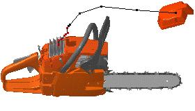
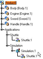
14 Page 14 Starting a Fitting Simulator Session Before starting this scenario, you should be familiar with the basic commands common to all workbenches. These are described in the DMU Navigator User's Guide. This first task will show you how to enter the Fitting Simulator workbench and select your products. 1. Select Digital Mockup -> DMU Fitting from the Start menu. The Fitting Simulator workbench is displayed. 2. Select File->Open. The File Selection dialog box displays: 3. Select the CHAINSAW.CATProduct from the samples folder. The samples are contained in C:/Program Files/Dassault Systemes/B08doc/online/fitug/samples folder. 4. Click Open to open the selected files. The specification tree is displayed showing all the selected products. In our example, the CHAINSAW.CATProduct has been divided in four main groups of objects. Note that you can also select model files using insert-> existing component. In this case, select the desired model files by clicking the first one then shift-clicking the last one you want.
15 Page 15 Use the Fit All In icon to position the model geometry on the screen. Clicking off View -> Specifications visible in the menu bar removes the specification tree and lets you use the entire screen for the product. You can also use the F3 key to toggle more quickly.
16 Page 16 Recording a Track Before starting this scenario, you should be familiar with the basic commands common to all workbenches. These are described in the DMU Navigator User's Guide. This task will show you how to record a track using products The CHAINSAW.CATProduct document is already open 1. Click the Track icon from the DMU Simulation toolbar The Track dialog box along with the DMU recorder and player are displayed: You can alter the name of the track by entering one in the Name field, or you can accept the default name provided. You can also set a speed for the movement or input a time by which the movement should be complete. 2. You are ready to record your track: select the product to move In our example, select DEMO_CGE_CHAINSAW_BODY_FILTERCOVER.1 either in the specification or in the geometry. The player becomes active and the Manipulation toolbar appears
17 Page Select the required interpolator. In our example keep the default one (Linear) Note: you can change the interpolator type at any time during your track recording 4. Move the 3D compass and click Record at each time position of your choice. If you double-click Record, the automatic insert mode is activated. Note: You can also use the Insert Key instead of clicking Record. You can modify or delete a position (referred to a shot) at any time, for this select the required shot in the geometry (use the Step Backward shot or Step Forward buttons in the Player to jump to a shot, make sure the Player unit is shot and the sampling step in the Player Parameters dialog box is set to 1), then perform the deletion (use the Delete key or the Delete icon ) or modification. The track is automatically updated. Alternatively, you can use the Reorder Shots command, which calls up the Reorder Shots dialog box. To move a shot up one place in the list, select the shot, and press the Up button. To move a shot down one place in the list, select the shot, and press the Down button. To insert a selected shot after next clicked shot, select the shot, click on the shot you wish it to follow and push the After button. Note: when editing a track, you can multi-select shots to be deleted (Select + CRTL key or Select +SHIFT key For more detailed information, please read Track Editor and Recorder and Player sections This is an example of what you can get:


18 Page 18 The track is created and identified in the specification tree (under Tracks item and within the product too) 4. Click OK to exit Track command. The modified position is kept

 edit the track (modify a position, delete a position.")
19 Page Click Reset to go back to the initial position. Note: you can at any time delete the track if you are not satisfied. 6. Right-click Track.1 and select track.1 item to access the track contextual menu and various operators. For detailed information, please read About Track Operators. For more detailed information about this menu items (referred to as track operators), see About Track Capabilities and About Track Operators. 7. Double-click Track.3 if you need to: replay your track simulation (use the dedicated Player) edit the track (modify a position, delete a position...) For instance play your track using the Play forward button: The time is specified in seconds in the Player (corresponds to the current time)

20 Page Check the speed and duration of your track simulation and modify it if necessary. All you need to do is right-clicking Track.1 in the specification tree and selecting Properties item from the contextual menu displayed. Then, enter a new speed value, the duration is recalculated. You can also modify the track name as desired. Click Ok when done. Note: the default speed is 0.001m_s (see: Customizing DMU Fitting) When you modify the speed and/or duration, the default value is automatically overwritten with the new speed value. About modifying the speed: For instance, you might need to reduce the track speed because your object is too heavy (keep in mind a track comprises of the track itself + the object), the duration is automatically recalculated (longer duration) and the speed is updated in Tools->Options-> DMU Fitting->Default speed.

21 Page 21 About customizing speed: If you modify the speed in the DMU Fitting tab, note that this modification will be taken into account for the new tracks to be created. For already created track use the Track Properties. For more detailed information, please refer to Customizing DMU Fitting
22 Page 22 At any time, you can: modify the loop mode, stop at a specific step or go back to the previous step (use step backwards and step forward and stop buttons) skip to the starting position or skip to the end (to the very last recorded position) Please also see: Player

23 Page 23 Using Automatic Path Finder Before starting this scenario, you should be familiar with the path finder command, please refer to Path finder chapter. This task will show you how to use the path finder capability on a track simulation. The CHAINSAW.CATProduct document is already open 1. Select the track created in the previous task (Track.1) either in the geometry area or in the specification tree. Note: you can also click the Path finder icon first and the object afterwards, in this case, the select dialog box lets you choose the objects 2. Click the Path finder icon from the DMU Check Toolbar. The Path Finder dialog box is displayed and lets you select options for: (The Basic mode is set by default)
 Off (You are not allowed to stop the process and you do not see the progression Strombo (shows positions based on")

24 Page 24 Visualization On (shows the object move and its various positions during calculation. You can stop the process at any time) Off (You are not allowed to stop the process and you do not see the progression Strombo (shows positions based on a specific parameter (every 20 steps) Steps Small Medium Large 3. Keep the default settings: Visualization: on Steps: Medium 4. Check the Ignore collisions checkbox to get rid of the irrelevant interferences. 5. Click Apply to confirm your operation. The progress bar is displayed letting you monitor and, if necessary, interrupt (Stop option) the calculation.


25 Page Click Ok. This is what you obtain: The path finder is a track operator. It is identified in the specification tree under a new track (Track.2), Track.1 is The option "ignore collisions" is identified under Parameters (knowledge parameters) Please see: Managing Operators' Options As Knowledge Parameters
26 Page 26 By default, the OK button does not perform the smooth, please select Tools->Options- >Digital Mockup->DMU fitting. Check the Automatic Smooth option. You are now ready to get rid of the unnecessary positions detected during path finder operation.


27 Page 27 Using The Smooth Command This task will show you how to smooth the automatic path finder defined in the previous task. 1. Click the Smooth icon from the DMU Check toolbar 2. Select the required track in the Select dialog box displayed. i.e: Track.4 The Smooth dialog box appears 3. Click Ok This is what you obtain:

28 Page 28 The smooth result ( track operator) is identified in the specification tree under Track.2 The parameters changed are identified too. Note: you can edit the parameters double-clicking them to display the Edit parameter dialog box. For example, if you double-click Translation step in the specification tree: Note: You can also display the track properties using the contextual menu.

29 Page 29 Updating a Track This task will show you how to update a track. We applied consecutively the following track operators: path finder and smooth, we need now to update the resulting track. 1. Right-click the track to be updated in the specification tree, i.e Track.4 2. Select the Track.4 object->update track items from the contextual menu displayed The path finder and the smooth computations are automatically launched The track is updated accordingly
30 Page 30
31 Page 31 Replaying a Track This task will show you how to replay a track using the dedicated Player 1. Double-click the track created (i.e. Track.1) in the specification tree or click the Track icon in the DMU Simulation toolbar 2. The player is displayed: 3. Click the Parameters icon 4. The Play Parameters dialog box appears: 5. Modify the time step and the temporization values if necessary. 6. Use the VCR buttons or the slider to simulate your track. skip to beginning step backwards play backwards stop play forwards step forwards
32 Page 32 skip to end For more information, please refer to Player

33 Page 33 Defining a Swept Volume Before starting this scenario, you should be familiar with the basic commands common to all workbenches. These are described in the DMU Navigator User's Guide. This first task will show you how to enter the Fitting Simulator workbench and select your products. 1. Select Track.1 in the specification tree and click the Swept volume icon. The Swept volume dialog box appears: 2. Click Preview. The computation is in progress The preview window appears:

34 Page Click Save in the Swept volume dialog box. The Save As dialog box is displayed 4. Select cgr file from the drop-down list

35 Page Enter a meaningful name and click Save. 6. Insert the SWEPTVOLUME_track.cgr into Product1, for this right-click Product1 and select Components->Existing Component from the contextual menu displayed. The Swept volume is identified in the specification tree and in the geometry area.
36 Page 36
37 Page 37 Using Shuttles Before getting into the detailed instructions for using DMU Fitting Simulator, the following tutorial aims at giving you a feel of what you can do with the product. It provides a step-bystep scenario showing you how to use key functions. The main tasks described in this section are: Starting a Session Exploding a Product Defining a Shuttle Recording a Simulation Replaying the Simulation These tasks should take about 15 minutes to complete.

38 Page 38 Starting a Fitting Simulator Session Before starting this scenario, you should be familiar with the basic commands common to all workbenches. These are described in the DMU Navigator User's Guide. This first task will show you how to enter the Fitting Simulator workbench and select your products. 1. Select Digital Mockup -> DMU Fitting from the Start menu. The Fitting Simulator workbench is displayed. 2. Select File->Open. The File Selection dialog box displays: 3. Select the CHAINSAW.CATProduct from the samples folder. 4. Click Open to open the selected files. The specification tree is displayed showing all the selected products. In our example, the CHAINSAW.CATProduct has been divided in four main groups of objects. Note that you can also select model files using insert-> existing component. In this case, select the desired model files by clicking the first one then shift-clicking the last one you want.

39 Page 39 Use the Fit All In icon to position the model geometry on the screen. Clicking off View -> Specifications visible in the menu bar removes the specification tree and lets you use the entire screen for the product. You can also use the F3 key to toggle more quickly.
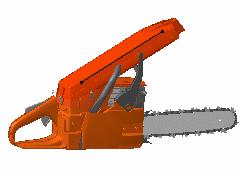
40 Page 40 Exploding a Product This task illustrates the use of the Explode capability. Exploding the view of an assembly means separating the components of this assembly to see their relationships. At any time though, you can check the product structure via the specification tree. The explode capability allows you to fully understand the product structure in a 3D context. CHAINSAW.CATProduct document is opened 1. Select Product1 in the specification tree. 2. Click the Explode icon. The Explode dialog box and the Manipulation toolbar are displayed Product 1 is the assembly to be exploded. The Depth parameter lets you choose between a total (All levels) or partial (First level) exploded view. 3. Set All levels if not already set. 4. Set 3D as explode type. You can now generate a sequence from the exploded view, all you need to do is click the Generate Sequence checkbox before launching the explode operation. For more detailed information refer to Generating a Sequence from an Exploded View
41 Page Click Apply to perform the operation. The Scroll Explode field gradually displays the progression of the operation. The application assigns directions and distances. Once complete, the assembly looks like this: The interest of this operation lies in the ability of viewing all components separately. You can easily move products within the exploded view using the 3D compass.
42 Page Click Apply to confirm the operation or click Cancel to restore the initial view.

43 Page 43 Defining the Shuttle Before starting this scenario, you should have loaded your CHAINSAW.CATProduct as described in the previous step. A shuttle is a set of products defined explicitly by selecting products individually. Shuttles are persistent and can be stored in the document. This task explains to you how to define the list of products you want to move together. 1. Select a product in the geometry area or in the specification tree. 2. Ctrl-click other products to add them to the initial selection 3. Select Insert->Shuttle... from the menu bar or click the Shuttle to create a shuttle: The Edit Shuttle dialog box and the Preview window appear. The 3D compass automatically positions according to the to-be-created shuttle axis. See below:

44 Page 44 You can define a maximum angle of rotation for the shuttle around the absolute axis you select. It means the shuttle motion is defined and validated with respect to the angle value defined. The Preview window shows selected products. 4. (Optional) Enter a meaningful name for the shuttle you want to create.

45 Page Click OK to create the shuttle. The shuttle is identified in the specification tree. Shuttles created in this manner are persistent and can be stored in the document. They are listed as separate entity in the specification tree and can be selected at any time and modified.

46 Page 46 Recording a Simulation Before starting this scenario, you should have created a "Shuttle" as described in the previous steps. This task explains how to quickly define the motion of a "Shuttle" and to record it in a simulation object. 1. Select Shuttle.1 in the specification tree. 2. Select Insert->Simulation... The 3D compass automatically positions according to the shuttle axis. The Edit Simulation dialog box and the Preview window appear. You are ready to record a simulation.
47 Page 47 You can now record a simulation with an animated viewpoint. For this, activate the Animate viewpoint option. For more details, please refer to Animating a Viewpoint. The first shot: shuttle in the origin position is already recorded in the simulation. 3. Select the manipulator to move the shuttle as desired. 4. Drag the cursor to the desired shuttle location.


48 Page Click Insert to save and insert in the "Simulation" the shuttle in the new position. 6. Insert another location in the same manner: You can select and drag all the components of the manipulator (axis, plane, arc, point) to move in different ways. 7. You can do several manipulations before inserting a new position in the "Simulation". 8. Click OK to end the Simulation creation. The simulation is identified in the specification tree.
49 Page 49

50 Page 50 Simulating a Replay Before starting this scenario, you should have created a "Simulation" with a shuttle at different locations as shown in the previous step. The CHAINSAW.CATProduct document is already opened. This task explains how to run a shuttle motion recorded in a "Simulation" using the Simulation command. 1. Double-click your "Simulation" in the specification tree (Simulation.1) The Edit Simulation dialog box and the Preview window appear.
51 Page 51 If you checked the Animate viewpoint option in the simulation recording, you can now animate viewpoints while recording a simulation. They are taken into account. For more details, please refer to Animating a Viewpoint. You also can select a "Simulation" graphically by clicking on the tracks. 2. Modify the interpolation value as desired. For example: Click the Play Forward button. The recorded motion is replayed.
52 Page 52 At any time, you can go back to the starting shot. Use the VCR buttons as desired: Play Forward (step by step) Go to Maximum Time position Pause Go to Zero Time position Backward (step by step) Play Back.
53 Page 53 Basic Tasks The table below lists the information you will find in the Basic User Tasks section. Setting Up Your DMU Fitting Simulator Session Shuttle Mono-Shuttle Fitting Simulation Target and Snap Capabilities Tracks Sequences Generating Animations Exploding
54 Page 54 Setting Up Your Fitting Simulator Session Enter the Workbench: select Digital Mockup -> DMU Fitting from the Start menu. An empty document opens. Define a Shuttle: 3 methods are available to create shuttles: Clicking the Shuttle icon first and select the objects afterwards. Selecting the objects first and activating the shuttle command after. Right-clicking Shuttle in the specification tree. The contextual menu is displayed.

55 Page 55 Entering the Fitting Simulator Workbench This task shows you how to enter the DMU Fitting workbench and open a new document. 1. Select Digital Mockup -> DMU Fitting from the Start menu. The Fitting Simulator workbench is loaded and an empty document opens: The Fitting Simulator workbench comprises: A Specification tree and a geometry area Specific Toolbars A number of contextual commands available both in the specification tree and the geometry area. 2. You are now ready to open models and products either using the Insert -> Existing Component... command or the Open->File... command. Clicking off View -> Specifications Visible in the menu bar removes the specification tree and lets you use the entire screen for the geometry. You can also use the F3 key. Note that more toolbars may appear next to the Standard toolbar when you create a document.
56 Page 56

57 Page 57 Defining a Shuttle A shuttle is a set of products defined explicitly by selecting products individually. Shuttles are persistent and can be stored in the document Open the TANK_WITHOUT_SHUTTLE.CATProduct document. This task explains how to define a shuttle. You will move this group of objects afterwards using a manipulator. For more details, please refer to Moving the Shuttle. 1. Select the required product in the geometry area as shown below: 2. Click the Shuttle icon. The Edit Shuttle dialog box and the Preview window appear:
58 Page 58 The manipulation toolbar is also displayed: The shuttle graphic representation is displayed. It corresponds to the to-be-created shuttle axis. You can specify a maximum rotation angle around the absolute axis for the shuttle. It can be very useful to avoid liquids to spill out from specific assemblies such as a gas tank for instance. It means the shuttle motion is defined and validated with respect to the angle value defined. 3. Check the Angle value option The value fields are no longer grayed out

59 Page Enter 45deg as angle value and select Y vector Note: Z vector is the horizontal axis therefore in our example we need to select Y vector which is the vertical axis to avoid spilling liquids The Preview window shows selected products. 5. (optional) Select products in the specification tree or in the geometry area to remove them from the shuttle. 6. (Optional) Enter a meaningful name for the shuttle you want to create.


60 Page Click OK to end the shuttle creation. The shuttle is identified in the specification tree and in the geometry area. Shuttles created in this manner are persistent and can be stored in the document. They are listed as a separate entity in the specification tree and can be selected at any time and modified. See Editing a Shuttle. If you need to deactivate the automatic display setting of the Preview window, uncheck the Manipulating objects option in the DMU Navigator tab via the Tools->Options command... For more details, please refer to Customizing DMU Navigator Settings in the DMU Navigator User's Guide.
61 Page 61 Shuttle About Shuttles: gives background information about shuttles Edit the Shuttle: in the specification tree, double-click the shuttle you defined to modify it or, right-click the shuttle and select Shuttle.1 object->definition from the contextual menu. Edit the fields required in the Edit shuttle dialog box and click Ok. More About Manipulation Toolbar: gives background information about manipulation tools Snap objects: Create a shuttle to be snapped onto an object and click the Snap icon. Customize Snapping settings if necessary (Tools->Options->DMU Fitting->DMU Manipulation. Record your simulation with automatic Insert option.

62 Page 62 About Shuttles A shuttle is a set of products defined explicitly by selecting products individually. Shuttles are persistent and can be stored in your document. Shuttles are identified by name in the specification tree and by a symbol in the geometry area. Shuttle creation: 4 methods are now available to create shuttles: Selecting Insert->Shuttle... Clicking the Shuttle icon first and select the objects afterwards. Selecting the objects first and activating the command after. Right-clicking Shuttle in the specification tree. The contextual menu displays the New Shuttle creation option. This is valid only if there is at least one shuttle defined Shuttles created in this manner are persistent and can be stored in the document. They are listed as separate entities in the specification tree and can be selected at any time and modified. About defining angular validation for shuttles: You can specify a maximum rotation angle around the absolute axis for the shuttle. It can be very useful to avoid liquids to spill from specific assemblies such as a gas tank for instance. It means the shuttle motion is defined and validated with respect to the angle value defined.
63 Page 63 You can define angular validation on products see definition above For this: Right-click the product in the specification tree Select Properties item from the contextual menu displayed Click Select the Validation tab Check the Angle option. Now, enter the appropriate value and select the vector of your choice Click Ok to confirm your operation

64 Page 64 What are you moving? By default, the Shuttle option is set, which means that when you move a shuttle the axis and geometry move together. If you choose to set the Axis option instead, only the shuttle axis moves. Please refer to Moving the Shuttle
65 Page 65 Shuttle axis behavior: You created a shuttle clicking the icon first ( action->object) the shuttle is empty, the shuttle axis is at the absolute origin (document). you add an object to this shuttle, by default the shuttle axis moves to the bounding box center of this object. You created a shuttle selecting objects first (either in the geometry area or in the specification tree) (object->action) the shuttle comprises one or more objects, the shuttle axis is positioned at the bounding box center of the objects selected. you add an object to this shuttle, the shuttle axis does not move. Snapping Shuttle on Geometry: Use the Ctrl key and the 3D compass manipulation handle to drag the shuttle onto the required object. Then, release the mouse button to drop both the shuttle and compass onto the object. You can use at any time the Manipulation toolbar. For more details, please refer to Manipulation Toolbar. and More about Manipulation toolbar.
66 Page 66 More About Manipulation Toolbar Shuttle-based manipulation toolbar Track-based manipulation toolbar DMU Fitting Simulator lets you validate the dismounting of assemblies by moving objects and generating simulations. Therefore, this capacity to manipulate 3D objects with a 2D mouse comes to the fore. Thus, DMU Fitting Simulator provides powerful tools available from the manipulation toolbar displayed every time you are working in edit shuttle mode, Explode, Track and Simulation commands (if based on one or various shuttle(s).) Let's detail it more carefully Preview: click this icon to view the selected and manipulated objects in a dedicated window Reframe: Fits manipulated objects into the space available in the preview window Target: In some cases, you need to reposition the shuttle on the geometry (namely on the symmetry axis, on rotation centers...). When you do not work in design mode, you do not have the original geometry. various options are available use Target in one shot use Target in two shots use CRTL key + 3D Compass Please refer to Moving the Shuttle, Using Target Capability, and About Shuttles Editor: lets you edit 3D Compass position (displays the Compass manipulation dialog box) See Moving the Shuttle Invert: inverts the 3D compass orientation and the shuttle attached Reset: swaps to the initial shuttle position
67 Page 67 Snap: lets you define the snapping axis, to snap the shuttle onto an object in approach phase (in simulation) Please refer to Snapping objects and Customizing DMU Manipulators Attach/Detach: lets you move the 3D compass independently from the shuttle.


68 Page 68 Editing a Shuttle A shuttle is a set of products defined explicitly by selecting products individually. Shuttles are persistent and can be stored in the document. This task shows how to edit a shuttle. This procedure can be performed either before the shuttle creation or after. Open the CHAINSAW.CATProduct document, then select Digital Mockup -> DMU Fitting from the Start menu. You defined at least one shuttle. For more details please refer to Defining a Shuttle. 1. In the specification tree, double-click the shuttle you defined to modify it or, right-click the shuttle and select Shuttle.1 object->definition from the contextual menu. The Edit Shuttle dialog box appears and displays the contents of the shuttle you selected. Objects included in the shuttle are highlighted in the specification tree and in the geometry area. 2. Modify shuttle contents as desired. For this: 3. (optional) Select objects in the specification tree or in the geometry area to remove them or select new ones to be added. 4. (optional) Rename the shuttle. For instance, enter Shuttle.1a in the Name field.

69 Page 69 Your operation is automatically taken into account. The selection field from the Edit dialog box is automatically updated as well as the Preview window. The new selection is highlighted in the specification tree and in the geometry area. 5. Click OK to confirm your operation. By default, the Shuttle option is set, which means that when you move a shuttle the axis and geometry move together. If you choose to set the Axis option instead, only the shuttle axis moves. Please refer to Moving the Shuttle You can use at any time the Manipulation toolbar. For more details, please refer to Manipulation Toolbar.

70 Page 70 Snapping Objects in Approach Phase This scenario aims at showing you how a snapping position can be useful in a mounting operation. We are going to focus here on the nuts. The nut initial position is interesting and useful this is why we are going to create a shuttle on this object This task shows how to reposition with precision objects on the geometry using the snap capability. Open the SNAPPING.CATProduct document. 1. Use the View->Zoom In command and drag (left mouse button) to zoom in progressively until you are satisfied. 2. Select Nut 1 either in the geometry area or in the specification tree. 3. Click the Shuttle icon from the DMU Simulation toolbar. 4. Make sure you work with the privileged plane VW. Point to the compass and right-click to display the contextual menu. Select the command Make VW the Privileged Plane.


71 Page Click the Snap icon from the Manipulation toolbar. A red axis system appears on the shuttle. The current shuttle axis position is recorded. 6. Click Ok to end the shuttle creation. Now you might need to customize the snapping settings 7. Use Tools->Options->DMU Fitting->DMU Manipulation to customize snapping settings Set values for the: Position: 6mm (keep the default value) Orientation: 200mm (20mm is the default value)


72 Page Click Ok to take your modifications into account 9. Drag and drop the Simulation icon on shuttle.1 in the specification tree, please refer to Dragging and Dropping Icons Onto Objects in the Infrastructure User's Guide 10. Move the shuttle as shown below: 11. Set the Automatic insert option in the Edit Simulation dialog box. 12. Start recording your simulation moving the shuttle towards the disk.


73 Page 73 The nut is snapped as shown below Use the smooth command to get rid of the unnecessary positions.
74 Page 74 Mono-Shuttle Fitting Simulation Record a Simulation: click the Simulation icon or select Insert->Simulation... from the menu bar. Move the shuttle as often as necessary, clicking Insert to record shots then press OK to confirm your operation. Record a Simulation Automatically: click the Simulation icon or select Insert- >Simulation... from the menu bar then set the auto insert option in the Edit Simulation dialog box. Click the Auto Insert icon from the Manipulation toolbar and choose the required settings. When done click OK and start recording your simulation. Using the Smooth Command: select the simulation in the specification tree and click the smooth icon. Click Ok. Animate a Viewpoint: replay your simulation now with the Animate viewpoint option set. The simulation is replayed with the viewpoint changes recorded in the simulation. Generate a Replay: select Tools->Simulation->Generate Replay Select the track or the simulation you want to generate a replay from. Click OK to create a replay object. Generate an Animation File: provides information on how to generate an AVI file with the standard tools Replay a Simulation: Select Tools->Simulation->Replay or double-click the Replay in the specification tree. Replay the recorded simulation using the VCR buttons.

75 Recording a Simulation Page 75 This task shows how to record a Simulation, in other words a scenario on mono-shuttle fitting simulation. Open the RECORD_SIMULATION.CATProduct document. 1. Select Insert->Simulation... from the menu bar. The Select dialog box is displayed and lets you select the shuttle you want to use in your Simulation. The Edit Simulation dialog box and Preview window appear. Note that you can also choose to select the shuttle first, and the simulation icon afterwards. In this case, the select dialog box is not displayed. 2. Click the Insert switch and record the starting shot. Note that you can change the automatic display setting of the Preview window via the Tools->Options command... Insert means that you record and insert shots inside the scenario. The initial location of the shuttle is automatically recorded as a starting shot. If you need to reposition the shuttle, please delete the first position or modify it.

76 Page 76 For more detailed information about the sensors, please refer to DMU Kinematics Simulator User's Guide, Using Sensors 3. Move the shuttle to the desired location via the manipulator. 4. Click the Insert switch and record the desired shot. 5. Move the shuttle as often as necessary, clicking Insert to record shots. You can activate the automatic insert at any time. For more detailed information, please refer to Recording a Simulation Automatically 6. Select the appropriate interpolation, for instance You can modify or choose the automatic insert at any time. 7. Click OK to confirm your operation. The Simulation is identified in the specification tree.

77 Page 77 At any time, you can press the Edit Analysis button from the Edit Simulation dialog box: It is empty because you have not defined interferences. The Edit Simulation objects button lets you add simulation objects such as cameras... You recorded a simulation based on shuttles. Here, you selected the shuttle.2. Keep in mind that editing shuttles impacts the simulation.
78 Page 78 Recording a Simulation Automatically This task shows you how to record a Simulation automatically using the automatic insert functionality, the automatic clash detection in Mouse moving mode ( possibility to record distance and angle steps) You can manipulate the shuttle with the mouse or the space ball/space mouse Open the TANK_SHUTTLE.CATProduct document. Make sure the settings are correct: For more information, please see Customizing DMU Manipulators 1. Select Tools->Options... from the menu bar The Options dialog box appears. Click the DMU Fitting item Click the DMU Manipulation tab 2. In the Automatic Insert Configuration field, check the "While mouse moving" option 3. In the Manipulation Mode for Shuttle simulation, check the "Stop on collision" mode as well as the "Automatic insert" option


79 Page Click Ok to confirm your operation. Your new settings are taken into account. 5. Double-click the Shuttle.1 (defined on the tank) in the specification tree: the angle option is set to 45 deg close the edit shuttle dialog box The shuttle motion is defined with respect to the rotation angle defined 6. Select Shuttle.1 in the specification tree. 7. Select Insert->Simulation
 8. Start recording your simulation using the mouse left-button. 9.")

80 Page 80 The Automatic insert option is checked in the simulation dialog box and the Stop on collision mode is activated ( ) 8. Start recording your simulation using the mouse left-button. 9. Move the shuttle as often as necessary, the shots are recorded automatically 10. The simulation stops when the shuttle is in collision, the product is highlighted. This position is not recorded, the stop on collision lets you validate the simulation. This is what you obtain:

81 Page Click Ok in the Edit Simulation dialog box. The recording precision depends on the manipulation speed. It means the precision is approximate as the recording limit is based on the upper distance selected.


82 Using the Smooth Command Page 82 This task shows how to smooth positions in a simulation. You recorded a simulation using the space ball and automatic insert capability. You used the automatic clash detection. The smooth command lets you obtain a path without collisions as it removes the useless positions. Open the SMOOTH.CATProduct document. 1. In the specification tree, select Simulation Click the Smooth icon. The Smooth dialog box is displayed Enter 10 mm in the Translation step field.


83 Page Click OK. This is what you obtain: 4. Now close your SMOOTH.CATProduct without saving the modifications. Open the SMOOTH_TRACK.CATProduct document (a track is defined) 5. Select Track.1 either in the specification tree or in the geometry area


84 Page Click the Smooth icon. The Smooth dialog box appears. Keep the parameters values and click Ok
, shot parameter or, path finder or smooth specifications if previously defined (this is the case in our example)")
85 Page 85 The track is smoothed Now you are going to play your smoothed track: 7. Click the Play a Simulation icon and select Track.1 in the specification tree The Player is active. New parameters are available to replay your track with respect to: time (in seconds), shot parameter or, path finder or smooth specifications if previously defined (this is the case in our example) To avoid interpolation consistency problems, (fixed by the auto controlled step option in the previous releases), you can now replay your smoothed track using the pathfinder parameter in the player drop-down list: selecting pathfinder parameter in the drop-down list swaps to the right interpolation (spatial-based interpolation, smooth specification) 8. Of course, you can choose to keep the default parameter (time in seconds), but it this case the consistency between the smooth specification and the way it is played are not guaranteed Click to play your smoothed track.
86 Page 86

87 Page 87 Animating a Viewpoint in a Simulation This task shows how to animate viewpoints in a simulation. Open the RECORD_SIMULATION.CATProduct document. 1. Select the shuttle.2 either in the geometry area or in the specification tree. 2. Click the Simulation icon. The Edit Simulation dialog box and Preview window appear. 3. Click the Insert switch and record the shots. Remember the initial position is automatically recorded. If you need to reposition the shuttle, please delete the first position or modify it. Insert means that you record and insert positions with the current viewpoints inside the scenario.


88 Page Move the shuttle to the desired location via the manipulator. 5. Click the Insert switch and record the desired position. 6. Move the shuttle as often as necessary, clicking Insert switch to record shots. Change the viewpoint as shown below:

89 Page Select the appropriate interpolation. You can modify or choose the automatic insert at any time. The Simulation is identified in the specification tree Automatic Insert: You can activate the automatic insert at any time. For more detailed information, please refer to Recording a Simulation Automatically 8. Replay your simulation now with the Animate viewpoint option set. The simulation is replayed with the viewpoint changes. Note that you can activate the Animate viewpoint option at anytime either before recording the simulation or after. 9. Click OK to save your simulation. You are now ready to create a replay or an animation. This is done by compiling your simulation. You recorded a simulation based on shuttles. Here, you selected the shuttle.2. Keep in mind that editing shuttles impacts the simulation.

 Enter a meaningful name for the replay you want to create. 3.")
90 Page 90 Generating a Replay This task shows how to generate a replay object a recorded Simulation to generate a replay or an animation You recorded a Simulation. Please refer to Recording a Simulation Open the COMPILE_SIMULATION.CATProduct document. 1. Select Simulation.1 in the specification tree. 2. Select Tools->Simulation->Generate Replay. The Replay Generation dialog box is displayed. (Optional) Enter a meaningful name for the replay you want to create. 3. Click Ok to confirm your operation The Replay object is identified in the specification tree
91 Page 91

92 Page 92 Replaying This task shows how to rerun the Replay object resulting from the Compile Simulation. Open the REPLAY_SIMULATION.CATProduct document. 1. Select Tools->Simulation->Replay or double-click the Replay.2 in the specification tree. The Replay dialog box is displayed: 2. Specify the desired speed: x 1 for instance. Check the Animate viewpoint option if you want to take into account the viewpoints recorded during the simulation. Of course assigning a high number of interpolations amounts to replaying the scenario at a very low speed. 3. Go back to the starting shot. For instance, use the VCR buttons.


93 Page Step forward. 5. Modify the speed at any time. 6. Step forward again 7. Replay the scenario back to the starting shot and at a 1 interpolation number between recorded shots. You can choose one of the loop modes to re-run the animation in a continuous way (either in one direction only or in one direction then the other).
94 Page 94 Target and Snap Capabilities About the Target Capability: Use the Ctrl key and 3D compass to drag the shuttle onto the required object. Use Smart Target: Double-click the target icon, select the first object to be moved, select the geometry and release the mouse button, repeat the operation with a second object a constraint is created. Select as many objects as necessary Use Smart Snap: Double-click the snap icon, select the geometries you need to detect, click Ok, record your track. The geometries are snapped interactively Move the Shuttle: double-click the shuttle in the specification tree. The 3D compass lets you move the shuttle as desired.
95 Page 95 About Target Capability About Snapping objects (shuttle, products in track) on Geometry using the Smart target While creating or editing a track, a simulation or a shuttle, it is welcome to be able to catch an entity very precisely. The smart target command lets you do this. Beside, it can be useful to cumulate several targets. Indeed, using a historical target can help to put some elements in a specific position. In some cases, you need to reposition objects on the geometry (namely on the symmetry axis..) For example you need to reposition the screw in the hole. If you do not work in design mode, which means you do not have the original geometry, three options are available to reposition the object (shuttle or product in track) 1. Use the Target icon from the manipulation toolbar in one shot. Double-click the shuttle or the track in the specification tree or in the geometry area. The manipulation toolbar is displayed. Click the target icon. The object to be moved (shuttle, product, camera included in a shuttle or a track ) is selected Point the cursor on the geometry (belonging to the to- be- moved object) Click the mouse button Select a second geometric element (belonging to the receiving object) Click the mouse button to validate your selection A coincidence constraint is created, the object is snapped to the desired location. 2. Use the Target icon from the manipulation toolbar in several shots Double-click the shuttle or the track in the specification tree or in the geometry area. The manipulation toolbar is displayed. Click the target icon to activate the smart target The first object to be moved is selected (object attached to the shuttle, product or camera included in a shuttle or a track ) Select a first geometric element (on the to-be-moved element)
96 Page 96 Click the mouse button Select a second geometric element (on the receiving element) Click the mouse button Select a third geometric element (on the to-be-moved element) Click the mouse button Select a fourth geometric element (on the receiving element) Two coincidence constraints are created. 3. Use CTRL key and the 3D Compass Now when you work in design mode (the original geometry is available) The Target capability recognizes the geometric features (edges and faces) The easiest way to snap the shuttle on geometry is to use CTRL key and the 3D Compass For more information about Target, please refer to Using Smart Target. This task shows how to reposition with precision the shuttle on the geometry using CTRL key and the 3D Compass in design mode. You defined a shuttle. Please refer to Defining a Shuttle Open the plane.catproduct document. 1. Select Edit->Representations->Design Mode... to snap the shuttle on geometry (axis, points, intersection points) 2. Double-click the shuttle in the specification tree (shuttle.1). The Edit Shuttle dialog box, the Preview window and the Manipulation Toolbar appear. 3. Move the shuttle (shuttle.1) as shown below
 you are")


97 Page 97 Now you need to snap the shuttle on geometry (in this case to the wheel axis) you are going to reposition the shuttle in its initial position. 4. Use the Ctrl key and 3D compass manipulation handle to drag the shuttle onto the required object. 5. Release the mouse button to drop both the shuttle and compass onto the object. The shuttle is snapped on geometry. 6. Reposition the shuttle if needed.
98 Page 98 About Smart Target: Using Smart Target The Smart target command consists in creating a series of constraints on-the-fly, thereby reducing the degrees of freedom of the components While creating or editing a track, a simulation or a shuttle, it is welcome to be able to catch an entity very precisely. It can be useful to cumulate several targets. Using a historical target (keeping track of cumulative constraints) can help to put some elements in a specific position. For instance, the scenario below aims at showing you the interest of this new capability: you want to move P2 in P1, using the smart target, we can create a first coincidence constraint between the two planes referred to as PL2 and PL1 then, we add a second coincidence constraint between the two axis AX2.1 and AX1.1 finally we add a third coincidence constraint between the two axis AX2.2 and AX1.2 What is the advantage? Using the previous target functionality would have resulted in: only P2 translation by the third coincidence constraint the coincidence constraint 2 being lost

99 Page 99 This task show you to use the Smart Target in a track recording scenario. Open the SMART_TARGET.CATProduct document Select Disk.1 either in the specification tree or in the geometry area Click the Track icon from the DMU Simulation toolbar. You are ready to record your track: select the product to move In our example, select Disk.1 either in the specification or in the geometry. The player becomes active and the Manipulation toolbar appears 3. Click the Target icon from the Manipulation toolbar to activate the smart target The Disk is selected and thus highlighted in the geometry area


100 Page Select a geometric element (a point, line, plane or axis system) on the same to-be-moved component, e.g. a circle of which the center is the center of the entire Disk cylinder in the sample product. 5. Double-click Insert in the Recorder to activate the automatic insert mode. Please refer to Track Editor and Recorder and Recording a Track 6. Select the Rim cylinder axis as shown below The first coincidence constraint is created. The Disk cylinder is displaced in accordance with the first constraint. You can continue directly to the creation of the second constraint.


101 Page Now click the Invert button to position the Disk: The disk is automatically inverted 8. Select a geometric element on the to-be-moved component, e.g. the axe passing through one of the nuts of the Disk cylinder. (left picture) 9. Select a geometric element on the receiving component, e.g. the axe passing through one of the nut holes of the Rim cylinder. (right picture)


102 Page 102 The second constraint is created. The Disk cylinder is displaced in accordance with the second constraint. You can continue directly to the creation of the third constraint. 10. Select the plane of the Disk cylinder containing the nuts. 11. Select the plane of the Rim cylinder containing the nut holes. The third constraint is created. The two components have been placed together as a function of the three constraints. This is what you obtain The third constraint is created. The two components have been placed together as a function of the three constraints.


103 Page 103 The track is created, you can replay it Click the Target icon to exit the command
104 Page 104 What about the geometric features recognized when using the Smart Target capability? Geometric Features Design mode Visualization mode cylinder axis Y Y surfaces Y Y Y Y edge : extremities Y Y Any point (CTRL key) camera (eye) Y Y V4 axis system Y Y construction lines construction axis Y Y The table below describes the smart target behavior and its advantages with respect to the previous one Selectable elements Previous Target Smart Target Any point (using the Mouse + CTRL key) Yes Yes Line Yes Yes V4 Axis System Yes Yes
105 Page 105 Plane Yes Yes Shuttle Axis (using the Mouse + SHIFT key) Yes Yes Selection order 1. Object to be moved is already selected 2. first geometrical element 3. second geometrical element shuttle or product in track could belong to the active element, or to the global environment in order to snap the compass base plane on the same or on a different component shuttle or product in track must belong to the object to be moved (the active element) on a different object Design/visualization modes Yes except for V4 axis systems, construction axis and construction lines Yes Repetitive Mode No Yes Two constraints can be opposite and thus become a limitation for the use of smart target.
106 Page 106 About Smart Snap: Using Smart Snap The Smart snap command consists in creating a series of constraints on-the-fly, thereby reducing the degrees of freedom of the components While creating or editing a track, a simulation or a shuttle, it is welcome to be able to position an entity very precisely. It can be useful to cumulate several targets. Using a historical target (keeping track of cumulative constraints) can help to put some elements in a specific position. For instance, the scenario below aims at showing you the interest of this new capability: You are creating a track attached to Part2, you need this part to be plugged into Part1 Click the smart snap icon in the manipulation toolbar Select the geometries you want to focus on: L1, L2, L3 and L4 (the selection order does not matter) Click Ok in the dialog box displayed You can manipulate easily Part2 and creating the track, each time a geometry or several geometries of Part2 approaches another geometry (or several other geometries) of the environment, the magnet effect acts, snapping the geometries (in our example L1 with L3, or L2 with L3 or L1 with L4 and L2 with L3...) What is the advantage? The smart snap can be used interactively

107 Page 107 This task show you to use the Smart snap in a track recording scenario. The objective is to snap the CHAINSAW_ENGINE_FLYWHEEL to the CHAINSAW_ENGINE_CRANKSHAFT_LSIDE.1 Open the SMART_SNAP.CATProduct document. 1. Select Tools->Options->DMU Fitting->DMU Manipulation to customize snapping settings Set values for the: Position: 6mm (keep the default value) Orientation: 20mm (keep the default value) 2. Select the object to move either in the specification tree or in the geometry area In our example: select shuttle.1

 For instance, first select the axis (cylinder) on the CHAINSAW_ENGINE_CRANKSHAFT_LSIDE product and")
108 Page Click the Track icon from the DMU Simulation toolbar. You are ready to record your track The player becomes active and the Manipulation toolbar appears Click the Target icon in the Manipulation toolbar to activate the smart snap Select the geometries you need to detect : You want to snap the CHAINSAW_ENGINE_FLYWHEEL1 product to the CHAINSAW_ENGINE_CRANKSHAFT_LSIDE product 6. Select the appropriate geometries (the selection order is not relevant) For instance, first select the axis (cylinder) on the CHAINSAW_ENGINE_CRANKSHAFT_LSIDE product and click to confirm the operation Then, select a plane (inner one) on the CHAINSAW_ENGINE_FLYWHEEL1 product and click


109 Page 109 Back to the CHAINSAW_ENGINE_CRANKSHAFT_LSIDE product, select the inner plane as shown below and click To finish, you need to select another axis on the CHAINSAW_ENGINE_FLYWHEEL1


110 Page Click Ok in the dialog box displayed 8. Double-click Record in the Recorder to activate the automatic insert mode. Please refer to Track Editor and Recorder and Recording a Track Move the shuttle so as to approach it towards the object

111 Page 111 The planes are snapped together as well as the axes. The track is created, you can replay it using the player 9. Click the Target icon to exit the command 10. Click Ok in the Track dialog box What about the geometric features recognized when using the Smart Target capability? Visualization Selectable elements Design Mode mode Point Yes Yes Line Yes Yes V4 Axis System Yes Yes Plane Yes Yes
112 Moving the Shuttle Page 112 This task shows how to move the shuttle you just defined to the desired location. For this, you will use the graphic manipulator referred to as the 3D compass. Note that, by default, the graphic manipulator is attached to the shuttle. See the Manipulation toolbar the Attach icon is activated. You defined a shuttle. Open the MOVE_SHUTTLE.CATProduct document. 1. Double-click the shuttle in the specification tree (shuttle.1) The Edit Shuttle dialog box, the Preview window and the Manipulation Toolbar appear. 2. The 3D compass snaps to the shuttle axis.


113 Page 113 The Move shuttle option is activated by default which means that both the shuttle axis and geometry move together. 3. Click the z axis from the manipulator. 4. Drag the cursor to the shuttle desired location. 5. Click the x plane from the 3D compass. 6. Drag the cursor to the left. 7. Use the Reset command when needed. 8. Select the z axis and drag the 3D compass.


114 Page Drag the cursor to the shuttle desired location. 10. Now rotate the shuttle. For this: drag an arc of the compass, for example dragging the arc x z to the left rotates the shuttle in the plane subtended by the arc x z like this: 11. Click the Reset icon. Now, you are going to use the target icon 12. Move the shuttle.1 as shown below

 Click the mouse button.")

115 Page 115 Now you want to reposition the shuttle (startinghouse) as it was/ 13. Click the Target icon. The shuttle is selected and highlighted in the geometry area Point the cursor on the first geometric element (a cylinder axis) Click the mouse button. Select geometric element on the receiving component The first coincidence constraint is created. The shuttle is displaced in accordance with the first constraint. You can continue directly to the creation of the second constraint.


 The second coincidence constraint is created.")
116 Page Select a geometric element on the shuttle (point the cursor) e.g. the left hole axis as shown below Click the mouse button. Select geometric element on the receiving component, a hole axis (right picture) The second coincidence constraint is created. The shuttle is displaced in accordance with the second constraint. You can continue directly to the creation of the third constraint.


117 Page Select a geometric element on the shuttle e.g. a line on the shuttle as shown below Click the mouse button. Select geometric element on the receiving component, a line (right picture) The third coincidence constraint is created. The shuttle is displaced in accordance with the third constraint.


118 Page Click the Target icon to exit the Smart target command. You may also enter more precise coordinates using the Compass Manipulation dialog box. For this you can either: right-click the 3D compass and select edit from the displayed contextual menu or click the Editor icon from the Manipulation toolbar.

119 Page Click OK in the Edit Shuttle dialog box.
120 Page 120 Tracks About track capabilities: provides detailed information about track capabilities (track entity is considered in its overall) Track editor and recorder: provides information about the DMU Fitting dedicated tools. DMU player: provides detailed information about the player. Copy and paste tracks: right-click the track to be copied. Select Copy from the contextual menu, then rightclick tracks item in the specification tree and select Paste from the contextual menu. Double-click the pasted track to change the object selection. About track operators: provides detailed information on how to use operators Analyze in track context: select a track, click add clash on track button in the Track dialog box, then select analyses in the Analysis list and click Bound Export and import tracks in neutral format: select the track and then Tools->Simulation->Track File Export or Tools->Simulation->Track File Import. Enter a meaningful name and select.xml format from the Save as Type drop-down list: Edit Time Line in Tracks: select the track to be edited, click more and either drag and drop the segment or enter a precise value in the shot time field. Please also read About Target Capability
121 Page 121 About Track Capabilities A track is a route of a moving object Objects can be: products shuttles section planes lights cameras: It is possible to have an active camera automatically updated from the current view, exactly as if you'd selected Update from View each time you change the view using any combination of translates, rotations and zooms. (A camera is considered "active" when it is selected or edited in a track.) Please refer to Using Camera Capabilities and Recording a Camera Track inverse Kinematics (IK) points from Human Builder manikin constrained.catpart attached to a manikin (the part is moved as well as the manikin with respect to his IK) Note: Those capabilities are available if you have a Human Builder license.
 You can insert, modify, delete a position with a dedicated tool (see: Track Editor and Recorder and Recording a Track) This is a time-based trajectory.")
122 Page 122 Tracks are persistent and can be stored in your document. Tracks comprise defined positions associated with time parameter. The current time is materialized with a green bullet. About track properties (speed/duration) You can insert, modify, delete a position with a dedicated tool (see: Track Editor and Recorder and Recording a Track) This is a time-based trajectory. This trajectory can be interpolated with different interpolation types:
123 Page 123 linear ( default type for product, shuttles, section planes and lights) spline (default for cameras and lights) composite spline (enables to minimize the impact of position modifications on the entire trajectory) The lets you access and edit the duration for each segment (between two positions) you can : edit segment duration within the Track dialog box using the More button modify quickly the segment duration using drag and drop capability enter a precise value to modify this duration. Useful keyboard shortcut: Select + CTRL key: lets you drag each and every segment of the time line representation without changing the global duration. Please read: Editing Time Line in Tracks
124 Page 124 The button lets you access the edit object dialog box (if the object is a shuttle, a section plane, a light or a camera (when the moving object is a camera, a light or a section plane: clicking the Edit button display the Properties dialog box) Note: the Edit button is grayed out if the moving object is a product. Positions in the track are defined with respect to the moving object coordinates. (i.e. let's say a track is defined for a light bulb, if the light bulb position is modified in the product definition, the track is updated accordingly and therefore remains consistent) A track can be modified through a various number of operations referred to as track operators Reverse time Join tracks Split track Mirror track Transform Path finder Smooth Swept volume The following can be accessed through the track contextual menu: Reverse time Join tracks Split track Mirror track
125 Page 125 Others can be accessed using standard commands: Transform (rotation/translation using 3D compass) Path finder (DMU Check toolbar) Smooth (DMU Check toolbar) Swept volume (DMU Simulation toolbar) The various track operators are logged using a history displayed in the specification tree. The initial track is considered as a specification, track operators are applied to this initial track. The new track defined is the final result (this is displayed in the specification tree and in the geometry area). The original tracks are hidden, in other words visible in no show space but displayed in the specification tree. This "history" can be deleted at any time but note that keeping this history gives you the possibility to update the resulting track as you wish when the original specifications change. Simulation You can simulate your track using the dedicated player (see DMU Player) You can therefore generate an animation file ( AVI format) with DMU standard tools. (select Tools->Image->Video...) You can compile your track to generate a replay object (using Tools->Simulation- >Generate Replay...) You can validate your track using the default clash available from the Automatic Clash detection toolbar as well as check interferences and calculate distances specifications. (See: Validating a Motion and Analyzing in Track Context
126 Page 126 Leaving product in modified position When you exit the track command, the product remains in its modified position. it can be useful to: use it as starting position for a new simulation (i.e. you need to open the front hood before dismounting the spark plugs) save this position as a new product configuration If you need to go back to the initial product position, either play the simulation from the starting position (but it is not very handy when you created several tracks) or use the Reset command from the DMU Simulation toolbar. Changing the moving object You can change the moving object at any time using the track editor (simply click the object selection field) The track can be relocated on this new object or not. Please refer to Track Editor and Recorder Example.1 (keep current track position option) A track is defined to dismount various objects through a bottleneck. The track needs to remain at the same location with respect to the bottleneck whatever the object is, in this case, you should keep current track position. Example.2 (relocate track on new object option) A track is defined to unscrew a spark plug. You want to make sure this track can be applied to another spark plug. In this case, changing the moving object along the track is valid only if you can unscrew the second spark plug from its current location, use the automatic relocate track (Do not keep positioning option).
127 Page 127 Copy/Paste capability You can copy and paste tracks to create instances of reference tracks. If you modify the "shot positions" of a track, the reference track is therefore modified and all the instances will be modified (either instance or reference tracks). Then, you can apply track operators (see About Track operators) on instances, for instance to relocate them keeping the links existing between the references and instances) i.e. You defined a track to remove a spark plug. You create instances for the other spark plugs, you can modify the moving object along the track to move the other spark plugs with respect to the current position of the spark plug instance. All the spark plug instances will be moved with the same motion. See: Copying and Pasting Tracks Break link This capability lets you break the link existing between the reference track and its instances. i.e. in the above example, one of the spark plug cannot be dismounted in the same manner, you can use break link to modify this particular instance track without impacting the others. Clash reporting You can through the publish capability, obtain a concise clash.html report on a single track simulation (automatic clash detection + regular clash analysis) Scenario 1. Interferences specifications are defined and linked to tracks in your document. 2. Activate the publish functionality (select Tools->Publish->Start publish...) please read Publishing in the DMU Navigator User's Guide, and also read Publishing 3. Click the Player icon. 4. Activate the automatic clash detection 5. Click Play forwards button in the Player toolbar The clash detection is launched
128 Page Click Stop publish icon or select Tools -> Publish -> Stop Publish. 7. Read your published clash report For more detailed information, please refer to Analyzing in Track Context About Journaling/automation Tracks are journalized. You can generate a macro using Tools->Macro->Record... (see the Infrastructure user's Guide) Track creation: 2 methods are now available to create tracks: Clicking the Track icon first and select the objects afterwards. Selecting the objects first and activating the command after. Tracks created in this manner are persistent and can be stored in the document. They are listed as separate entities in the specification tree and can be selected at any time and modified.
129 Track Editor and Recorder Page 129 Information follows about the track capability display, including the player toolbar, the DMU recorder toolbar, and the track editor function. About the Player Toolbar More detailed information is provided (about Player shortcuts for instance) in the Player task. Use the VCR buttons or the slider to simulate the movement of parts along your track. Skip to beginning Step backwards Slider: As you move the slider, you make the simulation move forwards or backwards. Selecting Time makes the simulation proceed according to the simulation time. The time units (by default, seconds) are set in Tools->Options- >Parameters and Measure->Units. Selecting Shot makes the simulation jump from one shot to another, in sequence. Play backwards Stop Player parameters button. More information appears below. Loop Mode Single loop (shows simulation once, from beginning to end). Play forwards Step forwards Note: This is the default value. To see other loop options, click on this button. The option that is visible is the one that will be operating. Continuous loop, from beginning to end, then jumps back to beginning. Skip to end Continuous loop, from beginning to end, then end to beginning. Selecting the player parameter button brings up a dialog box that enables you to set a sampling size so that you see the simulation at steps of every 1, 2, or 5 seconds. You can also select an temporization option, which enables you to determine how quickly you see the simulation. Without selecting the parameters, you see one second of the simulation in one second of real time. If you want to view the simulation more quickly, you can set the temporization size smaller (e.g., to.25 s) and the sample size larger (e.g., 5 s). About the Recorder Toolbar
. To deactivate this mode: Click once.")
130 Page 130 One click: Records shots one after another. Double-click: Activates the auto insert mode (see Automatic Insert configuration using Tools->Options- >Digital Mockup->DMU Fitting->DMU Manipulation). To deactivate this mode: Click once. One click: Records modification(s) on one shot at a time. Double-click: Records modification(s) in continuous mode. You need to be positioned on the required shot. On the Player toolbar, use the Steps Backwards and/or Steps Forwards icons to position the manipulator on the required shot. To deactivate this mode: Click once. Deletes one shot after another. The cursor must be position on the shot to be deleted. Note: In track edition context, if you need to delete various shots at a time, multi-select them (Select +SHIFT key or Select +CTRL key) and use the Delete Key or the Delete item from the contextual menu. Reorders shots. To use: 1. Select a track. 2. Click on the Reorder button. The Reorder dialog box appears: To move a shot up one place in the list, select the shot, and press the Up button. To move a shot down one place in the list, select the shot, and press the Down button. To insert a selected shot after next clicked shot, select the shot, click on the shot you wish it to follow and push the After button. 3. Once the reorder is complete, select the OK button. (Selecting the Cancel button returns the shots to their original order). Reuse enables you to use shots from another track while creating or editing a track. To use: 1. Click on the Reuse button. 2. Select the track containing the shots you want to reuse. The Reuse dialog box appears:
, and that the value of the Player Parameters sampling step is set to 1.")
131 Page From the dialog box, select the shot you wish to reuse. The data moves to the selected shot. 4. On the Recorder toolbar, press the Insert button. 5. Repeat Steps 3 and 4 to reuse more than one shot, then press the Done button. When using the Recorder toolbar, you can use the Player toolbar to select shots. To do so, set the step unit to Shot (i.e., not Time), and that the value of the Player Parameters sampling step is set to 1. If this is done, the Player toolbar allows: Steps backwards (lets you to jump to the previous shot -- e.g., to be modified). : Steps forwards (lets you jump to the next shot). About the Track Editor A track is a time-based trajectory which can be interpolated with different interpolation types: linear (default type for product, shuttles, and section planes) spline (default for cameras and lights) composite spline (enables users to minimize the impact of positions modifications on the entire trajectory) Product track: Linear


132 Page 132 Camera track : Spline Product track: Composite spline You can easily edit the track object clicking the Edit button. Objects and the Associated Dialog Boxes If the object is a Shuttle, the Edit Shuttle dialog box is displayed. If the object is a camera, the Properties dialog box is displayed.

133 Page 133 If the object is a light, the Properties dialog box is displayed. Note: Make sure you have the Real Time Rendering license to create lights. If the object is a section plane, the Properties dialog box is displayed.
.")

134 Page 134 Note: the Edit button is grayed out if the moving object is a product. The More button lets you access and edit the duration of each segment (i.e., the amount of time it takes to travel between two positions). To alter the duration of each segment, you can: Edit segment duration within the Track dialog box. Modify quickly the segment duration using drag and drop capability (see below). Enter a precise value to modify this duration. Useful keyboard shortcut: Select + CTRL key: lets you drag each and every segment of the time line representation without changing the global duration. Please read Editing Time Line in Tracks You can change the object selection during the track creation or while editing it: Click on the object field, and the track positioning dialog box appears:
135 Page 135 Keep positioning option: Lets you keep the current track position. Do not keep positioning option (default): Lets you locate the track on the new object. Select a new object either in the geometry or in the specification tree. About Selecting in Editing Mode Note: In edition mode, you can select objects to be applied only one track at a time. Keyboard Shortcuts Use this keyboard key (or combination) Insert Shift + m key Delete Key Page Up Page Down To Record Modify Delete To go to the previous step To go to the next step Another useful shortcut Clicking an icon lets you run the command associated with that icon only once. However, double-clicking an icon lets you use the associated command as many times as you want without having to click on the icon several times.
136 Player Page 136 The Player is available every time you create a track, a sequence or when you simulate your track. You can undock the Player toolbar at any time You can access it at any time (to generate a replay or publish a clash report for instance), clicking the Play a Simulation icon from the DMU Simulation toolbar or selecting Tools->Simulation->Player... Let's look at it more carefully Three loop modes are available: : Single loop (shows simulation once, from beginning to end). Note: This is the default value. To see other loop options, click on this button. The option that is visible is the one that will be operating. : Continuous loop, from beginning to end, then end to beginning. : Continuous loop, from beginning to end, then jumps back to beginning. The Parameter field lets you enter a precise value according the parameter unit selected in the drop-down list: For a track, this parameter can be either : time in seconds (default parameter) shots (key frame) Use the Player buttons or the slider to simulate your track directly. skip to beginning step backwards play backwards stop play forward step forward skip to end Note: to access a recorded shot for modification purposes, use step backward and step forward Keyboard Shortcuts buttons from the Player toolbar. When working in full screen, the Player toolbar is not accessible. Use the following keyboard shortcuts to access the Player capabilities: Note: These shortcuts are also available in other screen modes
137 Page 137 Keyboard Shortcuts Use this keyboard key (or combination)... To... Right arrow Left arrow Up arrow Down arrow Play Forward Play Backward Step Forward Step Backward l (l for loop in lower case) Set the Loop Mode p (for parameters in lower case) access Speed and Pause settings 2. Click the Parameters icon The Player Parameters dialog box is displayed: The track is replayed at a constant speed. About Sampling Step The sampling step corresponds to the sampling step value in seconds (the total duration is divided into intervals calculated in seconds) By default, four "sampling" time steps are available, but feel free to edit these values whenever you need to. About Temporization Lets you introduce a short pause between sampling steps.
138 Page 138 About Track Operators A track can be modified through a various number of operations. Reverse time Join tracks Split track Mirror track Transform Path finder Smooth Swept volume The following can be accessed through the track contextual menu: Reverse time Join tracks Split track Mirror track Note: for detailed information about "Break link" functionality, please refer to Copying and Pasting Tracks.
139 Page 139 Others can be accessed using standard commands: Transform (rotation/translation using 3D compass) Path finder (DMU Check toolbar) Smooth (DMU Check toolbar) Swept volume (DMU Simulation toolbar) These operations are referred to as track operators These operations modify the original trajectory in different ways. The initial track is considered as an input specification and the operation output is a new track considered as a result. If the original specification is modified (because of design or packaging changes), you can automatically update the resulting track (using the" Update track" capability accessible from the track contextual menu) The various track operators are logged using a history displayed in the specification tree. The original track is considered as a specification, track operators are applied to this initial track. The new track defined is the final result (this is displayed in the specification tree and in the geometry area). The original tracks are hidden, in other words visible in no show space but displayed in the specification tree. This "history" can be deleted at any time but note that keeping this history gives you the possibility to update the resulting track as you wish when the original specifications change. This is an example of a track operator history:
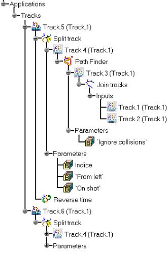
140 Page 140
 What you need to do: Right-click the track, select the track object item and select the Reverse time item from the contextual menu displayed.")

141 Page 141 About reversing time: Lets you modify the trajectory direction (by default, the direction is defined with respect to the creation order of the track positions) Use this functionality to simulate your track the other way round (i.e. a dismounting track becomes a mounting track) What you need to do: Right-click the track, select the track object item and select the Reverse time item from the contextual menu displayed. About joining tracks: Lets you merge several tracks. You can select more than two tracks at a time. What you need to do: Multi-select tracks, select the Join tracks item from the contextual menu: a new track is created. The initial tracks are swapped in no show space Be careful because the result depends on the tracks selection order. See: example below Two tracks to be merged Result 1 Result 2


142 Page 142 About splitting a track: Lets you split a track into two new tracks. Two selections are available: if you select a point on the original track, the result will be two continuous tracks. if you select segments, the result will be two discontinuous tracks. What you need to do: Right-click the track, select the track object item and select the Split track item from the contextual menu. Now, select a point or a segment: two new tracks are created. The initial track is swapped in no show space. Example1: if selecting a point Example2: if selecting a segment


 as any other object, using the 3D compass.")
143 Page 143 About mirroring a track: Lets you apply a symmetry on a track using a plane of your choice. Define the required plane using the 3D compass. See example below. Position the 3D compass wherever you want, this position defines the symmetry plane with respect to the uov plane of the 3D compass. What you need to do: Right-click the track, select the track object item and select the Mirror track item from the contextual menu: a new symmetrical track is created and the initial track remains displayed in the geometry area About transforming a track: Lets you reposition the entire tracks (translate and/or rotate) as any other object, using the 3D compass. Drag and drop the 3D compass handle onto a track, then move the compass as you wish. Note: you can select a track or multi-select tracks and their related objects
144 Page 144 About launching a path finder on a track: Lets the system find automatically a dismounting path without any collisions. This capability uses an input specification (that is the initial track) and results in a new track. The path finder uses the original positions on the track to optimize the path. What you need to do: Select a track, click the Path finder icon in the DMU Check toolbar and click Apply: a new track is created, the initial track is swapped in no show space. Note: The Update track capability is very useful when performing a path finder. Any modification of the initial track launches a new path finder computation, the resulting track is updated accordingly. For more information about path finder, please read Path Finder section About smoothing: Lets the system automatically get rid of the unnecessary positions without introducing any collisions. This capability uses an input specification (that is the initial track) and results in a new track. What you need to do: Select a track, click the Smooth icon in the DMU Check toolbar and click Apply: a new track is created, the initial track is swapped in no show space. Note: The "Update track" capability is very useful when smoothing. Any modification of the initial track launches a new smooth computation, the resulting track is updated accordingly. For more information about smooth, please read Using the Smooth Command
145 Page 145 About launching a swept volume operation: Lets the system compute automatically the swept volume of a moving part along a track. This capability uses an input specification (that is the initial track) and results in a new swept volume which can be saved in different format types. Select a track, click the Swept volume icon in the DMU Simulation toolbar and click Apply: a new swept volume is created, the initial track is remains displayed. Note: The "Update track" capability is very useful when performing a swept volume. Any modification of the initial track launches a new swept volume computation, the resulting swept volume is updated accordingly. For more information about swept volume, please read Swept Volume section


146 Page 146 Analyzing in Track Context This task depicts how analyses are bound to tracks and how are the analyses used. Open the ANALYZE_TRACKS.CATProduct document. A track is already defined on the DEMO_CGE_CHAINSAW_BODY_TANK_RSIDE.1 object and interferences specifications are also defined in your document. 1. In the specification tree or in the geometry area, double-click Track.1 2. In the Track dialog box, click the "clash on track" button to display the analysis list. This button is grayed out if there aren't any analyses (interferences and distances) defined in your document
147 Page 147 But you can still perform automatic clash detection (without defining a clash specification): select your track and click the arrow within the Clash Detection icon from the DMU Check toolbar. Undock the toolbar if necessary. Activate Clash detection (on or stop modes), then simulate your track. Please refer to Validating Positions Automatically The Analysis dialog is displayed: 3. Click the Bound item to link Distance.1 and Interference.1 to Track.1. (Click the Bound item again to cancel the operation) Note: you can also select the analyses one after the other or multi-select them to bound them
 click OK in the Analysis dialog box.")
148 Page Click the State item if you want to change the detection mode (stop, on, off). The default mode is "Stop". Read More about clash detection in track context to better understand the combination of the analyses states and the clash detection modes 5. When satisfied (i.e. keep the default state Stop) click OK in the Analysis dialog box. A Dynamic clash detection information message is displayed letting you activate automatic clash detection 6. Click Yes to activate the Clash Detection The Stop mode is automatically activated products are highlighted : the simulation stops at the first clash, the 7. Click the Play forwards button in the Player The results are shown below: The product in clash is highlighted and the distance is calculated at each position.


149 Page 149 More about clash detection in track context:
 and analyses are bound and set to on, there is no calculation. Example: you have a track containing analyses (see bound tab-step.")
150 Page 150 specifies the states in the Analysis dialog box (stop is the default mode) specifies the clash detection modes ( clash detection toolbar) Note: if the detection mode is set to off (by default) and analyses are bound and set to on, there is no calculation. Example: you have a track containing analyses (see bound tab-step.3) (let's say two interferences) Interference 1 is set to stop Interference 2 is set to on Clash detection mode selected: (Stop mode) You simulate your track, the track is stopped when interference 1 is detected, interference 2 is calculated and displayed but does not stop the track simulation.
151 Page 151
152 Page 152 Exporting and Importing Tracks in Neutral Format About XML: XML (Extensible Markup Language) is a standard format that can be used as a simple way to exchange data. The advantage of using this format to import and export tracks is two-fold: Results and how the results are presented are two separate entities, so you can customize your own style sheet to present the results the way you want without impacting the results themselves. XML makes documents smarter and more portable. You can for example export and publish the same results to a web browser as well as to your company database. Note: XML processors letting you generate HTML pages corresponding to the XML file and style sheet are available on the market. This task show you to import and/or export track definitions in neutral format and how to use them. Two neutral formats may be exported:.xml and a text format, which has a.fitting extension. The text file provides information on what object the track is associated with and a description of each recorded shot. If the track- associated object is a product or a shuttle, additional information also includes: file path or VPM identifiers to the associated parts, and relative position of parts to the shuttle axis. Open the EXPORT_V5_TRACK.CATProduct document. 1. Select Track.2 either in the specification tree or in the geometry area

153 Page Select Tools->Simulation->Track File Export The Track File Export Track dialog appears: 3. Enter a meaningful name and select.xml format or.fitting from the Save as Type drop-down list: 4. Open the EXPORT_V5_TRACK.xml document in an internet browser you have just created This is what you obtain:

154 Page Now open the IMPORT_V5_TRACK.CATProduct document. Select Tools->Simulation->Track File Import

155 Page Select EXPORT_V5_TRACK.xml document in the samples folder This is what you obtain:
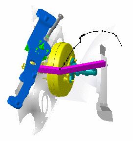
156 Page 156
157 Page 157 Editing Time Line in Tracks When creating a track, the duration of each segment is, by default, calculated to keep a uniform speed over the whole track. It is now possible to change the duration of each segment, you can edit segment duration within the Track dialog box using the More button modify quickly the segment duration using drag and drop capability enter a precise value to modify this duration. This task show you to edit time line in track command for demo purposes. It can be useful to differentiate simulation segments editing each and every segment duration (i.e. speeding up or slowing down depending on the part you are being dismounting Open the CHAINSAWAT.CATProduct document. 1. Double-click Safety_Handle_Track (Track.1) either in the geometry area or in the 2. specification tree. Click the Parameters icon in the Player The Player Parameters dialog box is displayed: 3. Enter 5 s in the sampling step field 4. Play your track simulation using the play forward button from the player 5. Click the more button


158 Page 158 You are going to reduce the last segment duration 3. Select the last segment 4. Drag the last shot which duration is s to approximately Drag the first shot from to approximately 140 or if you want a finer accuracy: enter the value in the shot time field and press ENTER key.

159 Page Play your track simulation again using the play forward button from the player. If you are not satisfied with the result, modify the duration again. The track simulation is slow at the beginning and speeds up in the end. Keyboard Shortcut Select + CRTL key: lets you drag each and every segment of the time line representation without changing the global duration

160 Page 160 Copying and Pasting Tracks This task illustrates the use of the copy/paste capability. It can be very useful to apply the same track to another object which has the same dismounting path. Open the COPY_PASTE_TRACKS.CATProduct document. A track is already defined on the DEMO_CGE_CHAINSAW_BODY_TANK_RSIDE.1 object 1. In the specification tree or in the geometry area, select the track you wish to copy. In our example, select Track.1 2. Put the data you have selected in the clipboard. To do this, either click the Copy icon, select the Edit- >Copy command or select the Copy command in the contextual menu. 3. Select Tracks item under Applications in the specification tree. 4. Now either click the Paste icon, select the Edit->Paste command or select the Paste command in the contextual menu. This operation recovers the data previously put in the clipboard.
 to modify the object selection The Track dialog box along with the DMU recorder and player are")

161 Page 161 The track is pasted: 5. Double-click the pasted track, in our example:track.1(track.2) to modify the object selection The Track dialog box along with the DMU recorder and player are displayed: 6. In the Track dialog box, click the Object selection field The Track positioning dialog box appears: In our example, we will keep the default option set For more detailed information, please refer to Track Editor and Recorder


162 Page Select DEMO_CGE_CHAINSAW_BODY_TANK_LSIDE.1 object either in the specification tree or in the geometry area This is what you obtain: The two tracks are linked together. For example if you insert a new shot in the first track:
. The shot is automatically added in the second track. The two tracks are synchronized. 10.")

163 Page Double-click Track.1(Track.1) in the specification tree. 9. Click the Skip to end button When done click. in the Player and insert a shot (moving the 3D compass). The shot is automatically added in the second track. The two tracks are synchronized. 10. Click Ok to confirm your operation The modified position is kept when exiting the track command (dismounted). If you need to restore the initial position click the Reset icon from the DMU simulation toolbar. Remember you can break the link between the two tracks using the Break link functionality. You can access it via the track contextual menu
164 Page 164 Be careful because the result depends on the tracks selection order.
165 Page 165 Sequences Sequences have been enhanced: we recommend you to read the Sequence section in its overall to discover more about: scheduling actions: "iterative create last step and add" mode interface change for action duration Delay option Color and transparency actions To have a look, please click on the appropriate keyword in the What's New section (items under Sequences) About sequence capabilities: provides background information about sequence capabilities. Sequence editor: provides information about the sequence editor Display Gantt chart: provides background information about the Sequence Gantt Chart. Define a sequence: Click the Edit Sequence icon, add actions, sequence them, modify the actions duration if necessary. Click the Edit Analysis tab and add interferences and distances. When satisfied click OK.

166 About Sequence Capabilities Page 166 A sequence is a way to put together and schedule actions to perform simulations. Sequences are persistent and can be stored in your document. What is an action? Actions are entities of different nature organized within the sequence. They can be objects from the following list: tracks (camera tracks, product tracks, shuttle tracks, section plane tracks, light tracks) please refer to About Tracks Capabilities color and transparency actions ( ) visibility actions i.e. Show/Hide ( simulations (R6 simulations) sequences ( ) FEA Analysis Please read "DMU Engineering Analysis Review"- Animating Images mechanisms which can be simulated with laws Please read "Running Mechanisms within a Sequence" in the DMU Kinematics Simulator User's Guide About actions duration: Actions are characterized by a duration: i.e. Track duration is linked to the trajectory length About Visibility and color actions Using a a color/transparency action, you could only define an initial and a final state. This highlight aims at offering more capabilities for Color/Transparency actions based on the track model: recording of multiple states for the same action using the standard graphic properties toolbar. possibility to change the object on which is applied the action recording capabilities using the same Recorder tool than the track time edition of the action (possibility to change the duration of each segment). VB exposition The visibility or color actions are created in sequence context and their effects are seen only when you use the Player (in the sequence for instance) color and transparency actions have now a duration Visibility actions are instantaneous (duration=0) For more information, please refer to Defining a Sequence Initially the product looks like this: when creating a color action in the sequence, it becomes:

 If you need a delay, enter a value in the Action delay field (i.")
167 Page 167 Make sure though, you schedule this action properly using the Action Delay parameter (i.e. depending on the effect you want to obtain) The picture below gives you the various results after action creation according to the option set: This duration is recovered in the sequence but you can also apply a specific duration in sequence context. Example: Duration in the player of a sequence comprising two tracks: The two actions are scheduled to start one after the other (see: sequencing modes) Beginning End About Action Modification You can modify the action duration, all you need to do is: select the action in the Actions in Sequence list Enter the new value in the action duration (i.e. 200) If you need a delay, enter a value in the Action delay field (i.e. 400) You can use the Reset button to swap to the default action value (intrinsic duration)

 Simultaneous mode")
168 Page 168 About sequencing Sequencing aims at defining a time frame within which the actions are scheduled. Two sequencing modes are available: actions start together (simultaneous mode) actions start right one after the other (consecutive mode) Simultaneous mode Beginning Middle End Consecutive mode Beginning Middle End


, Click the Sequence icon, and add them using the")
 3.")
169 Page 169 You can combine the two modes and modify the scheduling at any time. Sequences lets you put together existing actions, anyway, you can easily create a new action on the fly and add it in the current sequence. This capability lets you edit actions in context and synchronize meeting points in different actions. The example below illustrates the two modes combination: Simultaneous mode Consecutive mode About Journaling/automation Sequences are journalized. You can generate a macro using Tools->Macro->Record... (see the Infrastructure user's Guide) Sequence creation: 3 methods are available to create sequences: 1. There are existing actions in your document (actions in session list), Click the Sequence icon, and add them using the arrow into the Action in sequence list and schedule them, using the sequencing tools (Refer to: Sequence editor) 2. Open an empty sequence and create actions on the fly (the sequence editor remains opened) 3. Combine the two methods (1. and 2.) Sequences created in this manner are persistent and can be stored in the document. They are listed as separate entities in the specification tree and can be selected at any time and modified.
 graphic attributes ( show/hide, colors, transparency) You can also manage time with Gantt chart Let's look at it more carefully: The Edit Sequence dialog box comprises of two tabs: Edit Action")
170 Sequence Editor Page 170 The sequence editor lets you manage and simulate actions from the following: moving objects (part, camera,...) graphic attributes ( show/hide, colors, transparency) You can also manage time with Gantt chart Let's look at it more carefully: The Edit Sequence dialog box comprises of two tabs: Edit Action tab Edit Analysis tab The Edit Action tab lets you perform the following operations: Add/remove actions using the green arrows 1. Select an action in the "Action in session" list and click. The action is added in the sequence list. See example below:

 Create last step and add option: creates a last step and add the selected action into it.")
171 Page Select an action and click. The action is removed from the "Action in Sequence" list Note: If you multi-select actions in the session list and click the Add button, the actions are added in simultaneous mode. Customize the add mode settings: (1) Create last step and add option: creates a last step and add the selected action into it.(default mode) (in consecutive mode) (2) Add in last step option: lets you add an action in last step (in simultaneous mode) A new add mode appears (3) Iterative create last step and add option: lets you add the actions in consecutive steps ( )


172 Page 172 (1) (2) (3) Sequence actions using: if working in consecutive mode Move up: moves up a selected action Move down: moves down a selected action if working in simultaneous mode Merge up: merges the selected action up Merge down: merges the selected action down Note: remember you can combine the two modes within the same sequence. Please read About Sequence Capabilities Customize the action duration action duration: the numerical field lets you enter a specific duration for an action (this capability enables to simulate the same action with a different time scaling) reset duration lets you reset the selected action to its intrinsic duration Note: you can enter a specific duration for all action types except visibility actions which are instantaneous (duration=0)


173 Page 173 A new option is available : action delay: lets you delay the starting time of an action (i.e. it is now possible to overlap two actions) For instance, two tracks within the same sequence step can be synchronized, in order to achieve passing by specific waypoints simultaneously. For all actions contained in the sequence, the delay is a time attribute, just like their duration. It means the action will start with respect to the specified delay with the theoretical beginning of the step, which the action belongs to. Valid delay values are zero or positive. The actions appear in the "Action in sequence" list, they are scheduled in steps and their duration and delays are displayed. Note: To apply a delay to an action or modify it, all you need to do is select the required action in the Action in session list and enter a value in the Action delay field: Also read : About actions duration Now click the Edit Analysis tab:
174 Page 174 The Edit Analysis tab lets you perform the following operations: Add/remove interferences or distances using the green arrows 1. Select an analysis in the "Analyses in session" list and click add. The action is added in the sequence list. 2. Select an analysis in the "Analyses in Sequence" list and click remove Note: you can add existing interferences or distances or create them on the fly ( in this case they are automatically displayed in the "Analyses in session "list Set the clash detection mode Set all inactive option: (default mode) as you simulate your sequence, the detection is set to off, the interferences and/or distances defined in your sequence are not taken into account Set all active option: as you simulate your sequence the detection is set to on, the interferences and/or distances defined in your sequence are taken into account Set all stop option: as you simulate your sequence, the detection is set to stop (on collision), the simulation stops when an interference defined in your sequence is detected. The distances defined remain active. About Editing an action and analysis Double-click actions, interferences, distances to display the dedicated editor. Perform the required modifications, the modifications are automatically taken into account in the Edit Sequence dialog box.

175 Page 175 Displaying Gantt Chart This task shows you how to display the Gantt Chart viewer. A Gantt chart allows users to do a basic, overall cycle-time analysis for a set of actions. The Gantt chart visualization is based on the cycle time parameter defined in each action. About Gantt Chart: The Gantt chart is another way to visualize your sequence. Note that you cannot modify the action duration using the Gantt window. A Gantt chart is bar graph of a sequence. It shows start and stop times as well as dependencies. The Gantt chart is a 2D view of the sequence process. Open the CHAINSAWAT.CATProduct document A sequence is defined 1. Select a sequence in the specification tree: for instance Sequence.4 Gantt Chart for multiple sequences in a single Gantt Chart are not supported 2. Select Window->New Gantt Chart Window

, provides a visual indication of the current time during the execution.")
176 Page 176 The Gantt chart window is displayed: Let's describe it more carefully: The left frame of the Gantt chart lists each of the individual actions and /or analyses that exist in your document, displaying the duration, start time and end time for each. The right frame provides a graphical representation of each action or analysis (along the line of time) which also indicates the start, duration and end of each. A dashed vertical line in the right window (called the Time Line), provides a visual indication of the current time during the execution. You can easily modify the action duration within the Gantt Chart, stretching the action graphical representation, the Gantt Chart as well as the Edit sequence dialog box are automatically updated. For instance, double-click a sequence in the specification tree. You are in the sequence command. Then select Window->New Gantt Chart Window:
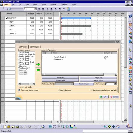
177 Page 177

178 Page 178 It does work, the other way round: modifying the action duration within the Edit Sequence updates the Gantt Chart window automatically
 in the action in session list and click. 3. Select Track.1 (Track.2) in the action in session list and click.")
179 Defining a Sequence Page 179 This task shows you how to define a sequence Open the DEFINE_SEQUENCE.CATProduct document. Tracks are already defined 1. Click the Edit Sequence icon in the DMU Simulation toolbar The Edit Sequence dialog box is displayed 2. Select Track.1 (Track.1) in the action in session list and click. 3. Select Track.1 (Track.2) in the action in session list and click. The Sequence.1 is identified in the specification tree
 in the")
")
180 Page 180 you want them to start together 4. Click Merge Up button The two actions will start together Note: you could have selected both (simultaneous mode) in the action in session list. 5. Check the "Add in last step" option in the Edit Sequence dialog box (Create last step and add option is set by default) 6. Add a color action (you are going to create it on the fly), for this Click the Color action icon in the DMU Simulation toolbar The Color Action edition dialog box appears


181 Page 181 You can alter the name of the color action by entering one in the Name field, or you can accept the default name provided. 7. Select Handle.1 either in the specification tree or in the geometry area The Graphic Properties toolbar appears 8. Select a color of your choice using the arrow and combo list. For instance blue 9. Click Record 10. Set the transparency, for this: click the Edit button in the color action dialog box select the Graphic tab in the Properties dialog box displayed check the transparency option if needed, and move the slider as desired Note: you can access the Properties dialog box at any time to change color, transparency. The Graphic Properties toolbar a quicker way to modify graphic properties.


182 Page Click Apply, when done, click close to exit the Properties dialog box 12. Click Record 13. Click Ok in the Edit Color Action dialog box when you are satisfied. The color action is automatically added in the action in the sequence and identified in the specification tree

 and click.")
183 Page Modify the action duration if necessary For more detailed information, please read: About Action Modification Enter 200 in the Action duration field 15. Select the Color Action.1 in the action list and modify its delay: enter 400 in the Action delay field 16 Play your sequence if needed using the Player Now add analyses in your sequence for validation purposes 17. Click the Edit Analysis tab 18. Multi-select the existing analyses (i.e. Distance.1 and Interference.1) and click. Note: you can create and add analysis specifications on the fly. You can also edit existing analysis specifications, double-clicking them in the "Analyses in sequence" list 19. Click Set all active button

184 Page Click Ok in the Edit Sequence dialog box when satisfied. 21. Select your sequence in the specification tree and click the player icon. 22. Simulate your sequence using the Player buttons. 23. If you need to restore the initial positions, click the Reset icon. 24. Open the DEFINE_SEQUENCE_RESULT.CATProduct to check your result
185 Page 185 Generating Animations Generate a video using DMU dedicated tool (using Tools->Simulation->Generate Video), Generate a video using standard tools (using Tools->Image->Video), Please also read Generate an Animation
186 Generating a Video Using Standard Tools Page 186 This task shows you how to generate a video file selecting Tools->Image->Video... Open CHAINSAWAT.CATProduct document. 1. Select Sequence.4 in the specification tree 2. Open a camera window, select Window->Camera window->camera Select Window->Tile Horizontally...

187 Page Multi-select the tracks in the specification tree and click the Hide/Show icon, or select the View- >Hide/Show->Swap Hide/Show command. The track objects are no longer displayed: they have been transferred into the No Show space. You are now ready to generate a film in AVI format 4. Select Tools->Image->Video to display the Video Recorder dialog box Set Up the Capture Session Click the Recording button to access the Video Properties dialog box which lets you set up the video capture parameters prior to recording the video Choose the Video File Format and Location in our example select Microsoft AVI (Windows) Specify which part of the screen to record Setting Movie Replay Parameters Click OK in the Video Properties dialog box to start the recording. Please read Recording Interactions in Video Format in the Infrastructure User's Guide 5. Run your sequence simulation with the Player 6. Click Stop
188 Page 188 Explode You can use the explode functionality either to understand better the structure of your assembly and analyze the dismount capability or to obtain a printed document of your exploded product for further analysis. Explode a product: Select a product, then click the explode icon. Select the required explode type and depth setting. Click Apply. Explode a constrained assembly: Select a product, then click the explode icon. Set the explode type to constrained, when done click Apply. Explode a shuttle: Select a shuttle, then click the explode icon. Select the required explode type and depth setting. Click Apply. The interest of this operation lies in the ability of viewing all components separately within the same plane. Now, you can print the exploded view. Generate a Sequence from an exploded view: Select a product, then click the explode icon. Select the required explode type and depth setting. Check the Generate a sequence option.click Apply.
189 Page 189 Exploding a Product This task illustrates the use of the Explode capability. Exploding the view of an assembly means separating the components of this assembly to see their relationships. At any time though, you can check the product structure via the specification tree. The explode capability allows you to fully understand the product structure in a 3D context. Open the CHAINSAW.CATProduct document. 1. Select Product1 in the specification tree. 2. Click the Explode icon. The Explode dialog box is displayed. Product 1 is the assembly to be exploded. The Depth parameter lets you choose between a total (All levels) or partial (First level) exploded view. 3. Set All levels if not already set. 4. Set 3D as explode type. You can now generate a sequence from the exploded view, all you need to do is click the Generate Sequence checkbox before launching the explode operation. For more detailed information refer to Generating a Sequence from an Exploded View 5. Click Apply to perform the operation.

190 Page 190 The Scroll Explode field gradually displays the progression of the operation. The application assigns directions and distances. Once complete, the assembly looks like this: The interest of this operation lies in the ability of viewing all components separately. 6. If you click, you go back to the product structure level which corresponds in this case to the sub-entities: engine, handle, sword as shown below:


191 Page 191 You can easily move products within the exploded view using the 3D compass. 7. Click OK to confirm the operation or click Cancel to restore the initial view. Note: If you click OK, the following warning message is displayed as the exploded view is kept when exiting the command. In this case, if you need to restore the initial view click the Reset icon.
192 Page 192
193 Page 193 Exploding a Constrained Assembly This task shows how to explode an assembly taking into account the assembly constraints. This Explode type is applicable only to specific cases: when the assembly is assigned coincidence constraints: axis/axis plane/plane Open the EXPLODE_CONSTRAINED_ASSEMBLY.CATProduct document. 1. Click the Explode icon. The Explode dialog box is displayed. 2. Wheel Assembly is selected by default, keep the selection as it is. You can also use the drag and drop capability (drag the explode icon and drop it onto the required product in the specification tree. The Depth parameter lets you choose between a total (All levels) or partial (First level) exploded view. 3. Keep All levels set by default. 4. Set the explode type. 3D is the default type. Keep it. You can now generate a sequence from the exploded view, all you need to do is click the Generate Sequence checkbox before launching the explode operation. For more detailed information refer to Generating a Sequence from an Exploded View 5. Click Apply to perform the operation. Note that you can move products within the exploded view using the 3D compass.

194 Page 194 The manipulation toolbar is also available once you move an object with the 3D Compass. The Scroll Explode field gradually displays the progression of the operation. The application assigns directions and distance. Once complete, the resulting exploded view looks like this: You are not satisfied with this result as the nuts are not correctly positioned. The constraints are not respected. Replay the scenario selecting the constrained type. 6. Still in the Explode dialog box, set the constrained type. 7. Define a fixed product: in our example select the Rim1 either in the specification tree or in the geometry area


195 Page Click Apply to perform the operation. Once complete, the resulting exploded view looks like this: The nuts are correctly positioned, the exploded view corresponds more to the reality and to a technical documentation.
196 Page Click OK to validate the operation or click Cancel to restore the original view. Note: If you click Ok, the following warning message is displayed as the exploded view is kept when exiting the command. In this case, if you need to restore the initial view click the Reset icon. The explode functionality aims at understanding better how the assembly is structured. You can use it for further purposes: creating scenes, print, keep the exploded view as archive document or generate a drawing (please refer to Create Scenes in the DMU Navigator User's Guide)

 or partial (First level) exploded view. 3. Set first level if not already set. 4.")
197 Page 197 Exploding a Shuttle This task shows how to explode a shuttle. This time, you need to print the exploded view to define a bill of material for instance Open the EXPLODE_SHUTTLE.CATProduct document. 1. Click the Explode icon. 2. Select the shuttle you need to explode in the specification tree or in the geometry area. You can also use the drag and drop capability (drag the explode icon and drop it onto the shuttle.1 in the specification tree. The Explode dialog box is displayed : The Depth parameter lets you choose between a total (All levels) or partial (First level) exploded view. 3. Set first level if not already set. 4. Set 2D to define the explode type. The exploded view is set to the screen plane. You can now generate a sequence from the exploded view, all you need to do is click the Generate Sequence checkbox before launching the explode operation. For more detailed information refer to Generating a Sequence from an Exploded View

198 Page Click Apply to perform the operation. The Scroll Explode field gradually displays the progression of the operation. The application assigns directions and distance. Once complete, the resulting exploded view looks like this: The interest of this operation lies in the ability of viewing all components separately within the same plane.

199 Page Click OK to validate the operation or click Cancel to restore the original view. Note: If you click Ok, the following warning message is displayed as the exploded view is kept when exiting the command. In this case, if you need to restore the initial view click the Reset icon. 7. Now you can print the exploded view. Select File->Print command to display the Print dialog box Once you select the desired settings, press the preview button and click OK
200 Page 200
201 Page 201 Generating a Sequence from an Exploded View This task shows how to generate a sequence from an exploded view Open the CHAINSAW.CATProduct document. 1. Click the Explode icon. The Explode dialog box and the manipulation toolbar are displayed. 2. Product.1 is already selected, keep the selection as it is. You can also use the drag and drop capability (drag the explode icon and drop it onto the required product in the specification tree. The Depth parameter lets you choose between a total (All levels) or partial (First level) exploded view. 3. Keep All levels set by default. 4. Set the explode type. 3D is the default type. Keep it. 5. Click the Generate Sequence checkbox 6. Click Apply to perform the operation. Note that you can move products within the exploded view using the 3D compass. The manipulation toolbar is also available once you move an object with the 3D Compass. 7. Click Ok in the Information dialog box The Scroll Explode field gradually displays the progression of the operation. The application assigns directions and distance. Once complete, the resulting exploded view looks like this:

202 Page Still in the Explode dialog box, click Ok The following warning message is displayed, click Yes This is what you obtain: the tracks are created and displayed in the geometry area. A sequence is automatically created and displayed in the specification tree
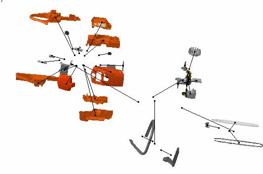
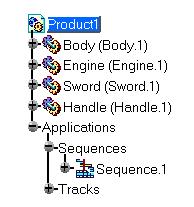
203 Page 203
204 Page Double-click Sequence.1 in the specification tree. Play your sequence as desired. The created sequence reflects exactly the product structure (simultaneous or consecutive tracks are synchronized with the product structure) The picture below shows you how the generated sequence is organized in a Gantt chart
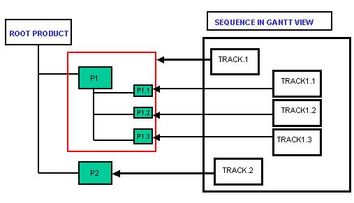
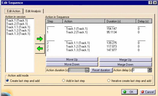
205 Page 205
206 Page 206 Advanced Tasks DMU Fitting Simulator provides easy methods to define a multi-shuttle that will then be recorded and replayed. Simultaneously to the replay or after, users can analyze the interferences and distance assigned to the assembly. Using Multiple Shuttles Using Track and Sequence Capabilities Converting a Simulation into a Sequence Path Finder Validating a Motion Swept Volume
207 Page 207 Using Multiple Shuttles This chapter shows how to use multiple shuttles. Defining Several Shuttles Defining a Shuttle Made of Shuttles Recording a Multi-Shuttle Simulation Defining a Shuttle Motion using another Shuttle as Reference Defining a Shuttle Motion Using a Product as Reference Adding a Shuttle in a Simulation

208 Page 208 Defining Several Shuttles This task shows how to define/edit two shuttles. The final purpose of defining these shuttles to dismount the engine. First, perform an explode of product 1 to understand better how to dismount the engine. Open the SEVERAL_SHUTTLES.CATProduct document. Let's create a first shuttle. 1. Click two objects (for instance, STARTINGHOUSE.1 and STARTHANDLE.1) in the specification tree as shown below. 2. Click the Shuttle icon. The Edit Shuttle dialog box and the Preview window appear. 3. Press OK to confirm your operation.
or click the shuttle icon first and select Group1 afterwards. The Edit Shuttle dialog window appears (Shuttle. 2). 5. Press OK. 6.")
209 Page 209 The Shuttle is created and identified in the specification tree. Let's create a second shuttle based on an existing group 4. You Drag the Shuttle icon.and drop it onto the existing group in the specification tree (Group1)or click the shuttle icon first and select Group1 afterwards. The Edit Shuttle dialog window appears (Shuttle. 2). 5. Press OK. 6. The second shuttle is created and identified in the specification tree.


210 Page You can edit the shuttles independently. For more information, please refer to Editing a Shuttle. One manipulator appears on each shuttle. These manipulators will allow you locating and moving the shuttles to the desired location.

211 Page 211 Defining a Shuttle Made of Shuttles This task shows how to prepare a dismounting operation defining a shuttle made of shuttles. You decide to dismount the whole clutch system included in the engine group. Three shuttles shuttles are defined in our sample: Drum-Shuttle Hub-Shuttle Shoe-Shuttle In our example, you no longer need to define a fourth shuttle containing the required objects but integrate the Hub-shuttle and Shoe-Shuttle into the Drum-Shuttle. As you replay the simulation, the three shuttles are single entities but if you need to move the whole clutch system, you will only move the Drum-Shuttle. Open the ENGINE_WITH_SHUTTLES.CATProduct document. Please refer to Defining a Shuttle and Editing a Shuttle. You can use the drag and drop capability create shuttles in existing shuttles. Using drag and drop can help to prepare your dismounting operation more carefully. You can reorganize your assembly into a "shuttle" specification tree which corresponds to a logical dismount operation. The "shuttle" specification tree reflects your product specification tree and the logical dismount procedure. The shuttles are created and identified in the specification tree


212 Page Multi-select the Hub-Shuttle and the Shoe- Shuttle 2. Drag your selection onto the Drum-Shuttle object You created a shuttle made of Shoe-Shuttle and Hub-Shuttle which reflects the logical assembly. 3. Double-click the Drum-Shuttle in the specification tree The Edit Shuttle dialog box and Preview window are displayed 4. Move the Drum-Shuttle The Hub-Shuttle and the Shoe-Shuttle move alongside


213 Page Click Ok Edit Shuttle dialog box to exit. 6. Double-click the Hub-Shuttle. 7. Move the Hub-Shuttle as required 8. Proceed in the same manner for the Shoe-Shuttle. This is what you obtain: You are now ready to record a simulation. Please refer to the next task Recording a Multi- Shuttle Simulation.
214 Page 214

215 Page 215 Recording a Multi-Shuttle Simulation This task shows how to simulate a more than one shuttle fitting simulation. You are going to record a simulation with three shuttles. Open the SHUTTLES_MADE_OF_SHUTTLES.CATProduct document. 1. Multi-select in the specification tree: Drum-Shuttle Hub-Shuttle Shoe-Shuttle 2. Click the Simulation icon. The Edit Simulation dialog box is displayed

216 Page 216 The 3D compass lets you move the shuttle 3. Move the Drum-Shuttle to the desired location via the manipulator. 4. Click the Insert switch to record the shot. Insert means that you record and insert shots inside the scenario. The initial location of the shuttle is automatically recorded as a starting shot. If you need to reposition the shuttle, please delete the first position or modify it

217 Page Now select the Hub-Shuttle. Three possibilities are available: Select the Hub-Shuttle in the specification tree Select the Hub-Shuttle axis in the geometry area Select the product in the geometry area The 3D compass snaps onto your selection 6. Move the Hub-Shuttle to the desired location using the 3D compass. 7. Click the Insert switch and record the desired shot. 8. Select the Shoe-Shuttle axis. 9. Drag the Shoe-Shuttle to the required location. 10. Record this motion clicking the Insert switch. 11. Press OK in the Edit Simulation dialog box You recorded the motion of the three shuttles The simulation object is created and identified in the specification tree


218 Page You can now create a replay. For more information, please refer to Generating a Replay. To analyze an object and its related objects under the form of a specification tree or in the 3D, select the current selection icon from the Simulation toolbar or select Analyze - >Current Selection Panel from the menu bar. The Current Selection Panel dialog box appears as follows:
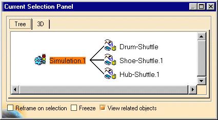
219 Page 219
220 Page 220 Defining a Shuttle Motion Using Another Shuttle as Reference This task shows how to define a shuttle motion using another shuttle as reference. Open the SHUTTLE_REFERENCE.CATProduct document. You decide to dismount the starthandle. You created two shuttles: Starthandle-Shuttle Startinghouse-Shuttle For more details, please refer to Defining a Shuttle. You are going to record the motion relative to another shuttle. 1. Double-click the Startinghandle-Shuttle in the specification tree. 2. Click the Reference field from the Edit Shuttle dialog box, select Startinghouse-Shuttle in the specification tree. 3. Click Ok to confirm your operation 4. Multi select Starthandle-Shuttle and Startinghouse-Shuttle either in the specification tree or in the geometry area. 5. Select Insert->Simulation. 6. Select Starthandle-Shuttle in the specification tree and click Insert. 7. Select Startinghouse-Shuttle and click Ok to end your simulation recording.


221 Page 221 The Starthandle-Shuttle and Startinghouse-Shuttle motions are synchronized. The Startinghouse- Shuttle moves relatively to the Starthandle-Shuttle. Note that when you define a reference shuttle in this manner the specification tree is updated as if you had defined a shuttle made of shuttles.

222 Page 222 Defining a Shuttle Motion Using a Product as Reference This task shows how to define a shuttle motion using a product as reference. In our example, we study the dismounting of the starthandle. The Chainsaw design is still subject to changes and you know the startinghouse is going to be repositioned because the engine position is not defined yet. You need the starthandle (shuttle) to be associative with the startinghouse (reference product) within the simulation to keep the consistency of the motion. The capacity to select a product as reference will keep your simulation consistent after design changes (here on the startinghouse) You already defined the dismounting path of the starthandle Open the CHAINSAW1.CATProduct document. You defined a simulation reflecting the dismounting path of the starthandle. You defined a shuttle on the starthandle Shuttle.1 For more details, please refer to Defining a Shuttle. 1. Double-click Simulation.1 in the specification tree. The Edit Simulation dialog box and Preview window appear 2. Modify the interpolation value as desired. For example: 0.04

223 Page Click the Play Forward button. The recorded motion is replayed. Now the startinghouse has been repositioned 4. Open CHAINSAW2.CATProduct. The design has changed and the shuttle motion is no longer valid.

224 Page Double-click Shuttle.1 in the specification tree 6. In the Reference field from the Edit Shuttle dialog box, the CHAINSAW_BODY_STARTINGHOUSE.1 is selected. 7. Click Ok 8. Double-click the Simulation.1in the specification tree 9. Replay your simulation. The shuttle motion is updated. The design change is taken into account.
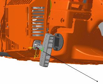
225 Page 225
 1. 1. In the specification tree, click Shuttle.1. 2.")

226 Adding A Shuttle in a Simulation Page 226 This task shows how to add a shuttle in a simulation. In our example you need to move first the starthandle to dismount the startinghouse. Open the ADDING_SHUTTLE.CATProduct document. You created a shuttle with the startinghouse. (referred as shuttle.1) In the specification tree, click Shuttle Click the Simulation icon. The Edit Simulation dialog box and Preview window appear. The starting shot (shuttle initial position) is automatically recorded. 3. Move the shuttle to the desired location with the manipulator. 4. Click the insert switch and record the desired shots You need to move the starthandle, for this: create a shuttle without exiting the simulation command 5. Click the Shuttle icon.

227 Page Select DEMO_CGE_CHAINSAW_BODY_STARTHANDLE.1 either in the geometry area or in the specification tree (expand the Body item) 7. Click OK to confirm the shuttle creation. 8. Click Edit simulation objects in the Edit Simulation dialog box as shown below: The Edit Simulation Objects dialog box is displayed. 9. Click Add and select shuttle.2 in the Select dialog box and click OK 10. Click OK in the Select dialog box. 11. Click OK in the Edit Simulation Objects dialog box to confirm your operation.


228 Page 228 The shuttle.2 is identified in the specification tree 12. Move the shuttle.2 to the desired location with the manipulator 13. Click the insert switch and record the desired shots. You can dismount the startinghouse.
229 Page 229 Using Track and Sequence Capabilities This chapter aims at illustrating the useful combination of tracks and sequences throughout a step-bystep dismounting scenario: Road Map Phase 1: Dismount the Chainsaw Handle Creating a Chainsaw_Handle Shuttle Performing clash detection (standard clash tool) within the shuttle command. Hiding the gray handle object (CHAINSAW_BODY_HANDLE.1) Resetting products position Creating a Chainsaw handle shuttle track Phase 2: Illustrate the dismounting operation Displaying the hidden gray handle (CHAINSAW_BODY_HANDLE.1) Creating a visibility action on the gray handle object Defining a sequence containing the handle shuttle track and the created visibility action Running the defined sequence Phase 3: Finalize the dismounting operation: Editing the sequence Creating a track on CHAINSAW_BODY_CLUTCHCOVER.1 (Clutchcover_Track) within the sequence command Running the sequence Modifying action duration and scheduling within the sequence Running the sequence again Modifying the DMU player parameters Creating a track on CHAINSAW_BODY_SAFETYHANDLE.1
230 Page 230 Phase 4: Generate a film Creating a camera (using the View ->Named Views...) with 3 different viewpoints focusing on CHAINSAW_BODY_SAFETYHANDLE.1, on CHAINSAW_BODY_CLUTCHCOVER.1 and on the Chainsaw_Handle Shuttle Playing the created camera Defining a camera track Defining a new sequence Customizing the player parameters Editing the camera track Defining a sequence and replay it (in a camera window Window ) Multi-selecting and Hiding the current tracks Generating a Film (in AVI format) using Tools->Image->Video..

231 Page 231 Dismounting the Chainsaw Handle This scenario is aimed at dismounting the chainsaw handle: each of the following products belongs to the body set. For this you will need to perform various operations such as: Creating a Handle_Shuttle Performing clash detection Hiding handle Resetting products Creating a Handle_Shuttle track Open the CHAINSAW.CATProduct document. 1. Expand the Body node, and select in the specification tree or in the geometry area: (CHAINSAW_BODY_TANK_RSIDE.1) (CHAINSAW_BODY_TANK_LSIDE.1) (CHAINSAW_BODY_SAFETYTRIGGER.1) (CHAINSAW_BODY_PETROLCAP.1) (CHAINSAW_BODY_GASTRIGGER.1)


232 Page Click the Shuttle icon from the DMU simulation toolbar. The preview window gives the shuttle content

233 Page Give the shuttle a meaningful name (Handle_Shuttle for instance) 4. Now still in the shuttle command you are going to move the shuttle and perform a rough clash detection to prepare your dismounting path. Click the arrow within the Clash Detection icon Undock the toolbar if necessary. from the DMU Check toolbar. 5. Set the Clash detection to on 6. Move the shuttle. using the 3D compass. There is a collision between the Handle_Shuttle and the Clutch cover and the object BODY_HANDLE makes the dismounting operation impossible
")


234 Page 234 There is a collision between the Handle_Shuttle and the Clutchcover, besides, the object (CHAINSAW_BODY_HANDLE) makes the dismounting operation impossible. You are going to hide it but now validate the shuttle creation 7. Click Ok 8. The position is kept when exiting the command. In this case, you need to restore the initial view click the Reset icon.
 either in the specification tree or in the geometry area Click the Hide/Show icon, or select the View->Hide/Show->Swap Hide/Show command.")

235 Page Select the (CHAINSAW_BODY_HANDLE.1) either in the specification tree or in the geometry area Click the Hide/Show icon, or select the View->Hide/Show->Swap Hide/Show command. The object is no longer displayed: it has been transferred into the No Show space. In our example, the CHAINSAW_BODY_HANDLE.1 is no longer displayed. Now, you are ready to define a track for the created Handle_Shuttle object. For this, 10. Select Handle_Shuttle in the specification tree and click the Track icon from the DMU Simulation toolbar. The Track dialog box along with the DMU recorder and player are displayed:

236 Page Record your track shuttle, Move the 3D compass and click Record at each time position of your choice. If you double-click Record, the automatic insert mode is activated. Note: You can also use the Insert Key instead of clicking Record. Please refer to Recording a Track When satisfied, click Ok. 10. Rename your track with a meaningful name: in our example, choose Handle_Shuttle_Track. for this: Right-click Track.1 object in the specification tree and select the properties item from the contextual menu displayed Click the track tab. 11. Replay your Handle_Shuttle_Track using the VCR buttons from the dedicated player


237 Page 237 You created a shuttle and a track using this shuttle: Now, you are going to illustrate this dismounting operation.

238 Illustrating the Dismounting Operation Page 238 This scenario is aimed at illustrating the chainsaw handle dismounting operation For this you will need to perform various operations such as: Displaying the CHAINSAW_BODY_HANDLE.1 object Creating a visibility action on CHAINSAW_BODY_HANDLE.1 object Defining a Sequence containing the Handle_Shuttle_Track and the visibility action Running the sequence simulation using the Player. The CHAINSAW.CATProduct document is already open While, performing the chainsaw handle dismounting operation, you realized other objects needed to be dismounted such as the: CHAINSAW_BODY_HANDLE.1 object which makes the dismounting impossible (you already hide it) CHAINSAW_BODY_CLUTCHCOVER.1 CHAINSAW_BODY_SAFETYHANDLE.1 1. The CHAINSAW_BODY_HANDLE.1 has been transferred to the no-show area. 2. Click the No Show icon to display the contents of the no show area. CHAINSAW_BODY_HANDLE.1 object and transfer it back to the Show space using the Hide/Show icon. 3. Select CHAINSAW_BODY_HANDLE.1 object either in the specification tree or in the geometry area


239 Page Click the arrow within the color action icon to display the entire toolbar. Undock it if necessary, and click the visibility icon. 5. In the Edit Visibility Action dialog box displayed, keep the Hide selection option set as default and click Ok Now you are going to create a sequence 6. Click the Edit Sequence icon The Edit Sequence dialog box is displayed


240 Page Select Handle_Shuttle in the "Action in session" list and click. The action is added in the sequence list. 6. Select Visibility Action.1 in the "Action in session" list and click. The action is added in the sequence list. 7. Use the DMU Player to run your sequence. The dismounting operation is valid but you are still not satisfied with the result We need to dismount the CHAINSAW_BODY_CLUTCHCOVER.1 and therefore to create a Clutchcover track.
241 Page 241
242 Finalizing the Dismounting Operation Page 242 This scenario is aimed at illustrating the chainsaw handle dismounting operation For this you will need to perform various operations such as: Editing the sequence Creating a track on CHAINSAW_BODY_CLUTCHCOVER.1 (Clutchcover_Track) within the sequence command Running the sequence Modifying action duration and scheduling within the sequence Running the sequence again Modifying the DMU player parameters Creating a track on CHAINSAW_BODY_SAFETYHANDLE.1 Defining a color action on CHAINSAW_BODY_CLUTCHCOVER.1 Adding and scheduling this color action in the current sequence The CHAINSAW.CATProduct document is already open While, performing the chainsaw handle dismounting operation, you realized other objects needed to be dismounted such as the: CHAINSAW_BODY_HANDLE.1 object which makes the dismounting impossible (you already hide it) CHAINSAW_BODY_CLUTCHCOVER.1 CHAINSAW_BODY_SAFETYHANDLE.1 Still in the sequence command:


243 Page 243 Create a track on CHAINSAW_BODY_CLUTCHCOVER.1 in context 1. Click the track icon specification tree. from the DMU Simulation toolbar and select CHAINSAW_BODY_CLUTCHCOVER.1 in the The track dialog box is automatically updated and the new track is automatically created and added in the current sequence last step:


")
244 Page Move the 3D compass and double-click Record, the automatic insert mode is activated. 3. Click Ok in the track dialog box to confirm the track creation 4. Play your sequence using the play forward button from the DMU player Result: You are not satisfied with the sequence actions duration (it is too quick) nor with the scheduling 5. In the Edit Sequence dialog box still opened, select Handle_Shuttle_Track in the action duration field, enter 15.

245 Page Select Track.1 in the action duration field, enter 15 click Move up This what you should have 7. Play your sequence again using the play forward button from the DMU player Result: you are still not satisfied with the actions duration, you want your sequence simulation to run slower. You need to customize 8. Click the Parameters icon The Player Parameters dialog box is displayed: 9. Enter 0.2 s in the Time Step field 10. Play your sequence again using the play forward button from the DMU player

246 Page 246. The sequence is valid but you are still not satisfied with the result We need to dismount the CHAINSAW_BODY_SAFETYHANDLE.1 and therefore to create a Safety_Handle_Track. 11. Click the track icon specification tree. from the DMU Simulation toolbar and select CHAINSAW_BODY_SAFETYHANDLE.1 in the 12. Swap to Detach mode clicking the Attach/Detach icon from the Manipulation toolbar The 3D compass color changes: you are now in the Detach mode. The icon changes in the Manipulation toolbar 13. Click the Target icon from the Manipulation toolbar or drag and drop the icon onto the cylinder. Click when you are satisfied and swap to Attach mode Zoom out if necessary 15. Perform a rotation with the 3D compass and click Record, 16. Click Ok in the Track dialog box to end the the SAFETYHANDLE.1 track creation 17. In the Edit Sequence dialog box, select Track.2 in the action duration field, enter 15. click Move up until the action 7 (SAFETYHANDLE.1 track) is in step 1


247 Page 247 You want the CHAINSAW_BODY_CLUTCHCOVER.1 to become transparent during sequence simulation and before dismounting 18. Click the Color action icon in the DMU Simulation toolbar 19. Select CHAINSAW_BODY_CLUTCHCOVER.1either in the specification tree or in the geometry area 20. In the Graphic Properties toolbar displayed, select a color using the arrow and set the transparency too color: orange transparency: 25% 21. Click Ok in the Color action dialog box 22. In the Edit Sequence dialog box, click Move up twice and Merge up to schedule this color action in step 2 You make sure, the transparency action will be triggered at the beginning of the CHAINSAW_BODY_CLUTCHCOVER.1 dismounting ( Action 7//Track.2).
 Transparency action (step2) Visibility action (hiding the CHAINSAW_BODY_HANDLE.1) (Step 3) Handle_Shuttle_Track (Step 4) 24. Click Ok in the Edit Sequence dialog box.")
248 Page Replay your sequence using the DMU Player. Actions are scheduled in a logical way: CHAINSAW_BODY_SAFETYHANDLE.1 track (step 1) CHAINSAW_BODY_CLUTCHCOVER.1 track (step 2) Transparency action (step2) Visibility action (hiding the CHAINSAW_BODY_HANDLE.1) (Step 3) Handle_Shuttle_Track (Step 4) 24. Click Ok in the Edit Sequence dialog box. Right-click the tracks and select Properties from the contextual menu to rename them with a meaningful name. This is what you can obtain for instance: Now you are ready to generate an AVI document
 Transparency action (step2) Visibility action (hiding the CHAINSAW_BODY_HANDLE.")
249 Page 249 Generating a Film You defined a sequence containing three tracks and other actions (visibility and color actions), CHAINSAW_BODY_SAFETYHANDLE.1 track (step 1) CHAINSAW_BODY_CLUTCHCOVER.1 track (step 2) Transparency action (step2) Visibility action (hiding the CHAINSAW_BODY_HANDLE.1) (Step 3) Handle_Shuttle_Track (Step 4) Now you want to generate a film of your dismounting operation: For this you will need to perform various operations such as: Creating a camera (using the View ->Named Views) with 3 different viewpoints focusing on CHAINSAW_BODY_SAFETYHANDLE.1, on CHAINSAW_BODY_CLUTCHCOVER.1 and on the Chainsaw_Handle Shuttle Playing the created camera Defining a camera track Defining a new sequence Customizing the player parameters Editing the camera track Defining a sequence and replay it (in a camera window Window ) Multi-selecting and Hiding the current tracks Generating a Film (in AVI format) using Tools->Image->Video The CHAINSAW.CATProduct document is already open 1. Create a Camera for this: Select View ->Named Views Click Ok. The camera is created and identified in the specification tree

250 Page 250 Create a Camera track 3. Click the track icon from the DMU Simulation toolbar and select camera.1 in the specification tree. Record 3 different viewpoints focusing on CHAINSAW_BODY_SAFETYHANDLE.1 object, on CHAINSAW_BODY_CLUTCHCOVER.1object and on the Chainsaw_Handle Shuttle 4. Open a camera window (Window->Camera Window->Camera 1) and tile your window horizontally Window- >Tile Horizontally)

251 Page Click Ok in the track dialog box 6. Rename the created track in Camera_Track using the track contextual menu

252 Page 252 You need this Camera_track to be played in simultaneous mode with the first sequence defined Define a new sequence 7. Click the Edit Sequence icon The Edit Sequence dialog box is displayed 8. Select Sequence.1 in the "Action in session" list and click. The action is added in the sequence list. 9. Select Action.2//Camera_Track in the action duration field, enter 15 with user defined option set. 10. Click Merge Up as you want the actions to be played in simultaneous mode

253 Page Play your sequence using the Player. You need to customize the player parameters 12. Click the Parameters icon The Player Parameters dialog box is displayed: 13. Enter 0.2 s in the Time Step field 14. Play your sequence again using the play forward button from the DMU player 15. Click Ok to create your sequence: The new sequence is created and identified in the specification tree

254 Page 254 Hide the tracks 16. Multi-select the tracks in the specification tree and click the Hide/Show >Hide/Show->Swap Hide/Show command. icon, or select the View- The track objects are no longer displayed: they have been transferred into the No Show space You are now ready to generate a film in AVI format 17. Select Tools->Image->Video to display the Video Recorder dialog box Set Up the Capture Session Click the Recording button to access the Video Properties dialog box which lets you set up the video capture parameters prior to recording the video Choose the Video File Format and Location in our example select Microsoft AVI (Windows) Specify which part of the screen to record Setting Movie Replay Parameters Click OK in the Video Properties dialog box to start the recording. Please read Recording Interactions in Video Format in the Infrastructure User's Guide 18. Select Sequence.2 in the specification tree
255 Page Run your sequence simulation with the DMU Player 20. Click Stop

256 Page 256 Converting a Simulation into a Sequence This task shows how to convert an existing simulation into a sequence of tracks. In our example, there is one existing simulation to be converted. The result expected is a sequence one track. Open the CONVERT_SIMULATION.CATProduct document. 1. Select Simulation.1 either in the specification tree or in the geometry area 2. Select Tools->Simulation->Convert Simulation...


257 Page 257 The Convert Simulation progression bar appears The simulation is automatically converted into a sequence, a shuttle track object is created.
258 Page 258 Path Finder Use Path Finder in Interactive Mode: select a simulation object, then click the Path Finder icon. Select the required settings in the dialog box displayed. Click Apply. When done, click Ok to obtain a final result. Write a Path Finder Macro: select the Tools->Macro->Start Recording command then click Start to begin recording the automatic path finding macro. When this is complete, click Stop in the Stop Recording dialog box, or select the Tools->Macro->Stop Recording command. Your macro is now ready for replay. Publish Path Finder Reports: select Tools -> Publish -> Start Publish from the menu bar. Identify the path where you want to save the report as well as the report name then click Save in the Select Publish File dialog box. use the Path Finder command ass required, when done select Tools -> Publish -> Stop Publish. More About Path Finder: provides examples and explanations about path finder. About Path Finder and Smooth Operations: provides additional information about how to use path finder to smooth operations.

259 Page 259 Using Path Finder in Interactive Mode Two pathfinder modes are available: Beginner's mode Advanced mode for experienced users. Before using the automatic path finder, you should have recorded a simulation. For more detailed information, please refer to Recording a Simulation. Beginner's Path Finder Mode This task shows how to use Automatic Path Finder in beginner's mode Note: Beginner's automatic path finder mode is the default mode. Automatic path finder is a new functionality that lets you easily find the best path to dismount assemblies. You need a simulation to use the Automatic Path Finder. Open the LABYRINTH.CATProduct document. 1. Select Simulation.1 in the specification tree
260 Page 260 Repositioning the shuttle axis according to a potential extraction direction eases the path finding process. 2. Click the Path finder icon from the DMU Check Toolbar The Path Finder dialog box is displayed: You can also select the Path Finder command first and then select the required simulation afterwards You can choose to ignore existing collisions. This is very helpful when the various assembly components are already in collision and when you do not want to take them into account when performing path finder operation. The path finder dialog box appears and lets you select options for: (The Basic mode is set by default) Visualization On (shows the object move and its various positions during calculation. You can stop the process at any time) Off (You are not allowed to stop the process and you do not see the progression Strombo (shows positions based on a specific parameter (every 20 steps) Steps Small Medium Large


261 Page Keep the default settings: Visualization : on Steps :Medium 4. Click Apply to confirm your operation. 5. Click Ok. If you need the OK to perform the smooth, please select Tools->Options->Digital Mockup->DMU fitting. Check the Automatic Smooth option In this case the following step is useless. 6. Click the Smooth icon to smooth the path result.

262 Page 262 Advanced Path Finder Mode Now, repeat the scenario above but select the Advanced tab in the Path finder dialog box. 1. Select the required values in the Path finder dialog box:

263 Page 263 The path finder dialog box lets you enter precise values for: ENVIRONMENT Smallest Detail (accuracy used to calculate the environment description) If you enter a small value as smallest detail, the environment description will be very accurate but very costly in terms of memory size. If you enter a big value, the description will be coarser (ex. if the diameter of a hole is smaller than the value entered, the hole no longer exists as it is filled with matter). In this case, you gain in memory size. Repulse effect (low, medium, high). When high, eases the rotation motion and smoothes the path MOTION Translation step (unit used to define the step value in translation mode) Rotation Gain (linked to the translation step parameter). If rotation gain value = 2, the rotation amplitude = 2 x translation step value If rotation gain value = 0.5, the rotation amplitude = 0.5 x translation step value Resize bounding box: (check the Resize bounding box option if needed) Apply to part of the track Checking this box means that you will be prompted to select a beginning and end segment of the track that will define the area of the track to which you want to apply path finder. Leaving the box unchecked (the default) means that pathfinder will apply to the entire path. 2. Click Apply. When done, click Ok. 3. Now, you are ready to replay your simulation. Be careful not to choose values which are not compatible with your model. For instance, here if you enter 30mm as Translation step value, the moving object will jump over the glass material because the path is already considered out of collision, which is not true. The following information message is displayed:
264 Page 264


265 Writing a Path Finder Macro Page 265 A macro is a series of functions, written in a scripting language, that you group in a single command to perform the requested task automatically. You can for example use a macro to automate the generation of an automatic path finding. This task shows how to use the automatic path finding functionality in batch mode, which means you are going to record an interaction sequence in a macro. Open the mastervac.catproduct document. 1. Select the Tools->Macro->Start Recording command to display the Macro Recording dialog box. 2. In the Macro Record dialog box, specify the current macro library or document. This means deciding where the macro is going to be stored: in a macro library: the macro will be stored in a directory (or a VBA project if it exists) in a document: the macro will be stored in the current document. 3. Give a name to the macro: MacroPF.CATScript for example 4. Click Start to begin recording the macro. 5. In the specification tree, select Simulation Click the Path Finder icon from the Simulation toolbar. 7. Set the options in the Path finder dialog box displayed: 8. Click Apply to launch the operation.
266 Page When done, click OK to smooth the path result. 10. When this is complete,click Stop in the Stop Recording dialog box, or select the Tools->Macro->Stop Recording command. Your macro is now ready for replay. The macro looks like this: MACRO Language="VBSCRIPT" EXPLANATIONS Sub CATMain() Dim FittingWorkbench0 As Workbench Set FittingWorkbench0 = CATIA.ActiveDocument.GetWorkbench ( "FittingWorkbench" ) Dim PathFinder1 As PathFinder Set PathFinder1 = FittingWorkbench0.PathFinders.Add ( "PathFinder" ) PathFinder1.set_SimulationByName "Simulation.1" PathFinder1.set_DoubleParameter "Accuracy", Name of the simulation selected. Corresponds to the accuracy value chosen in the Path Finder dialog box. PathFinder1.set_DoubleParameter "TranslationStep", Corresponds to the translation step value chosen in the Path Finder dialog box. PathFinder1.set_DoubleParameter "RotationGain", Corresponds to the rotation gain valuechosen in the Path Finder dialog box. PathFinder1.set_IntegerParameter "Repulse", 5790 PathFinder1.set_BoxParameter "Box", , , , , , You resized the bounding box : the new values are displayed. PathFinder1.Compute PathFinder1.FillSimulation FittingWorkbench0.PathFinders.RemovePathFinder PathFinder1 Insert the above result into the simulation End Sub Open the MacroPF.CATScript document. You can edit your macro if necessary. For more detailed information, please refer to Recording, Running, and Editing Macros in the Infrastructure User's Guide. WHAT ABOUT THE PARAMETERS YOU CAN EDIT
267 Page 267 PARAMETER NAME DEFAULT VALUE METHOD MACRO? EXAMPLE MaxTime 60 min Accuracy _ TranslationStep _ RotationGain 1.0 Repulse High PathFinder1.set_DoubleParameter "Accuracy",value PathFinder1.set_DoubleParameter "TranslationStep",value PathFinder1.set_IntegerParameter "Repulse",value can be added to the macro can be edited can be edited can be edited can be edited PathFinder1.set_DoubleParameter "Accuracy", PathFinder1.set_DoubleParameter "TranslationStep", PathFinder1.set_DoubleParameter "RotationGain", PathFinder1.set_IntegerParameter "Repulse", 5790 Box _ PathFinder1.set_BoxParameter "Box",values can be edited PathFinder1.set_BoxParameter "Box", , , , , , VisuMode Steps do not appear in the macro.
268 Page 268 Publishing Path Finder Results A number of tools let you prepare html reports that you can publish on the enterprise intranet or the Internet for collaborative communication. You can for example publish a path finder report during your review, add appropriate comments or annotations and even select parts to insert as a VRML link. This task explains how to publish a path finder report. Open the LABYRINTH.CATProduct document. 1. Select Tools -> Publish -> Start Publish from the menu bar. The Select Publish File dialog box appears. 2. Identify the path where you want to save the report as well as the report name then click Save. Note: Reports are published in html format. The date created and the person who created the report are indicated. The Publishing Tools toolbar appears. You can now publish a simulation object using the P icon toolbar. from the Publishing Tools For more detailed information, please refer to DMU Navigator User's Guide- Publishing Click the Path finder icon from the Simulation Toolbar The Path Finder dialog box is displayed. 3. Select the Advanced tab in the Path finder dialog box. 4. Select the required values in the Path finder dialog box as shown below:


269 Page Click Apply. When done, click Ok. 6. Select Tools -> Publish -> Stop Publish. 9. Read the published report. Clicking the images in the html page enlarges them.

270 Page 270 More About Path Finder This Task: explains both the behavior and parameters existing in Path Finder gives some methodologies and ideas to use Path Finder presents remarks about Path Finder How to use Path Finder? Path Finder can mostly be used to find a first path, to refine a roughly defined path (manually) or when time to display the assembly is too long for manual path definition or to automatically perform checks in batch mode. The path finder dialog box appears and lets you select options for: (The Basic mode is set by default)

271 Page 271 Visualization: On: Each displacement of the part to be moved is displayed Off: No displacement of the part to be moved is displayed Strombo: Only one displacement is displayed for twenty computed displacements. NOTE : Performances are better with the Off option set than with Strombo option set and better with Strombo than with On option set. Anyway, Strombo mode can be more user friendly than Off mode as some displacements are displayed Be careful, if you work with the Off option set, you will not be able to to STOP the computation using the stop button Steps: High, Medium and Low represent the parameters combination ; these parameters are those existing in the Advanced dialog box. Angle: If a maximal rotation angle has been defined while creating the shuttle, the maximal angle will be considered and taken into account in the path finder computation.


272 Page 272 Environment and motion The path finder dialog box comprises two frames. One for environment, one for motion. They are linked to the algorithm process used for the computation. First, V5 browses the environment considering parts in session. This builds an internal 3D map describing the obstructions and possible paths. Settings for this first process are set in frame called Environment. Then, this internal 3D map is used by the path finder algorithm as a global indication to find a way out. Several motions or displacements are successively tried along the path and clashes are computed for each trial. Settings for this second process are set in frame called Motion.
273 Page 273 Environment: Smallest detail is the size which will be considered to create a 3D map. For example, if the smallest detail value equals 7mm: if a hole has a size of 6.9 mm, it will not be seen as a hole in the internal 3D map if a boss has a size of 1 mm, it will be seen as a boss of 7 mm in the internal 3D map Smallest detail value is not the accuracy considered for clash computation. For clash computation, this is the sag value which is taken into account. The clash computation accuracy is twice lower than the sag value. NOTE: As the accuracy of the map is not linked to the clash accuracy, it could be more convenient for the algorithm to comprise a rough map within which it could navigate through, than one containing too many details and possibilities. For a first usage of path finder, using a big value for smallest detail can be useful to blind useless holes. With a High repulse effect, displacement tried to move the part will be performed far away from walls made of other parts. With a Low repulse effect, displacement tried to move the part will be performed close to walls made of other parts. Therefore, rotating the part results to be more difficult as more clashes will occur Resize bounding box allows to limit the area which will be considered in the internal 3D map Using the resize bounding box option can significantly reduce computation time necessary to create the 3D map. But resizing too much may create holes in the internal 3D map which will lead to unsuccessful tried displacements afterwards. Motion: Translation step is the distance the part will be moved, therefore, the distance between successively analyzed locations will be equal to the translation step. Clash analysis is performed for each location but not between these locations. Indeed, it is a discrete analysis but not a continuous one Only location where no clash occurs are kept in the simulation provided by path finder Rotation gain allows to define how much part will be rotated between two analyzed locations If rotation gain equals 1, displacement at the extremity of the part will be equal to the step value
274 Page 274 If rotation gain equals 2, displacement at the extremity of the part will be equal to twice the step value If rotation gain equals 0.1, displacement at the extremity of the part will be ten times smaller than the step value. Input for path finder To speed up the path finder computation, it is better to use a simulation which already contains intermediate steps. But no clash must occurs for each intermediate step included in simulation used as input Using such more complete input will make algorithm converge quicker. Input for a new usage of path finder can be a resulting of a previous usage of path finder, even if this previous usage did not provide a complete simulation without clashes. It is possible to loop on several path finders, starting with a rough translation step value and refining this value in the next usage.


.")
275 About Path Finder and Smooth Operations Page 275 The example below aims at explaining the path finder and smooth operations with respect to a chosen sampling step Path Finder operation Smooth operations: We do not guarantee other sampling steps values (translation step). See other examples below:

 (for instance, if step =1s the motion corresponds to 1 mm) shot parameter or, path finder or smooth specifications if previously defined (this is the case in our")
276 Page 276 Please refer to How to adjust the player... Now if you want to play your smoothed track use the following icon specification tree from and select the track of interest in the The Player is active. New parameters are available to replay your track with respect to: time (in seconds), Note: the default speed is 0.001m_s (see: Customizing DMU Fitting) (for instance, if step =1s the motion corresponds to 1 mm) shot parameter or, path finder or smooth specifications if previously defined (this is the case in our example) How to adjust the player... To avoid interpolation consistency problems, (fixed by the auto controlled step option in the previous releases), you can now replay your smoothed track using the pathfinder parameter in the player drop-down list: selecting pathfinder parameter in the drop-down list swaps to the right interpolation (spatial-based interpolation, smooth specification) Of course, you can choose to keep the default parameter (time in seconds), but it this case note the consistency between the smooth specification and the way it is played are not guaranteed
277 Page 277 Validating a Motion Validate Positions Automatically (without defining a clash specification): select a simulation and click the arrow within the Clash Detection icon from the DMU Check toolbar. Undock the toolbar if necessary. Activate Clash detection (on or stop modes), then replay your simulation. Perform an Experiment and Generate a Report: Define measures, interferences and distances specifications. Select a sequence (a simulation object), click the Perform Experiment icon from the DMU Simulation. Licensing The following functionalities are available only with a DMU Space Analysis license. Detect Clashes: select two items then click the clash icon. Add the clash specification into an existing simulation. Replay the simulation. Measure Distances: select two items then click the Distance icon. Add the distance specification into an existing simulation. Now as you replay the simulation, distance is measured between the components selected.

278 Page 278 Validating Positions Automatically This task shows how to detect clashes automatically within a simulation. Open the AUTO_CLASH_DETECTION.CATProduct document. 1. Double-click Simulation.1 in the specification tree. The Edit Simulation dialog box and the Manipulation toolbar appear. 2. Click the arrow within the Clash Detection icon Undock the toolbar if necessary. from the DMU Check toolbar. 3 modes are available: : (Off) default mode, the automatic clash detection is deactivated : (On) when activated, the products in collision are highlighted in the geometry area while recording a simulation : (Stop mode) the simulation stops at the first clash, the products are highlighted
279 Page 279 Default Clash Detection When activating the default clash detection, the clash computation can take several minutes before the simulation dialog boxes are displayed. Sometimes it is more convenient not to compute this clash detection for the first step. This step can already be validated by a static clash analysis. Activated only while moving: if checked, no calculation will be performed when the default clash detection is activated (ON, STOP). When running tracks, sequences... simulations, clashes are still calculated with respect to the default clash detection state (OFF, ON, STOP) By default this option is not checked 3. Set the Clash detection to on About Default Clash Detection On large assemblies, it can take several minutes before the simulation dialog boxes are displayed, you can now deactivate the clash detection on the first step checking the option Activated only while moving available in Tools->Options->DMU Fitting Replay your simulation. Select 0.04 via the combo (interpolation steps). The product in clash with the shuttle is highlighted in the geometry area


280 Page Set the Clash Feedback option. For this, select Tools->Options->Digital Mockup- >DMU Fitting->DMU Manipulation and check the Clash Beep option to confirm your operation. A beep is emitted when the product is in collision.. Click Ok 6. Set the Clash detection on stop mode. 7. Run your simulation. This time, the simulation stops at the first clash detected. If you need to perform clash analysis, please refer to Detecting Clashes. Please refer to the DMU Space Analysis User's Guide for more information about detecting and analyzing clashes between products or between groups.

281 Page 281 Measuring Distances This task shows how to measure distances as or after you record a simulation. Open the MEASURING_DISTANCES.CATProduct document. 1. In the specification tree, click shuttle Click the Distance and Band Analysis icon. The Edit Distance dialog box is displayed. Make sure the distance type is set to Minimum and Between two selections. 3. You need to define the second selection, for this: click in the Selection 2 field and select the handle either in the specification tree or in the geometry area. 4. Click Apply The distance is calculated and the Results appear in the Edit Distance and Band Analysis dialog box.


282 Page 282 You can also view the results in a separate viewer. To do so, click the Results window icon which is now in the Edit Distance and Band Analysis dialog box. Object viewing commands and commands in the Window menu are available in this window. For example, using the Windows menu, you can tile the results window and the original document window vertically or horizontally. 5. Click Ok The specification tree is updated and the calculated distance appears in the geometry 6. Double-click on Simulation.1 in the specification tree. The Edit Simulation dialog box is displayed. 7. Click Edit Analysis. The Edit Analysis in Simulation dialog box is displayed.


283 Page Click Add then select Distance1 from the displayed dialog box.. The Edit Analysis Simulation dialog box is updated. 9. Click Ok. 10. Set the Distance combo to On in the Edit Simulation dialog box, then click OK.
 appears in the")
284 Page Click the required switches for replaying shots. The minimum distance (represented by a line, two crosses and a value) appears in the geometry area as shown below:


285 Page You can display detailed information about the minimum distance at a given step by clicking on the Distance Results object in the specification tree. You can also use the Browse switch from the Analysis tab. 13. The specification tree is updated.
286 Page 286 Please refer to the DMU Space Analysis User's Guide for more information about detecting and analyzing distances between products or between groups.

287 Page 287 Detecting Clashes This task shows how to detect clashes while recording a simulation Open the DETECTING_CLASHES.CATProduct document. Group: please refer to Defining Several Shuttles and for more detailed information refer to DMU Navigator User's Guide. 1. In the specification tree, click Group 1. The product is highlighted in the specification tree. 2. Click the Clash icon. The Check Clash dialog box appears. An entry for the interference appears in the specification tree. 3. Activate the first Type drop-down list box and select Contact + Clash. 4. Click the second Type drop-down list box and select Selection Against All. 5. Click Apply to check for interferences The clash calculation is launched Advantage is taken of multi-cpu computers to distribute the clash calculation among processors, thus reducing computation time. 6. Click OK. 7. Double-click on Simulation.1 in the specification tree. The Edit Simulation dialog box is displayed. 8. Click Edit Analysis. The Edit Analysis in Simulation dialog box appears. 9. Click Add then select Interference1 from the displayed dialog box.

288 Page 288 Click Ok The Edit Analysis Simulation dialog box is updated 10. Click OK to confirm your operation. 11. Set the interference combo to On in the Edit Simulation dialog box, then click OK.

289 Page Note that you can customize the Clash Beep via Tools->Options... Set the Clash Feedback option. For this, select Tools->Options ->Digital Mockup->DMU Fitting->DMU Manipulation and check the Clash Beep option your operation. A beep is emitted when the product is in collision.. Click Ok to confirm 13. Replay the fitting simulation. The product in collision is highlighted and a beep is emitted. The specification tree is updated. 14. Now set the interferencecombo to Stop and click OK. The simulation stops at the position where a collision is detected between Group 1 (Shuttle 1) and the other products. The product in collision is highlighted. The value of the Current time option provides precise time of the clash. The interference combo is still set to Stop. If you manipulate the shuttle1 directly, the simulation stops just before the collision is detected. Thus, you can record the exact position 15. To locate the interference positions more precisely, select the Edit Analysis button and select Interference1 in the the Edit Analysis in Simulation dialog box. Then, press the Browse switch described in the previous distance step.

290 Page 290 Please refer to the DMU Space Analysis User's Guide for more information about detecting and analyzing clashes between products or between groups.

291 Page 291 Performing an Experiment and Generating a Report About Experiments and Simulation Reports: A new object called Experiment is created and displayed in the specification tree when clicking the Perform Experiment icon from the DMU Simulation toolbar. How does it work? One scenario is associated at creation; scenarios are all objects that can be simulated using the Player (Sequence, Track, Simulation) None or several sensors are associated as outputs from the experiment; each of them is then set as observed if their values versus time must be traced in the report of simulation Experiment Report Generation: Report generation is a one shot operation, where observed sensors are traced versus time, while the simulation is proceeding. Report is an object aggregated to the Experiment as a design table (knowledgeware component). This task shows how to perform an experiment and generate a report. Open the PERFORM_EXPERIMENT.CATProduct document. The document already contains analyses (measures, interferences and distances specifications) The sequence 4 comprises analyses (distances and measures)


292 Page 292 When creating measures make sure you perform your selection in the specification tree so that they remain persistent. 1. In the specification tree, select Sequence.4 2. Click the Perform Experiment icon from the DMU simulation toolbar An Experiment object is identified in the specification tree and The Edit Experiment dialog box appears
 or the clearance value (if there are only clearances in the specification results) This sensor \"value\" is")
293 Page Select the sensors to be observed, in our example click Select All button. About interferences When an interference is associated to an experiment (i.e. as a sensor) The sensor "value" : represents either: the penetration depth (if there are clashes in the specification results) or the clearance value (if there are only clearances in the specification results) This sensor "value" is valuated only if you checked the Compute penetration depth option in the During Initial Computation clash command setting via Tools->Options->DMU Space Analysis-> DMU Clash tab at interference creation 4. Click the Sensor Observation tab and play your sequence using the Player VCR buttons: The sensors are logged as the sequence is being simulated

294 Page Move slider to the starting point. 6. Click Apply The Save As dialog box is displayed 7. Enter a meaningful name, for instance simulation report and select a path. You are going to generate a simulation report which is going to be a design table 8. Select the format either txt or xls from the Save As type drop-down list. In our example select..xls type
 the")
295 Page Click Save in the Save As dialog box The progress bar is displayed letting you monitor and, if necessary, interrupt (Cancel option) the calculation The sequence is simulated The Browse Experiment dialog box is displayed 10. Select the sensors to be observed: Click Select All button

296 Page The Sensor time display dialog box part lets you refine your analysis 12. Use the slider or enter a precise value in the Time field if you want to check one particular shot The values are updated accordingly

297 Page Click Plot Sensors to display a graphical representation of the simulation report generated for experiment.1

298 Page Open your simulation report This is what you obtain:
 in our example, the next time you open your document, the experiment will")
299 Page 299 If you delete the design table created (our simulationreport.xls) in our example, the next time you open your document, the experiment will be empty
300 Page 300 Swept Volume Define a Swept Volume: you generated a replay object. click the Swept Volume icon, then select the required settings in the dialog box displayed. Click Preview, then Save and save as a format type of your choice (cgr, wrl,.model) Filter Swept Volume Positions: click the Swept Volume icon, then select the required settings in the dialog box displayed, check the Filter Positions option and enter a Filtering precision. Click Preview and Save as a.cgr file. Define a Swept Volume from any Moving Reference: click the Swept Volume icon, then select the required settings in the dialog box displayed, fill in the Reference field. Click Preview and Save as a.cgr file. More About Swept Volume: provides examples and explanations about swept volume functionality.

301 Defining a Swept Volume Page 301 Defining a swept volume can be very useful after design changes. For example, you might need to check the assembly dismounting path and thus replay the corresponding simulation. If you define a swept volume you won't need to replay the simulation, you will just have to check the swept volume is not in clash with the environment. Open the FIT_SWEPT_VOL.CATProduct document. You recorded a Simulation and compiled it. You obtained a Replay object. Please refer to Generating a Replay. 1. Click the Swept Volume icon. The Swept Volume dialog box is displayed. Wrapping and Simplification options are available within the swept volume dialog box if you have DMU Optimizer license: For more information please read Swept Volume section in DMU Optimizer User's Guide
 the calculation. This is what you obtain:")
302 Page Click in the spin box, the selection list dialog box lets you select or deselect the products you want to sweep. 3. Select DEMO_CGE_CHAINSAW_ENGINE_CLUTCHHUB.1 4. Click Ok. 5. Click Preview to generate the swept volume The progress bar is displayed letting you monitor and, if necessary, interrupt (Cancel option) the calculation. This is what you obtain:

303 Page Click Save. The Save As dialog box appears: Note: you can save your result as a CATIA model file. About Save button in swept volume dialog box: Clicking save keeps the command active and lets you therefore launch the calculation again if needed. When satisfied click Save in the Save As dialog box 7. Select cgr file from the drop-down list

304 Page Click Save. 9. Click Close 10. Insert the SWEPTVOLUME_absoluteresult.cgr into Product1, for this right-click Product1 and select Components->Existing Component from the contextual menu displayed. The Swept volume is identified in the specification tree and in the geometry area.
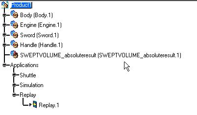
305 Page 305


306 Page 306 Filtering Swept Volume Positions This task shows how to filter swept volume positions which provides a performance gain. Open the Product1duo2.CATProduct document. You recorded a multi-shuttle simulation and compiled it. You obtained a Replay object. You need to perform clash analysis between two items. You generated a simple swept volume but you are not satisfied with the swept volume result. You need a coarser result. 1. Select ReplayForFilter in the specification tree. 2. Click the Swept Volume icon. The Swept Volume dialog box is displayed.

307 Page Click in the product(s) to sweep spin box, the Product Multi-selection dialog box lets you select or deselect the products you want to sweep. 4. Multi-select shuttle 2 and GARDENA_NOZZLE_1_ Click Ok to confirm your operation 6. Keep the Filter Positions option set. 7. Enter 20mm as filtering precision value.

308 Page 308 Click Preview The preview window shows the result: 8. Click Save in the Swept Volume dialog box. The Save As dialog box automatically appears.

309 Page Select cgr file from the Save as type drop-down list. When done, click Save Note you can now save your swept volume result as a STL model file 10. Click Close when satisfied. Now, import the swept volume result into your product 11. Right-click Product.1 in the specification tree. 12. Select Components-> Existing component from the contextual menu displayed. Select GARDENA,NOZZLE_1_2.1_SWEPTVOLUME.cgr from the samples folder. This is what you obtain: The Swept volume result is identified in the specification tree.
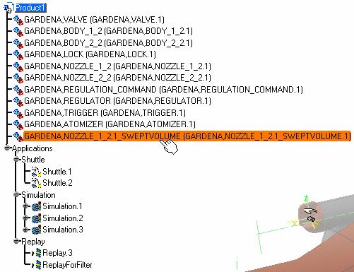
310 Page 310
311 Defining a Swept Volume from any Moving Reference Page 311 This task shows how to define a swept volume from a moving reference. In other words: the swept volume of a moving part in the axis system of anther moving part. It can be very useful if you need to perform clash detection or if you need to calculate the minimum distance between two products moving within the same replay object. Open the FIT_SWEPT_VOL.CATProduct document. You recorded a multi-shuttle simulation and compiled it. You obtained a Replay object. Please refer to Generating a Replay. You need to perform clash analysis between two items. You generated a simple swept volume. Please refer to Defining a Swept Volume. You are not satisfied with the swept volume result as the clash detection is not clear enough. You need to generate another swept volume using the DEMO_CGE_CHAINSAW_ENGINE_CLUTCHDRUM.1 as reference product. 1. Click the Swept Volume icon. The Swept Volume dialog box is displayed. 2. Select DEMO_CGE_CHAINSAW_ENGINE_CLUTCHHUB.1 as product to sweep. 3. In the Reference product field, click to display the Reference Product Selection dialog box: 4. Select DEMO_CGE_CHAINSAW_ENGINE_CLUTCHDRUM.1 as reference product. 5. Click Ok to confirm your operation. The Swept Volume dialog box is automatically updated.


312 Page Click Apply to generate the swept volume. The progress bar is displayed letting you monitor and, if necessary, interrupt (Cancel option) the calculation. The preview window shows the result: 7. Click OK. The Save As dialog box appears:


313 Page Select cgr file from the Save as type drop-down list. When done, click Save. Note you can now save your swept volume result as a STL model file Now, import the swept volume result into your product. 9. Right-click DEMO_CGE_CHAINSAW_ENGINE_CLUTCHDRUM.1 in the specification tree 10. Select Components->Existing Component from the contextual menu and select SWEPTVOLUME_relativeresult.cgr from the samples folder. This is what you obtain: The Swept volume result is identified in the specification tree
314 Page 314

315 Page 315 More About Swept Volume About Filter positions option: This option can be used to simplify the swept volume computation when the replay object contains many positions or when you know what precision level you need to obtain. The "filter precision" defines the maximum distance allowed between the simplified trajectory and the initial one (= discretization precision) 1- Filtering swept volume positions The following example aims at illustrating the impact of the filter positions option on the final result Case 1: the Filter positions option is not checked:


316 Page 316 Case 2: the Filter positions option is checked Filtering precision = 5mm

317 Page 317 Case 3: the Filter positions option is checked Filtering precision = 10mm 2- Relative swept volume
 Example: two moving parts: circle and square With the basic computation of the")
318 Page 318 About Relative swept volume: You can compute the swept volume of a moving part in the system axis of another moving part. You can use this option when you need to analyze the swept volume of a product versus another product (moving or not) Example: two moving parts: circle and square With the basic computation of the swept volumes, the clash analysis is not relevant: the swept volumes clash but two objects may not be in the same clash area at the same time.

319 Page 319 If you use the relative swept volume option and select the circle as the reference product, you can compute the square swept volume in the circle system axis. The result can now be relevant for clash analysis.
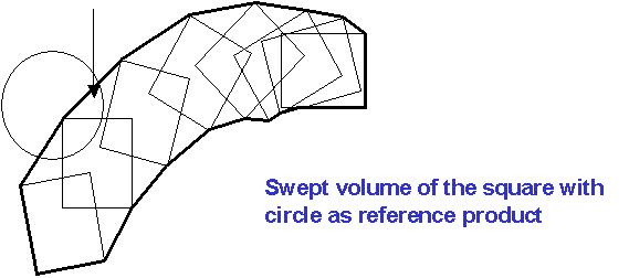
320 Page 320
321 Page 321 Interoperability This section provides information on how to use the DMU Fitting product with other Dassault products. Interoperability With Catia V4 How to do a Safe Save in ENOVIA LCA from CATIA V5
322 Page 322 Interoperability With CATIA V4 Write Axis Systems From a V5 track to a V4 Model Licensing The following capabilities are available only with a V4I license. Read a V4 route (track + shuttle) in a V5 Session

323 Page 323 Writing Axis Systems from a V5 Track to a V4 Model This task shows how to export a V5 track definition in V4. Each V5 recorded position is exported as an Axis in one V4 model document. It is then possible to rebuild a V4 track from these positions. This functionality is very useful when you are designing products in CATIA V4 and reviewing your DMU in Fitting V5. You can easily retrieve information from your V5 review to perform modifications in CATIA V4. Note: The user needs to rebuild a route in V4 from the exported axis systems. Open the EXPORT_V5_TRACK.CATProduct document. 1. Double-click Track.2 in the specification tree. 2. Click the arrow within the Clash Detection icon Undock the toolbar if necessary. from the DMU Check toolbar. 3. Set the Clash detection to on 4. Play your track simulation using the Player 5. There is a collision detected at recorded position 3. You need to modify your design.

324 Page Select the track.2 either in the geometry area or in the specification tree. 7. Select Tools->Simulation->Track File Export The Track File Export dialog box automatically appears: 8. Enter a meaningful name and select.model format from the Save as Type drop-down list:
325 Page Open the EXPORT_V5_TRACK.model document you have just created (from cfyug/samples) This is what you obtain: Note: Double-click Master node to display the specification tree
326 Page In this V4 model document we selected axis system 3 (highlighted) which corresponds in the dismounting review to the position 3 where a collision was detected. You are now ready to modify your design using this information. Remember though: There are not any V4 Fitting entities created. V4 tracks do not exactly share the same behaviors with V5 tracks (such as interpolation, etc.)
327 Page 327 Reading V4 Routes and Sequences in a V5 Session This task shows how to read a V4 route (track +shuttle) as well as a sequence in DMU Fitting V5. When inserting a V4 model in V5 product, if the model contains V4 routes and shuttles, the routes and shuttles will be read. Similarly, sequences will also be read. They will be selectable in the navigation tree under the *MASTER container. A copy/paste operation from the V4 Master container to the V5 Tracks container will convert the V4 Routes into V5 tracks. Similarly, sequences will convert to V5 sequences. A V4 Route is the association of: 1 Shuttle, 1 Home position and n Trajectories. A V5 Track is the association of: 1 Shuttle or 1 Product, and 1 Trajectory. The conversion will concatenate the positions in the V4 Home and Trajectories to generate a single V5 path. Insert the following.model files in the samples folder: FITTING_DATA.model FUEL_TUBE.model NAVIGATION_BOX.model OVERALL_STRUCTURE.model SUPPORT_BEAM.model 1. In the specification tree where the Version 4 model is displayed, select the item you wish to copy into the Fitting Simulator Version 5. In our example, expand FITTING_DATA and *MASTER items and multi-select. 3-TUBE REMOVAL 2-BOX REMOVAL 1-BEAM REMOVAL

328 Page Put the data you have selected in the clipboard. To do this, either click the Copy icon, select the Edit->Copy command or select the Copy command in the contextual menu. To obtain the sequences, copy the items under the SEQS1 node.


329 Page Select Application in the specification tree. 4. Now either click the Paste icon, select the Edit->Paste command or select the Paste command in the contextual menu. This operation recovers the data previously put in the clipboard The result appears as shown below:


330 Page Open the READ_V4_ROUTE.CATProduct to check your result 6. For instance, select 1- BEAM REMOVAL in the specification tree and click the Player icon. Simulate the track using the DMU player buttons: Note: the V4 model referenced by the V4 shuttle must not be renamed. Otherwise, it may create broken links, which would disable the V4/V5 conversion.
331 Page 331 How to do a Safe Save into ENOVIA LCA from CATIA V5 The objective of Safe Save is to prevent the user from building / editing data in CATIA V5 if they cannot be saved in ENOVIA LCA. Therefore, in interoperability mode, some CATIA V5 commands are grayed out / hidden in the DMU Fitting Simulator workbench. Only commands subject to restrictions are listed below. And in some cases, rules are applied to restricted commands. Workbench Feature Command Accessibility in LCA mode Warning / Comment Save in LCA / Rules Track NO (grayed out) Color Action NO (grayed out) Edit Sequence NO (grayed out) DMU Simulation Edit and Perform Experiment Simulation Player Swept Volume NO (grayed out) NO (grayed out) NO (grayed out) D M U F I T T I N Explode Shuttle Reset position Path finder Smooth NO (grayed out) NO (grayed out) YES YES YES
332 Page 332 G DMU Check Clash YES Clash results cannot be saved unless the Retrieve Information from PDM option is set in the DMU Clash tab page (Tools - > Options - > Digital Mockup -> DMU Space Analysis). See DMU Space Analysis User's Guide for more information. A warning dialog box displays. G E N E R I C C O M M A N D S Generic commands (Generic tools) Distance and Band Analysis Clash Detection Publish YES YES YES Camera YES Distance data is not saved; there is a warning displayed.


333 Workbench Description Page 333 This section contains the description of the icons and menus which are specific to the DMU Fitting Simulator workbench. The DMU Fitting Simulator window is shown below. Click the sensitive areas (toolbars) to see the related documentation. Menu Bar Simulation Toolbar DMU Check Toolbar Manipulation Toolbar Automatic Clash Detection Toolbar Specification Tree Recorder Player

334 DMU Fitting Simulator Menu Bar Page 334 Here we will present the various menus and menu commands that are specific to DMU Fitting Simulator version 5. Start File Edit View Insert Tools Analyze Window Help Insert For... See... Sequences & actions Measuring Distances track Detecting Interferences color Action Visibility Action Defining/Editing Several Shuttles Edit Sequence Moving and Recording a Multi-Shuttle Simulation Shuttle Simulation Clash Distance and band Analysis Group Entering in the DMU Navigator and Selecting Models Tools For... See... Convert Simulation Generate Video Generate Replay Measuring Distances Using DMU Video Generation Tool Detecting Interferences Replay Defining/Editing Several Shuttles Player DMU Player


335 Track file export Exporting and Importing Tracks in Neutral Format Page 335 Writing Axis Systems From a V5 track to a V4 Model Track file import Exporting and Importing Tracks in Neutral Format Window For... See... new Gantt Chart Window Displaying Gantt Chart Camera Window See Using Camera Capabilities in DMU Navigator User's Guide Tasks corresponding to the general menu commands are described in the Infrastructure User's Guide.
336 Page 336 DMU Simulation Toolbar The DMU Simulation toolbar contains a number of tools that are useful for DMU Fitting Simulator. Other Actions toolbar: is displayed when you click the arrow within the Color action icon and undock it See: Tracks See: Defining Sequences See: About Sequence Capabilities See: Sequences See About Sequence Capabilities See: Sequence Editor See: Defining a Sequence See: Performing Experiments and Generating Simulation Reports See DMU Player See Defining a Swept Volume See Defining a Swept volume from a Moving Reference See Exploding See Shuttle See: Exploding a Constrained Assembly See: Copying and Pasting Tracks
337 Page 337
338 Page 338 DMU Check Toolbar Licensing The following functionalities: "Clash" and "Distance and Band Analysis" are available only with a DMU Space Analysis license. See Path finder See Using the Smooth Command See Detecting Interferences See Measuring Distances See Detecting Clashes Automatically
339 Page 339 Manipulation Toolbar The Manipulation toolbar contains a number of tools that are useful for DMU Fitting Simulator. It displays when using the Shuttle, Explode, Track and Simulation commands (if based on one or various shuttle(s). Track-based manipulation toolbar Shuttle-based manipulation toolbar For more detailed information about these commands, please refer to: More About Manipulation Toolbar See Using the Smart Target See Using the Smart Snap See Target and Snap Capabilities See Moving the Shuttle See Moving the Shuttle See Snapping Objects in Approach Phase See Editing a Shuttle See Moving the Shuttle See Moving the Shuttle
340 Page 340 Automatic Clash Detection Toolbar See Validating Positions Automatically

341 Page 341 Specification Tree Within the DMU Fitting Simulator workbench, you can generate a number of features that are identified in the specification tree by the following icons:
342 Page 342 Icons displayed in the specification tree and specific to the DMU Fitting Simulator workbench identify: Color actions Tracks Sequences Visibility actions Experiments Shuttles Simulations Replays Groups Clash entries Distance and band analysis entries Measures made using the Measure Item command Measures made using the Measure Between command For standard specification tree symbols, see the Infrastructure User's Guide.
343 Page 343 Recorder Toolbar See: Track Editor and Recorder See: Recording a Track See: Track Editor and Recorder See: Track Editor and Recorder
344 Page 344 Player See Player
345 Page 345 Customizing for DMU Fitting Simulator Customizing DMU Fitting Settings Customizing DMU Manipulation Settings Customizing DMU Navigator Settings

346 Page 346 Customizing DMU Fitting Settings This task explains how to customize DMU Fitting settings. 1. Select Tools -> Options from the menu bar: The Options dialog box appears. 2. Click Digital Mockup in the left-hand frame, then DMU Fitting. The DMU Fitting tab is active by default. If it is not on top, select it. The default values are shown below. Shuttle Angular Validation Checking the box enables you set the angular shuttle validation option in the Edit Shuttle dialog box. You can specify a maximum rotation angle for the shuttle and the vector around which the shuttle will rotate.
347 Page 347 Path Finder Automatic Smooth: If checked, smooth is performed within the pathfinder command once you click the OK button. Track Automatic track update: if checked, the track is automatically updated after modification. The manual update is set by default (see the track contextual menu). Default speed is 0.001m_s. You can modify this value at any time. When you modify the default speed, the modification applies to tracks created after the modification. To modify the speed on existing tracks, use the Properties dialog box. Default Clash Detection When activating the default clash detection, the clash computation can take several minutes before the simulation dialog boxes are displayed. Sometimes it is more convenient not to compute this clash detection for the first step. This step can already be validated by a static clash analysis. Activated only while moving: if checked, no calculation will be performed when the default clash detection is activated (ON, STOP). When running tracks, sequencesm, and simulations, clashes are still calculated with respect to the default clash detection state (OFF, ON, STOP) By default this option is not checked 3. Click OK in the dialog box when done. [ Up ] [ Next ]

348 Customizing DMU Manipulation Settings Page 348 This task explains how to customize DMU Fitting settings. 1. Select Tools -> Options from the menu bar: The Options dialog box appears. 2. Click Digital Mockup in the left-hand frame, then DMU Fitting. 3. Select the DMU Manipulation tab. The default values are shown below. Clash Feedback Click the Clash Beep checkbox to activate the Beep during interference analyses, simulation recordings, etc. By default, the Clash Beep option is unchecked. Automatic Insert Configurations

349 Page 349 On mouse release (default): Lets you record positions on mouse release. While mouse moving: Distance: Specifies the minimum distance step during simulation recording. Angle: Specifies the maximum rotation angle step during simulation recording. The Distance and Angle fields are only grayed out when On mouse release is checked. Once While mouse moving is checked, you can enter the appropriate values to record the the motion. Regardless of which configuration you have selected, you will not get Automatic Insert unless the Automatic Insert option is checked in Manipulation Mode, described in the section below. Manipulation Mode for Simulations and Tracks Lets you validate the shuttle simulation detecting clashes. This setting is linked to the Automatic Clash Detection toolbar. The icon changes automatically with respect to the option checked. No clash detection (default) : Clash detection will not occur. Clash detection on : Activates the clash detection mode (The objects in clash are highlighted in the geometry area while recording the simulation ) Stop on collision : Activates the stop mode. Consequently, the simulation stops once any objects clash. The objects in clash are highlighted in the geometry area. Automatic insert: When checked, it enables automatic insert mode. Automatic insert mode enable users to insert shots in a track without using the Record (Insert) command on the Recorder toolbar. The two configurations available for Automatic Insert appear above. Snap Sensitivity Lets you customize the snap functionality parameters within a sphere and a cylinder: Position value: Specifies the sphere radius (first area) where the shuttle is snapped onto the object. Orientation value: Specifies the cylinder height (second area) where the shuttle is snapped onto the object. 3. Click OK in the dialog box when done. [ Back ] [ Up ]

350 Page 350 Customizing DMU Navigator Settings This task explains how to customize DMU Navigator settings. 1. In the menu bar, select Tools -> Options. The Options dialog box appears. 2. Click the Digital Mockup category, then click the DMU Navigator tab.

351 Page 351 The DMU Navigator tab enables you to customize: Hyperlink representation (name) Marker Default Properties Scene Default Properties 3D annotation update (when moving the product) Spatial Query parameters Import of applicative data You can add hyperlinks to your document and then use them to jump to a variety of locations, for example, to a marketing presentation, a Microsoft Excel spreadsheet or a HTML page on the intranet. 3. In the Hyperlink Representation area, check the Name selection box. By default, hyperlink names are displayed : all hyperlink will be textual. The name you give the link in the Manage Hyperlink dialog box when you create it will appear when using go to hyperlink. 4. Click preview checkboxes as appropriate to change the automatic display setting of preview windows when creating cameras, manipulating objects, etc. By default, preview windows are automatically displayed.
DMU Engineering Analysis Review
 DMU Engineering Analysis Review Overview Conventions What's New? Getting Started Entering DMU Engineering Analysis Review Workbench Generating an Image Visualizing Extrema Generating a Basic Analysis Report
DMU Space Analysis Version 5 Release 13. DMU Space Analysis
 Page 1 DMU Space Analysis Preface Using This Guide More Information Conventions What's New? Getting Started Setting Up Your Session Measuring Minimum Distances Sectioning Detecting Clashes Measuring Between
DMU Engineering Analysis Review
 Page 1 DMU Engineering Analysis Review Preface Using This Guide Where to Find More Information Conventions What's New? Getting Started Inserting a CATAnalysis Document Using DMU Space Analysis From CATAnalysis
DMU Space Engineering Assistant User Guide
 Page 1 DMU Space Engineering Assistant User Guide Overview Conventions What's New? Getting Started User Tasks Setting Up Your Session Running a Interference Workbench Description DMU Space Engineering
DMU Space Engineering Assistant User Guide
 DMU Space Engineering Assistant User Guide Overview Conventions What's New? Getting Started User Tasks Setting Up Your Session Running an Interference Analysis Workbench Description DMU Space Engineering
Fastening Review Overview Basic Tasks DMU Fastening Review Interoperability Workbench Description Customizing Index
 Fastening Review Overview Conventions Basic Tasks Displaying Joined Parts in a Balloon Running the Fastening Rules Analysis Reporting Creating Structural Reports Creating Flat Reports DMU Fastening Review
Electrical 3D Design & Documentation
 Electrical 3D Design & Documentation Page 1 Overview Conventions User Tasks Using Electrical 3D Design & Documentation Entering the Electrical Assembly Design Workbench Entering the Electrical Part Design
DMU Optimizer Overview What's New? Getting Started User Tasks
 DMU Optimizer Overview Conventions What's New? Getting Started Starting a Session Generating a Silhouette Generating a Wrapping Generating a Thickness Generating an Offset Generating a Free Space User
Equipment Support Structures
 Page 1 Equipment Support Structures Preface Using This Guide Where to Find More Information Conventions What's New? Getting Started Setting Up Your Session Creating a Simple Structural Frame Creating Non-uniform
Electrical System Functional Definition
 Electrical System Functional Definition Preface What's New? Getting Started Basic Tasks Advanced Tasks Workbench Description Customizing Glossary Index Dassault Systèmes 1994-2000. All rights reserved.
Equipment Support Structures
 Equipment Support Structures Overview Conventions What's New? Getting Started Setting Up Your Session Creating a Simple Structural Frame Creating Non-uniform Columns Creating Plates with Openings Bracing
NC Manufacturing Verification
 NC Manufacturing Verification Page 1 Preface Using This Guide Where to Find More Information Conventions What's New? User Tasks Accessing NC Manufacturing Verification Comparing the Machined Stock Part
NC Manufacturing Verification
 NC Manufacturing Verification Overview Conventions What's New? User Tasks Accessing NC Manufacturing Verification Comparing the Machined Stock Part and the Design Part Pick Point Analysis in Video Mode
Electrical System Functional Definition
 Electrical System Functional Definition Overview Conventions What's New? Getting Started Creating a New System Creating Equipment Creating Connectors Creating a Signal Connecting Saving Your System User
Electrical Harness Installation
 Electrical Harness Installation Page 1 Overview Conventions What's New? Getting Started Entering the Workbench Setting Up the Options Creating a Bundle Segment Document Creating Construction Points Defining
Product Structure Version 5 Release 13. Product Structure
 Product Structure Page 1 Site Map Preface Conventions What's New? Basic Tasks Entering the Product Structure Workbench Opening a CATProduct with a Progress Bar Selecting Products only Selecting Modes Inserting
Advanced Meshing Tools
 Page 1 Advanced Meshing Tools Preface Using This Guide More Information Conventions What's New? Getting Started Entering the Advanced Meshing Tools Workbench Defining the Surface Mesh Parameters Setting
Tolerance Analysis of Deformable Assembly
 Tolerance Analysis of Deformable Assembly Overview Conventions What's New? Getting Started Entering the Workbench Creating a New Analysis Importing the Assembly Definition Computing a Tolerance Analysis
Circuit Board Design Version 5 Release 13. Circuit Board Design
 Circuit Board Design Page 1 Overview Conventions What's New? Getting Started Accessing the Circuit Board Workbench Creating a Board Pocket and Holes Constraint Area Exporting Data Importing Data User Tasks
Prismatic Machining Overview What's New Getting Started User Tasks
 Prismatic Machining Overview Conventions What's New Getting Started Enter the Workbench Create a Pocketing Operation Replay the Toolpath Create a Profile Contouring Operation Create a Drilling Operation
Electrical Wire Routing
 Electrical Wire Routing Page 1 Overview Conventions What's New? Getting Started Accessing the Workbench Creating the Bundle Selecting Systems with External Data Routing Wires from External Data User Tasks
Electrical Harness Flattening
 Electrical Harness Flattening Overview Conventions What's New? Getting Started Accessing the Electrical Harness Flattening Workbench Defining the Harness Flattening Parameters Extracting Data Flattening
Human Posture Analysis
 Human Posture Analysis Overview Conventions What's New? Getting Started Creating a Manikin User Tasks Using the Posture Editor Selecting or Editing the DOF (Degree of Freedom) Displaying and Editing Angular
Human Posture Analysis
 Human Posture Analysis Page 1 Preface Using This Guide Where to Find More Information Conventions What's New? Getting Started Creating a Manikin User Tasks Using the Posture Editor Segments Degree of Freedom
Electrical Library Version 5 Release 13. Electrical Library
 Electrical Library Page 1 Overview Conventions What's New? Getting Started Entering the Electrical Part Design Workbench Defining a Single Insert Connector Defining a Cavity Connection Point Entering Electrical
Photo Studio. Preface What`s New? Getting Started Basic Tasks Advanced Tasks Workbench Description Customizing Glossary Index
 Photo Studio Preface What`s New? Getting Started Basic Tasks Advanced Tasks Workbench Description Customizing Glossary Index Dassault Systèmes 1994-2000. All rights reserved. Preface Welcome to Version
Structure Preliminary Layout
 Page 1 Structure Preliminary Layout Preface Using This Guide Where to Find More Information What's New? Getting Started Setting Up Your Session Defining the Hull Form Setting Up Your Grid Creating Molded
Piping Design. Site Map Preface Getting Started Basic Tasks Advanced Tasks Customizing Workbench Description Index
 Piping Design Site Map Preface Getting Started Basic Tasks Advanced Tasks Customizing Workbench Description Index Dassault Systèmes 1994-2001. All rights reserved. Site Map Piping Design member member
DMU Fitting Simulate part motions for assembly and maintainability issues
 DMU Fitting Simulate part motions for assembly and maintainability issues Toolbars A B A. DMU Simulation: Key tools for DMU Fitting B. DMU Check: Measure Interference, distance, detect Clash while moving
HVAC Diagrams Preface What's New? Getting Started User Tasks
 HVAC Diagrams Preface Using This Guide What's New? Getting Started Entering the Workbench Setting up Working Units and Grid Placing Components Routing an HVAC Line Placing Components in a Line Repositioning
Using Smart Search. Understanding Smart Search CHAPTER
 CHAPTER 9 Cisco Smart Search analyzes archived, live, or saved video clips and detects and indexes points at which motion events occurs. Operators can then easily review these motion events by using the
Structure Preliminary Layout
 Structure Preliminary Layout Overview Conventions What's New? Getting Started Setting Up Your Session Defining the Hull Form Setting Up Your Grid Creating Molded Forms Creating a Compartment Creating Boundaries
Piping & Instrumentation Diagrams
 Piping & Instrumentation Diagrams Preface Using This Guide What's New? Getting Started Entering the Workbench Setting up Working Units and Grid Placing Components Routing a Piping Line or I & C Loop Placing
FreeStyle Shaper & Optimizer
 FreeStyle Shaper & Optimizer Preface What's New Getting Started Basic Tasks Advanced Tasks Workbench Description Customizing Glossary Index Dassault Systèmes 1994-99. All rights reserved. Preface CATIA
Getting Started with ShowcaseChapter1:
 Chapter 1 Getting Started with ShowcaseChapter1: In this chapter, you learn the purpose of Autodesk Showcase, about its interface, and how to import geometry and adjust imported geometry. Objectives After
Knowledge Expert Overview What's New? Getting Started Basic Tasks Advanced Tasks Reference
 Knowledge Expert Overview Conventions What's New? Getting Started Creating an Expert Check Creating an Expert Rule Basic Tasks About RuleBases Storing a Rule Base in a Catalog Using a Rule Base Stored
Piping & Instrumentation Diagrams
 Page 1 Piping & Instrumentation Diagrams Preface Using This Guide What's New? Getting Started Entering the Workbench Setting up Working Units and Grid Placing Components Routing a Piping Line or I & C
Systems Space Reservation
 Systems Space Reservation Preface Using This Guide What's New? Getting Started Enter the Workbench Create an Equipment Reservation Set Correct Working Units and Grid Changing the Current Axis Saving Documents
Photo Studio Version 5 Release 13. Photo Studio
 Photo Studio Page 1 Preface Using This Guide More Information Conventions What's New? Getting Started Entering the Photo Studio Workbench Loading Products Creating a Quick Render Basic Tasks Camera Management
All textures produced with Texture Maker. Not Applicable. Beginner.
 Tutorial for Texture Maker 2.8 or above. Note:- Texture Maker is a texture creation tool by Tobias Reichert. For further product information please visit the official site at http://www.texturemaker.com
FreeStyle Shaper Optimizer & Profiler
 FreeStyle Shaper Optimizer & Profiler Page 1 Preface Using This Guide More Information What's New? Getting Started Starting the FreeStyle Workbench Creating a First Surface Editing the Surface Creating
GraphWorX64 Productivity Tips
 Description: Overview of the most important productivity tools in GraphWorX64 General Requirement: Basic knowledge of GraphWorX64. Introduction GraphWorX64 has a very powerful development environment in
Aerospace Sheetmetal Design
 Aerospace Sheetmetal Design Page 1 Overview Conventions What's New? Getting Started Entering the Aerospace SheetMetal Design Workbench Defining the Aerospace SheetMetal Parameters Creating a Web from a
USING THE TRIBALL FOR POSITIONING
 USING THE TRIBALL FOR POSITIONING Although many important positioning tools are available, none are as versatile as the TriBall tool. This TriBall tool offers complete repositioning of many items: Shapes
How to add video effects
 How to add video effects You can use effects to add a creative flair to your movie or to fix exposure or color problems, edit sound, or manipulate images. Adobe Premiere Elements comes with preset effects
Preface. Version 5 Release 5. Mold Tooling Design
 Version 5 Release 5 Mold Tooling Design Preface Getting Started Basic Tasks Advanced Tasks Customization Workbench Description Glossary Index Preface The CATIA Version 5 Mold Tooling Design application
2 The Stata user interface
 2 The Stata user interface The windows This chapter introduces the core of Stata s interface: its main windows, its toolbar, its menus, and its dialogs. The five main windows are the Review, Results, Command,
Introduction And Overview ANSYS, Inc. All rights reserved. 1 ANSYS, Inc. Proprietary
 Introduction And Overview 2006 ANSYS, Inc. All rights reserved. 1 ANSYS, Inc. Proprietary The ANSYS Workbench represents more than a general purpose engineering tool. It provides a highly integrated engineering
Compartment and Access
 Compartment and Access Page 1 Preface Using This Guide What's New? Getting Started Entering the Workbench Set Correct Working Units and Grid Saving Documents User Tasks Creating/Modifying Wall Systems
Adjust model for 3D Printing. Positioning - Orientate the part 13,0600,1489,1604(SP6)
") Adjust model for 3D Printing 13,0600,1489,1604(SP6) In this document, we will learn about. Position and Orientate a Body means that we move and rotate the body to fit our 3D printing considerations. Typical
Adjust model for 3D Printing 13,0600,1489,1604(SP6) In this document, we will learn about. Position and Orientate a Body means that we move and rotate the body to fit our 3D printing considerations. Typical
SolidWorks Intro Part 1b
 SolidWorks Intro Part 1b Dave Touretzky and Susan Finger 1. Create a new part We ll create a CAD model of the 2 ½ D key fob below to make on the laser cutter. Select File New Templates IPSpart If the SolidWorks
Podium Plus Data Analysis Software. User Manual. SWIS10 Version
 SWIS10 Version Issue 1.10 February 2005 Contents 1 Introduction 6 1.1 What is Podium Plus? 6 1.2 About This Manual 6 1.3 Typographical Conventions 7 1.4 Getting Technical Support 7 2 Getting Started 8
Autodesk Fusion 360 Training: The Future of Making Things Attendee Guide
 Autodesk Fusion 360 Training: The Future of Making Things Attendee Guide Abstract After completing this workshop, you will have a basic understanding of editing 3D models using Autodesk Fusion 360 TM to
Knowledge Advisor Overview What's New? Getting Started User Tasks
 Knowledge Advisor Overview Conventions What's New? Getting Started Using Parameters Using Formulas Using Rules Using Checks User Tasks Working with Parameters Creating a Parameter Introducing Parameters
Chapter 9 Slide Shows
 Impress Guide Chapter 9 Slide Shows Transitions, animations, and more Copyright This document is Copyright 2007 2011 by its contributors as listed below. You may distribute it and/or modify it under the
Autodesk Navisworks Freedom Quick Reference Guide
 WP CAD 00074 March 2012 Guide by Andy Davis Autodesk Navisworks Freedom Quick Reference Guide Quick Reference Guide to Autodesk Navisworks Freedom Opening a Model To open a model, click on the Application
SolidWorks Implementation Guides. User Interface
 SolidWorks Implementation Guides User Interface Since most 2D CAD and SolidWorks are applications in the Microsoft Windows environment, tool buttons, toolbars, and the general appearance of the windows
2 Getting Started. Getting Started (v1.8.6) 3/5/2007
 3/5/2007") 2 Getting Started Java will be used in the examples in this section; however, the information applies to all supported languages for which you have installed a compiler (e.g., Ada, C, C++, Java) unless
2 Getting Started Java will be used in the examples in this section; however, the information applies to all supported languages for which you have installed a compiler (e.g., Ada, C, C++, Java) unless
Human Builder. Preface Using this Guide Where to Find More Information Conventions. What's New?
 Human Builder Page 1 Preface Using this Guide Where to Find More Information Conventions What's New? Getting Started Standard Manikin Creation Creating a Forearm/Hand Model Changing Manikin Display Attributes
Shape Sculptor Version 5 Release 13. Shape Sculptor
 Shape Sculptor Page 1 Overview Using This Guide Where to Find More Information What's New? Getting Started Entering the Workbench Importing a Polygonal Mesh Decimating a Polygonal Mesh User Tasks Input
Visual Physics - Introductory Lab Lab 0
 Your Introductory Lab will guide you through the steps necessary to utilize state-of-the-art technology to acquire and graph data of mechanics experiments. Throughout Visual Physics, you will be using
Lectora Audio Editor Information Center
 Lectora Audio Editor Information Center - 1 - Welcome to the Lectora Audio Editor Information Center The Audio Editor Information Center was designed so that you can quickly find the information you need
Using the VSOM Operator Pages
 CHAPTER 8 The VSOM Operator Pages provide access to features that video surveillance operators can use to view, record, search, and control video. This chapter describes the Operator Pages in detail. It
To familiarize of 3ds Max user interface and adapt a workflow based on preferences of navigating Autodesk 3D Max.
 Job No: 01 Duration: 8H Job Title: User interface overview Objective: To familiarize of 3ds Max user interface and adapt a workflow based on preferences of navigating Autodesk 3D Max. Students should be
SOLIDWORKS: Lesson 1 - Basics and Modeling. Introduction to Robotics
 SOLIDWORKS: Lesson 1 - Basics and Modeling Fundamentals Introduction to Robotics SolidWorks SolidWorks is a 3D solid modeling package which allows users to develop full solid models in a simulated environment
LAB # 2 3D Modeling, Properties Commands & Attributes
 COMSATS Institute of Information Technology Electrical Engineering Department (Islamabad Campus) LAB # 2 3D Modeling, Properties Commands & Attributes Designed by Syed Muzahir Abbas 1 1. Overview of the
SolidWorks 2½D Parts
 SolidWorks 2½D Parts IDeATe Laser Micro Part 1b Dave Touretzky and Susan Finger 1. Create a new part In this lab, you ll create a CAD model of the 2 ½ D key fob below to make on the laser cutter. Select
Animation Basics. Learning Objectives
 Animation Basics Learning Objectives After completing this chapter, you will be able to: Work with the time slider Understand animation playback controls Understand animation and time controls Morph compound
Alternate assemblies
 Alternate assemblies Publication Number spse01685 Alternate assemblies Publication Number spse01685 Proprietary and restricted rights notice This software and related documentation are proprietary to
전산응용설계 (Computer Aided Design)
") 전산응용설계 (Computer Aided Design) CATIA (Computer Aided Three dimensional Interactive Application) 기계자동차공학부자동차공학전공 Chapter 3. CATIA 기초 학습내용 : 객체선택 (Selecting Objects) 객체감추기와보이기 (Hiding and Showing objects)
전산응용설계 (Computer Aided Design) CATIA (Computer Aided Three dimensional Interactive Application) 기계자동차공학부자동차공학전공 Chapter 3. CATIA 기초 학습내용 : 객체선택 (Selecting Objects) 객체감추기와보이기 (Hiding and Showing objects)
Using Open Workbench Version 1.1
 Version 1.1 Second Edition Title and Publication Number Title: Edition: Second Edition Printed: May 4, 2005 Copyright Copyright 1998-2005 Niku Corporation and third parties. All rights reserved. Trademarks
Chapter 9 Slide Shows
 Impress Guide Chapter 9 Slide Shows Transitions, animations, and more Copyright This document is Copyright 2007 2012 by its contributors as listed below. You may distribute it and/or modify it under the
Step 1: Open the CAD model
 In this exercise you will learn how to: Ground a part Create rigid groups Add joints and an angle motor Add joints and an angle motor Run both transient and statics motion analyses Apply shape controls
Solidworks 2006 Surface-modeling
 Solidworks 2006 Surface-modeling (Tutorial 2-Mouse) Surface-modeling Solid-modeling A- 1 Assembly Design Design with a Master Model Surface-modeling Tutorial 2A Import 2D outline drawing into Solidworks2006
Tetra4D Reviewer. Version 2018 User Guide. Document version: V3.0. Tetra4D Reviewer 2018 Users Guide V3.0 1
 Tetra4D Reviewer Version 2018 User Guide Document version: V3.0 Tetra4D Reviewer 2018 Users Guide V3.0 1 Table of Contents Chapter 1: Tetra4D Reviewer overview... 4 Tetra4D Reviewer application... 4 Tetra4D
Creating Interactive Procedures and Training Courses
 Creating Interactive s and Training Courses 2017 ParallelGraphics CONTENTS INTRODUCTION... 1 1 PROCESS LAYOUT AND BASIC OPERATIONS... 1 1.1 General Data Flow Diagram... 2 1.2 Preparing Input Data for RapidAuthor
PediGait IP. Users Manual
 PediGait IP Users Manual April 2012 Table of Contents Clients Tab... 2 Open a Client file... 2 Delete Client file(s)... 2 Edit a Client... 3 Add a new client... 3 Add Comments to client files... 4 Profiles
Gamepad Controls. Figure 1: A diagram of an Xbox controller. Figure 2: A screenshot of the BodyViz Controller Panel. BodyViz 3 User Manual 1
 BodyViz User Manual Gamepad Controls The first step in becoming an expert BodyViz user is to get acquainted with the Xbox gamepad, also known as a controller, and the BodyViz Controller Panel. These can
button in the lower-left corner of the panel if you have further questions throughout this tutorial.
 Mosaic Tutorial: Simple Workflow This tutorial demonstrates how to use the Seamless Mosaic tool to mosaic six overlapping digital aerial scenes. You will learn about displaying footprints and image data
Compartment and Access
 Compartment and Access Preface Using This Guide What's New? Getting Started Entering the Workbench Set Correct Working Units and Grid Saving Documents User Tasks Creating/Modifying Wall Systems Building
Numbers Basics Website:
 Website: http://etc.usf.edu/te/ Numbers is Apple's new spreadsheet application. It is installed as part of the iwork suite, which also includes the word processing program Pages and the presentation program
Introduction to IBM Rational HATS For IBM System i (5250)
") Introduction to IBM Rational HATS For IBM System i (5250) Introduction to IBM Rational HATS 1 Lab instructions This lab teaches you how to use IBM Rational HATS to create a Web application capable of transforming
Introduction to IBM Rational HATS For IBM System i (5250) Introduction to IBM Rational HATS 1 Lab instructions This lab teaches you how to use IBM Rational HATS to create a Web application capable of transforming
Tetra4D Reviewer. Version 5.1. User Guide. Details on how to use Tetra4D Reviewer.
 Tetra4D Reviewer Version 5.1 User Guide Details on how to use Tetra4D Reviewer. ii Contents Chapter 1: Work area... 7 Looking at the work area... 7 Toolbars and toolbar presets... 8 About toolbars and
Keynote 08 Basics Website:
 Website: http://etc.usf.edu/te/ Keynote is Apple's presentation application. Keynote is installed as part of the iwork suite, which also includes the word processing program Pages and the spreadsheet program
1 Interface Fundamentals
 1 Interface Fundamentals Windows The Media Composer interface is focused on three primary windows: the Composer, the Timeline and the Project. The Composer window contains the source and record monitors
WATERMARK S ENSE User Guide. VeprIT.
 WATERMARK S ENSE User Guide VeprIT http://veprit.com support@veprit.com Based on version 1.2.0. April 28, 2014 VeprIT - Watermark Sense User Guide Page 1 Contents 1 Main Concepts 3 2 User Interface Overview
TRAINING SESSION Q2 2016
 There are 8 main topics in this training session which focus on the Sketch tools in IRONCAD. Content Sketch... 2 3D Scene Background Settings... 3 Creating a new empty Sketch... 4 Foam with cut out for
Lesson 3: Surface Creation
 Lesson 3: Surface Creation In this lesson, you will learn how to create surfaces from wireframes. Lesson Contents: Case Study: Surface Creation Design Intent Stages in the Process Choice of Surface Sweeping
SOLIDWORKS: Lesson 1 - Basics and Modeling. UCF Engineering
 SOLIDWORKS: Lesson 1 - Basics and Modeling Fundamentals UCF Engineering SolidWorks SolidWorks is a 3D solid modeling package which allows users to develop full solid models in a simulated environment for
3.2 Circle Charts Line Charts Gantt Chart Inserting Gantt charts Adjusting the date section...
 / / / Page 0 Contents Installation, updates & troubleshooting... 1 1.1 System requirements... 2 1.2 Initial installation... 2 1.3 Installation of an update... 2 1.4 Troubleshooting... 2 empower charts...
Visual Physics Introductory Lab [Lab 0]
![Visual Physics Introductory Lab [Lab 0]](/thumbs/74/69956143.jpg "Visual Physics Introductory Lab [Lab 0]") Your Introductory Lab will guide you through the steps necessary to utilize state-of-the-art technology to acquire and graph data of mechanics experiments. Throughout Visual Physics, you will be using
Your Introductory Lab will guide you through the steps necessary to utilize state-of-the-art technology to acquire and graph data of mechanics experiments. Throughout Visual Physics, you will be using
CONTENT PLAYER 9.6_CA_BBP_EN_1.0
 CONTENT PLAYER 9.6_CA_BBP_EN_1.0 COPYRIGHT Copyright 1998, 2009, Oracle and/or its affiliates. All rights reserved. Oracle is a registered trademark of Oracle Corporation and/or its affiliates. Other names
Learning the Pro/ENGINEER Interface
 2 Learning the Pro/ENGINEER Interface This chapter introduces the Pro/ENGINEER interface tools: the menus, the dashboards, the selection tools and the viewing controls. As you go through this chapter,
for ArcSketch Version 1.1 ArcSketch is a sample extension to ArcGIS. It works with ArcGIS 9.1
 ArcSketch User Guide for ArcSketch Version 1.1 ArcSketch is a sample extension to ArcGIS. It works with ArcGIS 9.1 ArcSketch allows the user to quickly create, or sketch, features in ArcMap using easy-to-use
Virtual MODELA USER'S MANUAL
 Virtual MODELA USER'S MANUAL Virtual MODELA is a program that simulates the movement of the tool on the screen. Contents Contents Part 1 Introduction 1-1 System Requirements... 4 1-2 Overview of Virtual
Multi-NVR Manager. Quick Start Configuration Usage
 Multi-NVR Manager Quick Start Configuration Usage 2014. All rights are reserved. No portion of this document may be reproduced without permission. All trademarks and brand names mentioned in this publication
Structural & Thermal Analysis Using the ANSYS Workbench Release 12.1 Environment
 ANSYS Workbench Tutorial Structural & Thermal Analysis Using the ANSYS Workbench Release 12.1 Environment Kent L. Lawrence Mechanical and Aerospace Engineering University of Texas at Arlington SDC PUBLICATIONS
WINDOWS NT BASICS
 WINDOWS NT BASICS 9.30.99 Windows NT Basics ABOUT UNIVERSITY TECHNOLOGY TRAINING CENTER The University Technology Training Center (UTTC) provides computer training services with a focus on helping University
3D Network Visualizer
 3D Network Visualizer Objective 3D Network Visualizer (3DNV) functionality lets you create three-dimensional animations based on topology information, node relationships, performance statistics, and terrain
1.1: Introduction to Fusion 360
 .: Introduction to Fusion 360 Fusion 360 is a cloud- based CAD/CAM tool for collaborative product development. The tools in Fusion enable exploration and iteration on product ideas and collaboration within