Structure Design Administration
|
|
|
- Griffin Singleton
- 6 years ago
- Views:
Transcription
1 CATIA V5 Training Exercises Structure Design Administration Version 5 Release 19 January 2009 EDU_CAT_EN_SRA_AX_V5R19 1
2 Table of Contents Step 1: Creating a New Project 3 Do It Yourself 4 Step 2: Adding New Attributes 7 Do It Yourself 8 Step 3: Creating a Resolved Standard Section 11 Do It Yourself 12 Step 4: Modifying the Structure Specification Material 16 Do It Yourself 17 Step 5: Creating a Standard End-Cut 22 Step 6: Creating a Contextual End-Cut 33 Step 7: Creating a Slot 65 Step 8: Creating a Small Assembly (T-Chock) 81 2

3 Master Exercise: Administrating SR1 Step 1: Creating a New Project 60 min In this exercise you will: Create a structure tree for your new project Copy existing PRM file Modify the copied PRM file Set up CATIA V5 variables Test your modifications 3
4 Do It Yourself (1/3) Create new Directories: TST_SR1 Structure StructuralCatalogs Copy Project.xml (...\intel_a\startup\equipmentandsystems\projectdata) into TST_SR1 directory Rename it to: TST_SR1.xml Optionally: copy Project.dtd (...\intel_a\reffiles\disciplines) Copy the following directories from \intel_a\startup\equipmentandsystems\structure\structuralcatalogs into E:\TST_SR1\Structure\StructuralCatalogs: Materials ModelsResolved Edit TST_SR1.xml Modify the aliases as follow (depending on where CATIA is installed) 4
5 Do It Yourself (2/3) Change location variables in STRUCTURE DISCIPLINE RESOURCES Search for <!-- ************** Specification Catalog ************** --> Modify the Location Variable Search for <!-- ************** Material Catalog ************** --> Modify the Location Variable Search for <!-- **************SR1 Thickness list ************** --> Modify the Location Variable 5


6 Do It Yourself (3/3) Edit CATIA V5R18 txt environment file Stored by default in C:\Documents and Settings\All Users\Application Data\DassaultSystemes\CATEnv Search for CATDisciplinePath variable Add the path of TST_SR1.xml file Test your modification Run CATIA Open Structure Design workbench Set up the correct project 6

7 Master Exercise: Administrating SR1 Step 2: Adding New Attributes 30 min In this exercise you will: Open the Structure Design Feature Dictionary Add new attributes to Shape Class Add new attributes to Plate Class Test your modifications 7
 Select Shape Add a new attribute Attribute")

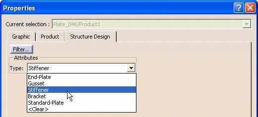
8 Do It Yourself (1/3) Run CATIA Open CATStructureDesignSample.CATfct ( \intel_a\resources\graphic) Select Shape Add a new attribute Attribute name: Vendor Attribute type: String With: Single Value Select Plate Add a new attribute Attribute name: Type Attribute type: String With: Discrete values Save your modifications and close the file 8

9 Do It Yourself (2/3) Go to \intel_a\startup\equipmentandsystems\discretevalues Create a new text file Call it: Type Open Type.txt Key in the following text End-Plate Gusset Stiffener Bracket Standard-Plate Use <Shift> <Enter> keys combination to jump to separate lines 9


10 Do It Yourself (3/3) Test your modifications Create a Product Place a Shape Place a Plate 10
11 Master Exercise: Administrating SR1 Step 3: Creating a Resolved Standard Section 120 min In this exercise you will: Create a new Section Create a new Design Table Resolved the Sections 11
 Rename it: AISC_Double_Unequal_Angles.")
 Change the Sketch of the section Create a new constraint to pilot the Clearance")
12 Do It Yourself (1/4) Create 2 directories: E:\ToBeResolved and E:\Resolved Copy AISC_Unequal_Angles.txt from \intel_a\startup\equipmentandsystems\structure\structuralcatalogs\aisc\desig ntables Into E:\ToBeResolved) Rename it: AISC_Double_Unequal_Angles.txt Edit it: Change PartNumber: Lxxx in 2Lxxxx Remove 'Code' column Open in CATIA the CATPart LShapeRND.CATPart ( \intel_a\startup\equipmentandsystems\structure\structuralcatalogs\sketchs) Change the Sketch of the section Create a new constraint to pilot the Clearance Modify the CATPart properties Product = AISC_Double_Unequal_Angles Save as AISC_Double_Unequal_Angles.CATPart Into E:\ToBeResolved) 12


 Click Open button Click Yes button If needed, you can")
13 Do It Yourself (2/4) Select the 'Design Table' icon Key-in 'AISC_Double_Unequal_Angles' as Name Select: 'Create a design table from a pre-existing file' Click OK button Select the file: AISC_Double_Unequal_Angles.txt Look in E:\ToBeResolved Files of type: Text files (*.txt) Click Open button Click Yes button If needed, you can open the AISC_Double_Unequal_Angles.CATPart 13


14 Do It Yourself (3/4) Click OK button The sketch should update Edit the Sketch Modify Point.2 and Point.8 Feature properties catstrwebbottomleft catstr prefix is mandatory. catstrwebbottomright Point.8 Point.2 14

15 Do It Yourself (4/4) Save your modifications Open a command prompt window Change to the directory...intel_a\code\command Structure of command: CATCloGenerateResolvedParts.bat -env file [-direnv dir] [-installdir dir] DirectoryPathIn [DirectoryPathOut -appl applname] Type the following command line: CATCloGenerateResolvedParts.bat -env R18_GA -direnv "C:\Documents and Settings\otv\Application Data\DassaultSystemes\CATEnv"D:\R18GA D:\PIPING_\TST_SR1\ToBeResolved D:\PIPING_\TST_SR1\Resolved -appl Structure Press Enter Copy the resolved CATParts in: (E:\TST_SR1\Structure\StructuralCatalogs\ModelsResolved). if process fails due to any reason, the env file gets consumed in process. 15
16 Master Exercise: Administrating SR1 Step 4: Modifying the Structure Specification Material Catalog 90 min In this step you will: Create a new 'Grade' chapter Create two new 'Profile' and 'Plates' chapter Insert the newly resolved Sections Insert new Thicknesses manage a list of 'Favorite' profiles 16

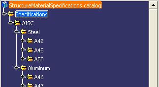
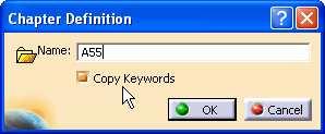

17 Do It Yourself (1/5) Open the StructureSpecificationMaterial.catalog found in: \intel_a\startup\equipmentandsystems\structure\structuralcatalogs\materials Activate the AISC/Steel chapter Create a new 'Grade' chapter Check the Copy Keywords option Activate the newly created Chapter Create 2 new Families: Profile, and Plates 17


18 Do It Yourself (2/5) Activate 'Profile' family Add new Components Click 'Select Document' Select a resolved section Look in E:\TST_SR1\Structure\StructuralCatalogs\ModelsResolved Select the Sections previously created Click 'Open' button Click OK button The section is added to the catalog Repeat the previous Steps to add more than one section into the 'Profile' family 18


19 Do It Yourself (3/5) Activate 'Plates' family Add new 'Generative Part' Click 'Select Document' Select the Thickness part Look in E:\TST_SR1\Structure\Structural Catalogs\Material Click 'Open' button Click OK button The allowed thicknesses are added to the catalog 19


20 Do It Yourself (4/5) Activate 'Profile' family Select a profile in the list Right-click to open the 'Description Definition' window Select 'Keyword values' tabpage Select 'SpecMode' field Click button Select N value Click OK button The SpecMode of the profile is modified 20


21 Do It Yourself (5/5) Test your newly modified Catalog Open a new Product Create a Grid Browse your Catalog Change the Anchor point 21
 Test your")
22 Master Exercise: Administrating SR1 Step 5: Creating a Standard End-Cut 180 min In this step you will : Define the End-Cut Context Create End-Cut Inputs Create End-Cut Construction Elements Create End-Cut Geometry Create End-Cut User Define Feature (UDF) Test your UDF 22


23 Do It Yourself (1/10) Load Standard_Endcut_Context.CATProduct Add Publications Save the model If needed, open Starter_Model_For_Tee_Shape_Publications_Creation.CATPart 23


24 Do It Yourself (2/10) If needed refer Step1-Publications_Creation.avi from downloaded files. Insert geometrical set 'Inputs' Extract the following edge\faces of the member, selecting from the publications: Rename them Save the model If needed, open Starter_Model_For_Tee_Shape_Inputs_Creation.CATPart 24

25 Do It Yourself (3/10) If needed refer Step2-Inputs_Creation.avi from downloaded files. Insert Construction Elements Geometrical Set. Create the midpoint on Shape_Edge_MoldedFlange1. Create Plane.1 normal to Create Plane.2 Tangent to surface through Point.2. Create Plane.3 Offset from Plane.2 at -20mm from it. Create Plane.4 offset from Plane.2 at 40mm from it. Create Plane.5 offset from Plane.2 at 80mm from it. Create Plane.6 Parallel to through Point.2. Create Intersect of Plane.1 with Create Intersect of Intersect.1 with Plane.5. Create Plane.7 tangent to through Intersect.2. Create Plane.8 and Plane.9 at an offset of 20mm and 60mm from Plane.7. Project Intersect.2 to Plane.8 Intersect Plane.9 with Plane.4 Intersect Intersect.3 with Plane.1 25


26 Do It Yourself (4/10) Intersect Plane.8 with Plane.4 Intersect Intersect.5 with Plane.1 Create a circle with center at Intersect.6 on Plane.1 with radius 40mm Split the Circle.1 with Plane.8 and Plane.4 Insert Instantiate from document Insert Positioned Sketch 26
 Start the")


27 Do It Yourself (5/10) Start the sketch as per cutout expected Coincide the ends Delete the H & V constrains Make top line of sketch to Plane.7 27


28 Do It Yourself (6/10) Similarly make bottom line of sketch to Plane.9 Coincide the straight side of sketch with Plane.3 Join the circular split with Sketch.2 Introduce Parameters Associate Parameters Save the model If needed, open Starter_Model_For_Tee_Shape_Construction_Elements.CATPart 28


29 Do It Yourself (7/10) If needed refer Step3-Construction_Elements.avi from downloaded files. Select the Pocket command Create the pocket using Join.1 Hide Construction Elements Save the model If needed, open Starter_Model_For_Tee_Shape_Poket_Definition.CATPart 29

30 Do It Yourself (8/10) If needed refer Step4-Pocket_Definition.avi from downloaded files. Select Insert > Knowledge Template Rename the Userfeature Select the Pocket, Construction Elements, Parameters, relations 30


31 Do It Yourself (9/10) Publish Necessary Parameters Save the model If needed, open Starter_Model_For_Tee_Shape_ UDF_Definition.CATPart 31


32 Do It Yourself (10/10) If needed refer Step5-UDF_Definition.avi from downloaded files. Open StructureDetailingFeatures.catalog available in \intel_a\startup\equipmentandsystems\stru cture\detailingfeatures The working model should also be open in same session Activate the family to house the EndCut Select the add components icon Click on Select The Endcut in the working CATPart Check the Path in the Catalog Click OK and Save the Catalog Open a new session, Test for integrity Change Necessary Parameters for expected results 32
 Test your UDF")
33 Master Exercise: Administrating SR1 Step 6: Creating a Contextual End-Cut 180 min In this step you will create: Define the End-Cut Context Create End-Cut Inputs Create End-Cut Construction Elements Create End-Cut Geometry Create End-Cut User Define Feature (UDF) Test your UDF 33
 Go to Tools\Customize\Commands\All Commands Drag and drop the Manage Structure Publication command into the session toolbar")
34 Do It Yourself (1/31) Note: In this example an I section is shown First, Ensure that Managing Publications is on (SR1 workbench must be active) Go to Tools\Customize\Commands\All Commands Drag and drop the Manage Structure Publication command into the session toolbar 34


35 Do It Yourself (2/31) Create the three shapes under a product and rename them as shown, 1000mm long Note that the second and the third shapes overlap in space Save the model If needed, open I-Notching_ Environment_Definition.CATProduct 35


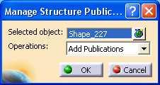
36 Do It Yourself (3/31) If needed refer Step1-Environment_Definition.avi from downloaded files. Activate the Root product and select all members Click Manage Structure Publication command and add 3 publications Save the model 36


37 Do It Yourself (4/31) Activate the Part of the Active Object section Change the workbench to GSD if necessary Double-click the Extract command Start with the face of the Shape1 as shown, Click OK 37


38 Do It Yourself (5/31) Create extracts for all 16 faces of the section moving counterclockwise Note the surfaces added under External References and Extracts under StrSkeleton Complete the 16 extracts
 Hide the")


39 Do It Yourself (6/31) Hide the Active Object member Keep the Part of the hidden r-shape activated Continue Extracting the four sides of the shape for Input creation as shown 39

40 Do It Yourself (7/31) Start renaming the External Reference surfaces as per their publication nomenclature, via contextual menu \ Properties, starting with 'Shape1_' Note that for multiple shapes, the convention is to start with 'Shape_' Repeat for the first 16 references created from the active object 40

41 Do It Yourself (8/31) Use the 'Shape_' starting syntax to similarly name the References created from the shape for Input creation 41


42 Do It Yourself (9/31) Select the first set of references created from the Active Object and Isolate them 42


43 Do It Yourself (10/31) Activate the Root product and Delete the Shape_for_Internal_Input_Creation. Select all the Extracts under the StrSkeleton of the Active Object and Delete them. Close the warning message. Note that they are in relation to the external references. Save the product. If needed, open I-Notching_Inputs_Creation.CATProduct 43


44 Do It Yourself (11/31) If needed refer Step2-Inputs_Creation.avi from downloaded files. Activate the r-shape part of the Active Object Insert an Ordered Geometrical Set and name it Construction Elements Create an intersect between the first two elements of the External References 44

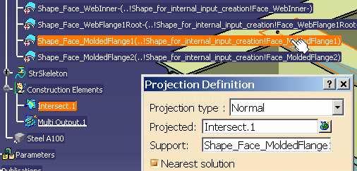
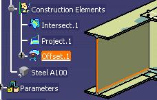

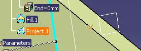
45 Do It Yourself (12/31) Project the intersect to the Shape_Face_ModedFlange1 Rename the Isolated External References to Inputs Create an Offset of 0mm from the Input element as shown 45


46 Do It Yourself (13/31) Activate the r-shape part of the Active Object Select Insert\ Select 'OrientedCurve.CATPart' from the path shown Associate the Project.1 and Offset.1 as shown (select from the Product Tree),Click OK 46


47 Do It Yourself (14/31) Similarly, project the Intersect.1 onto the Shape_Face_MoldedFlange2, Insert Curve Orientation Create a line between the starting points of the Curve Orientation lines Create an offset of 0mm from Instantiate 'OrientedCurve.CATPart' between the Line.5 and Offset.2 to create Line.3 47


48 Do It Yourself (15/31) Create a plane (Plane.1) through the Line.1 and Line.2 Create Intersections between the Plane.1 and the 16 elements under Create Intersection between 48

49 Do It Yourself (16/31) Create Intersection between Create Offset of 0mm from Shape_Face_WebInner- Instantiate 'CurveOrientation.CATPart' between the Intersect.18 and Offset.3 to create Line.4 Instantiate 'CurveOrientation.CATPart' between the Intersect.19 and Offset.3 to create Line.5 49


50 Do It Yourself (17/31) Create a plane (Plane.2) through the Line.4 and Line.5 Content>Create 2 middle points on Multi Output.1\ Intersect.2 and on Multi Output.1\ Intersect.10 Create the midpoint of the above two points Create a plane through Point.26 parallel to Plane.2 50


51 Do It Yourself (18/31) Create a Line.9 from Point.26 in the direction of Line.1, 100mm long Create a Point.27 using Point on Curve Line.9, Geodesic, Ratio=1 Create Plane.4 through Point.27 parallel to Plane.3 Intersect Plane.4 with Line.1 Create using four parameters of type length with default values as shown 51

52 Do It Yourself (19/31) Select the button Position the sketch as shown 52


53 Do It Yourself (20/31) Create the basic sketch as per the cutout expected Constrain the top and bottom of the cutout with the intersects parallel to the Flange1\2Inner- Constrain the cutout top & bottom ends with their respective parallel sketch exteriors 53
 Constrain")


54 Do It Yourself (21/31) Constrain the horizontal depth of the cutout Constrain the horizontal dimension of the sketch Constrain the end of the sketch with Constrain the two snipes of the cutout 54

 Now, delete all &")
55 Do It Yourself (22/31) Set angular constrains between the snipes and Line.1 \ Line.2 Note: Delete a coincident constrain if necessary The sketch should be fully constrained now (green) Now, delete all & constrains Re-constrain to add an angle as necessary 55

\Intersect.7`,`Construction Elements\Multi Output.4 (Intersect)\Intersect.5`) /2+Df2) - (distance(`construction Elements\Multi Output.")

56 Do It Yourself (23/31) Associate the length of the snipes of the sketch with the Snipe parameter Associate the constrain 'cutout top\bottom with the intersect parallel to the Flange1Inner-'with Df1 Associate the constrain 'cutout bottom with the intersect parallel to the Flange2Inner-' with Df2 Apply the following formula (distance(`construction Elements\Multi Output.4 (Intersect)\Intersect.7`,`Construction Elements\Multi Output.4 (Intersect)\Intersect.5`) /2+Df2) - (distance(`construction Elements\Multi Output.4 (Intersect)\Intersect.10`,`Construction Elements\Multi Output.4 (Intersect)\Intersect.2`)/2 + Dw ) Use Step3-Elements_of_Construction.avi from downloaded files for details of above formula creation. 56


57 Do It Yourself (24/31) Modify the constrain between the side of the Endcut and of the sketch to zero. The farthest side of the Endcut should be inline with Plane.4 57
\Intersect.10`,`Construction Elements\Multi Output.1 (Intersect)\Intersect.2`)\2 + Dw) Note the conventions followed Exit the sketcher Use Step3-Elements_of_Construction.")
58 Do It Yourself (25/31) Add formula as below (distance(`construction Elements\Multi Output.1 (Intersect)\Intersect.7``Construction Elements\Multi Output.1 (Intersect)\Intersect.5`)\2+Df2) - (distance(`construction Elements\Multi Output.1 (Intersect)\Intersect.10`,`Construction Elements\Multi Output.1 (Intersect)\Intersect.2`)\2 + Dw) Note the conventions followed Exit the sketcher Use Step3-Elements_of_Construction.avi from downloaded files for details of above formula creation. 58
\Intersect.")
\2 + Df2 Save the Product If needed, open I-Notching_Elements_of_Construction.")
59 Do It Yourself (26/31) Select Line.9 Add a formula: distance(`construction Elements\Multi Output.1 (Intersect)\Intersect.7`, `Construction Elements\Multi Output.1 (Intersect)\Intersect.5`)\2 + Df2 Save the Product If needed, open I-Notching_Elements_of_Construction.CATProduct Use Step3-Elements_of_Construction.avi from downloaded files for details of above formula creation. 59


60 Do It Yourself (27/31) If needed refer Step3-Elements_of_Construction.avi from downloaded files. Ensure that the r-shape Part is activated in the Active Object Change workbench to Part Design Select the Slot command Select the Sketch.2 for Profile and Line.6 for Center curve Hide Inputs, External Refs and Construction Elements Change Parameters to manipulate geometry Save the product If needed, open I-Notching_ Slot_Creation.CATProduct 60

61 Do It Yourself (28/31) If needed refer Step4-Slot_Creation.avi from downloaded files. Ensure that the r-shape Part is activated in the Active Object Select Insert > Knowledge Templates >UserFeature Rename the Userfeature as necessary Select 61


62 Do It Yourself (29/31) Publish the Parameters that will drive the UDF Check Outputs Save the product If needed, open I-Notching_UDF_Creation.CATProduct 62
63 Do It Yourself (30/31) If needed refer Step5-UDF_Creation.avi and Step6-UDF_Instantiation.avi from downloaded files. Open StructureDetailingFeatures.catalog available in \intel_a\startup\equipmentandsystems\structure\detailingfeat ures The working model must also be open in same session Activate the family to house the EndCut Select the add components icon Click Select The I-Notching UDF in the working CATPart Check the Path in the Catalog Click OK and Save the Catalog Close the opened documents Open a new session, Test for integrity Change Necessary Parameters for expected results 63

64 Do It Yourself (31/31) There Must not be any Internal Part object associated to the sketch CORRECT WRONG 64
 Test your UDF")
65 Master Exercise: Administrating SR1 Step 7: Creating a Slot 180 min In this step you will create : Define the Slot Context Create Slot Inputs Create Slot Construction Elements Create Slot Geometry Create Slot User Define Feature (UDF) Test your UDF 65

 Select the xy plane and sketch the")


66 Do It Yourself (1/15) Open a new CATPart, name it Insert a rename it as Tee_Section_Shape_Body Insert Geometrical Set after changing to rename it to (Plate_Geometry) Select the xy plane and sketch the plate section (in this case, the ends are 800mm apart) Select the yz plane and sketch the height of the plate (800 mm length) Select the sweep button and create the plate surface Change to and create a 10mm thick surface Save the model 66


67 Do It Yourself (2/15) Open DSA_SLOT_Environment_Definition.CATPart Change to if necessary and create a new geometrical Set Extract the two faces of the plate thick surface Rename them as necessary Similarly extract and rename to create the following: Refer Step1-Environment_Definition.avi from downloaded files. Save If needed, open DSA_SLOT_ Inputs_Creation.CATPart 67
68 Do It Yourself (3/15) If needed refer Step2-Inputs_Creation.avi from downloaded files. Create new Geometrical set Create 0mm offsets from to create Insert a new Length Parameter Plate Thickness Associate it to the distance between the offsets created (Refer AVI ) 68


69 Do It Yourself (4/15) Create another offset from Associate it to ½ Plate Thickness and rename to Midsurface_Plate Create the following Intersects: 69

70 Do It Yourself (5/15) Create the midpoints of Intersect.2 and Intersect.5: Create the following Planes and rename 70

71 Do It Yourself (6/15) 71
 Create the following")
72 Do It Yourself (7/15) Insert 3 New Parameters of Type Length Associate the Parameters to existing planes Create ( _ in-between ) Create the following Intersects 72


73 Do It Yourself (8/15) Insert a Polyline Close Polyline Edit formula for: Intersect.9 Intersect.10 associate with Renamed Parameter Radius Create Plane.13 Create Project.1 Save the model If needed, open DSA_SLOT_Elements_of_Construction.CATPart 73

74 Do It Yourself (9/15) If needed refer Step3-Elements_of_Construction_1.avi from downloaded files. Hide and all except under Change to if necessary Select Create Pocket as follows Save the model If needed, open DSA_SLOT_ Slot_Creation.CATPart 74

75 Do It Yourself (10/15) If needed refer Step4-Slot_Creation.avi from downloaded files. Insert Key in a new name Select UDF_GEOMETRY_DEFINITION to get the following 75

76 Do It Yourself (11/15) Click on the elements under Inputs of Contents to switch them to Selected components. 76

77 Do It Yourself (12/15) Next select each of The Internal Components section should include Publish the following in tab Save the model. If needed, open DSA_SLOT_ UDF_Creation.CATPart 77

78 Do It Yourself (13/15) If needed refer Step5-UDF_Creation_Create UDF - Slot.avi and Step5-UDF_Creation_Look_For_Unused_Geometry.avi from downloaded files. Open StructureDetailingFeatures.catalog available in \intel_a\startup\equipmentandsystems\structure\detailingfeatures The working model should also be open in same session Activate the family to house the Slot Select the add components icon Click on Select The DSA_Slot in the working CATPart Check the Path in the Catalog Click OK and Save the Catalog Close the opened documents Open a new session, Test for integrity Change Necessary Parameters for expected results 78


79 Do It Yourself (14/15) If needed, open Step6-UDF_Instantiation.avi Note that if an icon was created during Template creation, it will show up under Preview in the Catalog 79

80 Do It Yourself (15/15) The slot should be ready to instantiate on straight \ curved plates 80

81 Master Exercise: Administrating SR1 Step 8: Creating a Small Assembly (T-Chock) 180 min In this step you will create : Define the Assembly Context Create T-Chock Inputs Create T-Chock Construction Elements Create T-Chock Geometry Create T-Chock Document Template Test your Assembly 81


82 Do It Yourself (1/20) If needed refer Step1-Context_Definition.avi from downloaded files. Start with a new CATProduct, naming it Create a WT8X25 section 82


83 Do It Yourself (2/20) Introduce a new CATProduct and name it T-Chock_Definition_NDA Introduce a new CATPart under the above CATProduct Click No in the New Part prompt Hide the xyz planes in the T-Chock_Skeleton.CATPart Save the Product If needed, open T-Chock_Context_Context_Definition.CATProduct 83


84 Do It Yourself (3/20) If needed refer Step2-Inputs_Creation.avi from downloaded files. Rename the shape to Shape1 Add Publication for Shape1 Extract the following from the Shape1 \ Publications 84
 Create a")

85 Do It Yourself (4/20) Create a Plane.1 using the options shown Isolate the Plane 85
 Replace the")


86 Do It Yourself (5/20) Replace the Shape.x with the respective ref surface names in Feature Properties Delete the 86


87 Do It Yourself (6/20) Select the contents of the External references and Isolate them Cut Paste the Plane.1 into Isolated External References Delete all extracts Rename Isolated External References to Inputs Save the product Close Session If needed, open T-Chock_Definition_ Inputs_Creation.CATProduct 87


88 Do It Yourself (7/20) If needed refer Step3-Construction_Elements_Creation.avi from downloaded files. Open only the Rename Plane.1 to Rename the existing to Create intersects as follows 88

89 Do It Yourself (8/20) Create Plane.2 100mm offset from Support_Plane Create Insert Insert OrientedCurve.CATPart from \intel_a\startup\equipmentandsystems\structure\detailingfeatures\utilityudfs. Rename it as Line.1 89
 Refer avi file. distance(`construction Geometry Left\Line.1\End`,`Construction Geometry Left\Line.")
90 Do It Yourself (9/20) Create an Offset.2 from Insert OrientedCurve.CATPart and rename as Line.2 Create a Point on Line.1 (in this case it is shown as Point.19) Refer avi file. distance(`construction Geometry Left\Line.1\End`,`Construction Geometry Left\Line.2\Start`)*cos(45deg) 90


91 Do It Yourself (10/20) Click Yes at the following prompt Create a Line.3 using the previously created Point.19 and Line.2 91


92 Do It Yourself (11/20) Create a Line.4 using the previously created End of Line.2 and Line.1 Use the Reverse Direction button if necessary 92


93 Do It Yourself (12/20) Activate T-Chock_Definition_NDA.CATProduct Use to create a new Parameter named as Nose of type Length and default value 25mm Activate the T-Chock_Skeleton.CATPart Double click on the end of Line.3 Right Click and Edit Formula Associate the external parameter Nose Similarly associate the End of Line.4 with Nose 93


94 Do It Yourself (13/20) Create a Line.5 to join Line.1 and Line.2 Create a Point at the end of Line.3 In this model Create another Point at the end of Line.4 In this model Create a Line.6 to join the new two points 94


95 Do It Yourself (14/20) Use the Fill command to create a surface for the chock Project Start of Line.1 onto Plane.2 Instantiate OrientedSurface.CATPart from \intel_a\startup\equipmentandsystems\structure\detailingfeatures\utilityudfs. Rename as Surface.1 Hide the Fill.1 95

96 Do It Yourself (15/20) Insert \ Operations Activate the Root Create a Name it Invert Reactivate the Part Associate the to Repeat steps of creation of Construction Geometry Left to create the Note: The need not be created again Save the product 96
using option and Rename the plates")
97 Do It Yourself (16/20) Introduce a Parameter named as Plate_Thickness of Type Length to define Chock Thickness Go to Tools \ Select the Rename them Activate T-Chock_Definition_NDA Switch to SR1 workbench Create Chocks (Plates )using option and Rename the plates 97


98 Do It Yourself (17/20) Associate both the Chock Thickness to the Plate_Thickness Parameter Hide construction geometry Save the model If needed, open T-Chock_Definition_Construction_Elements_Creation.CATProduct 98


99 Do It Yourself (18/20) If needed refer Step4-Chocks_Creation.avi from downloaded files. Make graphic changes as necessary Ensure T-Chock_Definition_NDA is activated Insert Add Inputs 99


100 Do It Yourself (19/20) If needed refer Step5-Template_Creation.avi and Step6-Template_Instantiation.avi from downloaded files. In the Tab, do an then select Parameters Add the created Parameters Click OK to create the Rename the Document Template as necessary Save T-Chock_Definition_NDA.CATProduct Open StructureDetailingFeatures.catalog available in \intel_a\startup\equipmentandsystems\structure\detailingfeatures Select the appropriate family Associate using Save the Catalog If needed, open T-Chock_Context_Chocks_Creation.CATProduct 100

101 Do It Yourself (20/20) After instantiating the chocks, if parameters need to be changed repeatedly and no change in graphics are noted, activate the different levels of the chock definition and update. 101
Equipment Support Structures
 Equipment Support Structures Overview Conventions What's New? Getting Started Setting Up Your Session Creating a Simple Structural Frame Creating Non-uniform Columns Creating Plates with Openings Bracing
CATIA Surface Design
 CATIA V5 Training Exercises CATIA Surface Design Version 5 Release 19 September 2008 EDU_CAT_EN_GS1_FX_V5R19 Table of Contents (1/2) Creating Wireframe Geometry: Recap Exercises 4 Creating Wireframe Geometry:
Equipment Support Structures
 Page 1 Equipment Support Structures Preface Using This Guide Where to Find More Information Conventions What's New? Getting Started Setting Up Your Session Creating a Simple Structural Frame Creating Non-uniform
Mechanical Design V5R19 Update
 CATIA V5 Training Foils Mechanical Design V5R19 Update Version 5 Release 19 August 2008 EDU_CAT_EN_MD2_UF_V5R19 1 About this course Objectives of the course Upon completion of this course you will be able
Preface. Version 5 Release 5. Mold Tooling Design
 Version 5 Release 5 Mold Tooling Design Preface Getting Started Basic Tasks Advanced Tasks Customization Workbench Description Glossary Index Preface The CATIA Version 5 Mold Tooling Design application
Lesson 3: Surface Creation
 Lesson 3: Surface Creation In this lesson, you will learn how to create surfaces from wireframes. Lesson Contents: Case Study: Surface Creation Design Intent Stages in the Process Choice of Surface Sweeping
Electrical 3D Design & Documentation
 Electrical 3D Design & Documentation Page 1 Overview Conventions User Tasks Using Electrical 3D Design & Documentation Entering the Electrical Assembly Design Workbench Entering the Electrical Part Design
Additional Exercises. You will perform the following exercises to practice the concepts learnt in this course:
 Additional Exercises You will perform the following exercises to practice the concepts learnt in this course: Master Exercise : Mobile Phone Plastic Bottle Exercise 1 Master Exercise : Mobile Phone In
CATIA V5 Parametric Surface Modeling
 CATIA V5 Parametric Surface Modeling Version 5 Release 16 A- 1 Toolbars in A B A. Wireframe: Create 3D curves / lines/ points/ plane B. Surfaces: Create surfaces C. Operations: Join surfaces, Split & Trim
Circuit Board Design Version 5 Release 13. Circuit Board Design
 Circuit Board Design Page 1 Overview Conventions What's New? Getting Started Accessing the Circuit Board Workbench Creating a Board Pocket and Holes Constraint Area Exporting Data Importing Data User Tasks
COPYRIGHT DASSAULT SYSTEMES Version 5 Release 19 January 2009 EDU-CAT-EN-ASL-FS-V5R19
 CATIA Training CATIA Aerospace Sheet Metal Design Detailed Steps COPYRIGHT DASSAULT SYSTEMES Version 5 Release 19 January 2009 EDU-CAT-EN-ASL-FS-V5R19 Table of Contents Additional Exercise: Aerostructure...3
Aerospace Sheetmetal Design
 Aerospace Sheetmetal Design Page 1 Overview Conventions What's New? Getting Started Entering the Aerospace SheetMetal Design Workbench Defining the Aerospace SheetMetal Parameters Creating a Web from a
CATIA Electrical Space Reservation TABLE OF CONTENTS
 TABLE OF CONTENTS Introduction...1 Manual Format...2 Electrical Reservations...3 Equipment Reservations...5 Pathway Reservations...31 Advanced Reservations...49 Reservation Analysis...67 Clash...69 Sectioning...73
Electrical Harness Installation
 Electrical Harness Installation Page 1 Overview Conventions What's New? Getting Started Entering the Workbench Setting Up the Options Creating a Bundle Segment Document Creating Construction Points Defining
Electrical Harness Flattening
 Electrical Harness Flattening Overview Conventions What's New? Getting Started Accessing the Electrical Harness Flattening Workbench Defining the Harness Flattening Parameters Extracting Data Flattening
Aerospace Sheet Metal Design
 CATIA V5 Training Foils Aerospace Sheet Metal Design Version 5 Release 19 January 2009 EDU_CAT_EN_ASL_FI_V5R19 1 About this course Objectives of the course Upon completion of this course you will be able
COPYRIGHT DASSAULT SYSTEMES Version 5 Release 19 January 2009 EDU-CAT-EN-TG1-FS-V5R19
 CATIA Training CATIA Tooling Design COPYRIGHT DASSAULT SYSTEMES Version 5 Release 19 January 2009 EDU-CAT-EN-TG1-FS-V5R19 Table of Contents 1. Master Exercise: Phone Handset...3 2. Editing Components...15
COPYRIGHT DASSAULT SYSTEMES Version 5 Release 19 January 2009 EDU-CAT-EN-KBE-A-FS-V5R19
 CATIA Training Knowledge Based Engineering: Advanced COPYRIGHT DASSAULT SYSTEMES Version 5 Release 19 January 2009 EDU-CAT-EN-KBE-A-FS-V5R19 Table of Contents Master Exercise: Strap tension optimization...3
Structure Preliminary Layout
 Structure Preliminary Layout Overview Conventions What's New? Getting Started Setting Up Your Session Defining the Hull Form Setting Up Your Grid Creating Molded Forms Creating a Compartment Creating Boundaries
Structure Preliminary Layout
 Page 1 Structure Preliminary Layout Preface Using This Guide Where to Find More Information What's New? Getting Started Setting Up Your Session Defining the Hull Form Setting Up Your Grid Creating Molded
Lesson 6: Work in Multi-Model Environment with Surface
 Lesson 6: Work in Multi-Model Environment with Surface In this lesson, you will learn how to work in Multi-Model Environment with Surface. Lesson Contents: Case Study: Multi-Model Environment with Surface
Solidworks 2006 Surface-modeling
 Solidworks 2006 Surface-modeling (Tutorial 2-Mouse) Surface-modeling Solid-modeling A- 1 Assembly Design Design with a Master Model Surface-modeling Tutorial 2A Import 2D outline drawing into Solidworks2006
SheetMetal Design Version 5 Release 13. SheetMetal Design
 SheetMetal Design Page 1 Overview Conventions What's New? Getting Started Entering the Workbench Defining the Parameters Creating the First Wall Creating the Side Walls Creating a Cutout Creating Automatic
Compartment and Access
 Compartment and Access Preface Using This Guide What's New? Getting Started Entering the Workbench Set Correct Working Units and Grid Saving Documents User Tasks Creating/Modifying Wall Systems Building
Structural & Thermal Analysis Using the ANSYS Workbench Release 12.1 Environment
 ANSYS Workbench Tutorial Structural & Thermal Analysis Using the ANSYS Workbench Release 12.1 Environment Kent L. Lawrence Mechanical and Aerospace Engineering University of Texas at Arlington SDC PUBLICATIONS
Aerospace Sheet Metal Design
 CATIA V5 Training Foils Aerospace Sheet Metal Design Version 5 Release 19 January 2009 EDU_CAT_EN_ASL_FF_V5R19 1 About this course Objectives of the course Upon completion of this course you will be able
Chapter 2 Parametric Modeling Fundamentals
 2-1 Chapter 2 Parametric Modeling Fundamentals Create Simple Extruded Solid Models Understand the Basic Parametric Modeling Procedure Create 2-D Sketches Understand the "Shape before Size" Approach Use
Create Complex Surfaces
 Create Complex Surfaces In this lesson, you will be introduced to the functionalities available in the Generative Surface Design workbench. Lesson content: Case Study: Surface Design Design Intent Stages
Lesson 4: Surface Re-limitation and Connection
 Lesson 4: Surface Re-limitation and Connection In this lesson you will learn how to limit the surfaces and form connection between the surfaces. Lesson contents: Case Study: Surface Re-limitation and Connection
Compartment and Access
 Compartment and Access Page 1 Preface Using This Guide What's New? Getting Started Entering the Workbench Set Correct Working Units and Grid Saving Documents User Tasks Creating/Modifying Wall Systems
Fastening Review Overview Basic Tasks DMU Fastening Review Interoperability Workbench Description Customizing Index
 Fastening Review Overview Conventions Basic Tasks Displaying Joined Parts in a Balloon Running the Fastening Rules Analysis Reporting Creating Structural Reports Creating Flat Reports DMU Fastening Review
Electrical Library Version 5 Release 13. Electrical Library
 Electrical Library Page 1 Overview Conventions What's New? Getting Started Entering the Electrical Part Design Workbench Defining a Single Insert Connector Defining a Cavity Connection Point Entering Electrical
Structural & Thermal Analysis using the ANSYS Workbench Release 11.0 Environment. Kent L. Lawrence
 ANSYS Workbench Tutorial Structural & Thermal Analysis using the ANSYS Workbench Release 11.0 Environment Kent L. Lawrence Mechanical and Aerospace Engineering University of Texas at Arlington SDC PUBLICATIONS
3 AXIS STANDARD CAD. BobCAD-CAM Version 28 Training Workbook 3 Axis Standard CAD
 3 AXIS STANDARD CAD This tutorial explains how to create the CAD model for the Mill 3 Axis Standard demonstration file. The design process includes using the Shape Library and other wireframe functions
Exercise Guide. Published: August MecSoft Corpotation
 VisualCAD Exercise Guide Published: August 2018 MecSoft Corpotation Copyright 1998-2018 VisualCAD 2018 Exercise Guide by Mecsoft Corporation User Notes: Contents 2 Table of Contents About this Guide 4
Lesson 14 Blends. For Resources go to > click on the Creo Parametric Book cover
 Lesson 14 Blends Figure 14.1 Cap OBJECTIVES Create a Parallel Blend feature Use the Shell Tool Create a Swept Blend REFERENCES AND RESOURCES For Resources go to www.cad-resources.com > click on the Creo
Parametric Modeling with NX 12
 Parametric Modeling with NX 12 NEW Contains a new chapter on 3D printing Randy H. Shih SDC PUBLICATIONS Better Textbooks. Lower Prices. www.sdcpublications.com Powered by TCPDF (www.tcpdf.org) Visit the
Knowledge Advisor Overview What's New? Getting Started User Tasks
 Knowledge Advisor Overview Conventions What's New? Getting Started Using Parameters Using Formulas Using Rules Using Checks User Tasks Working with Parameters Creating a Parameter Introducing Parameters
Lesson 14 Blends. For Resources go to > click on the Creo Parametric 2.0 Book cover
 Lesson 14 Blends Figure 14.1 Cap OBJECTIVES Create a Parallel Blend feature Use the Shell Tool Create a Hole Pattern REFERENCES AND RESOURCES For Resources go to www.cad-resources.com > click on the Creo
Parametric Modeling. With. Autodesk Inventor. Randy H. Shih. Oregon Institute of Technology SDC PUBLICATIONS
 Parametric Modeling With Autodesk Inventor R10 Randy H. Shih Oregon Institute of Technology SDC PUBLICATIONS Schroff Development Corporation www.schroff.com www.schroff-europe.com 2-1 Chapter 2 Parametric
DMU Engineering Analysis Review
 Page 1 DMU Engineering Analysis Review Preface Using This Guide Where to Find More Information Conventions What's New? Getting Started Inserting a CATAnalysis Document Using DMU Space Analysis From CATAnalysis
1. In the first step, the polylines are created which represent the geometry that has to be cut:
 QCAD/CAM Tutorial Caution should be exercised when working with hazardous machinery. Simulation is no substitute for the careful verification of the accuracy and safety of your CNC programs. QCAD/CAM or
Piping Design. Site Map Preface Getting Started Basic Tasks Advanced Tasks Customizing Workbench Description Index
 Piping Design Site Map Preface Getting Started Basic Tasks Advanced Tasks Customizing Workbench Description Index Dassault Systèmes 1994-2001. All rights reserved. Site Map Piping Design member member
CATIA V5 Training Foils
 CATIA V5 Training Foils Knowledge Advisor Version 5 Release 19 January 2009 EDU_CAT_EN_KWA_FI_V5R19 1 About this course Objectives of the course Upon completion of this course you will be able to: - Become
Advanced Meshing Tools
 Page 1 Advanced Meshing Tools Preface Using This Guide More Information Conventions What's New? Getting Started Entering the Advanced Meshing Tools Workbench Defining the Surface Mesh Parameters Setting
Intersecting Lamina. To complete this model you should have a working knowledge of Solidworks 2006/2009.
 Prerequisite knowledge Focus of lesson Problem To complete this model you should have a working knowledge of Solidworks 2006/2009. This lesson focuses on using SolidWorks to solve a geometrical problem.
Parametric Modeling with UGS NX 4
 Parametric Modeling with UGS NX 4 Randy H. Shih Oregon Institute of Technology SDC PUBLICATIONS Schroff Development Corporation www.schroff.com www.schroff-europe.com 2-1 Chapter 2 Parametric Modeling
Module 4A: Creating the 3D Model of Right and Oblique Pyramids
 Inventor (5) Module 4A: 4A- 1 Module 4A: Creating the 3D Model of Right and Oblique Pyramids In Module 4A, we will learn how to create 3D solid models of right-axis and oblique-axis pyramid (regular or
DMU Space Engineering Assistant User Guide
 DMU Space Engineering Assistant User Guide Overview Conventions What's New? Getting Started User Tasks Setting Up Your Session Running an Interference Analysis Workbench Description DMU Space Engineering
DMU Space Analysis Version 5 Release 13. DMU Space Analysis
 Page 1 DMU Space Analysis Preface Using This Guide More Information Conventions What's New? Getting Started Setting Up Your Session Measuring Minimum Distances Sectioning Detecting Clashes Measuring Between
1 awea.com.m y
 1 www.mawea.com.m y 2 www.mawea.com.m y Announcement (1.0) (1.1) LUM END of Support The support of LUM licensing technology was end on December 31 st 2013. This technology had been replaced by DSLS which
CATIA V5 Analysis. CATIA V5 Training Foils. CATIA V5 Analysis. Copyright DASSAULT SYSTEMES 1. Student Notes:
 CATIA V5 Training Foils CATIA V5 Analysis Version 5 Release 19 January 2009 EDU_CAT_EN_V5A_FF_V5R19 1 Lesson 1: Introduction to Finite Element Analysis About this Course Introduction CATIA is a robust
FreeStyle Shaper & Optimizer
 FreeStyle Shaper & Optimizer Preface What's New Getting Started Basic Tasks Advanced Tasks Workbench Description Customizing Glossary Index Dassault Systèmes 1994-99. All rights reserved. Preface CATIA
SOLIDWORKS: Lesson III Patterns & Mirrors. UCF Engineering
 SOLIDWORKS: Lesson III Patterns & Mirrors UCF Engineering Solidworks Review Last lesson we discussed several more features that can be added to models in order to increase their complexity. We are now
Education Curriculum Surface Design Specialist
 Education Curriculum Surface Design Specialist Invest your time in imagining next generation designs. Here s what we will teach you to give shape to your imagination. CATIA Surface Design Specialist CATIA
Lesson 2 Constructive Solid Geometry Concept. Parametric Modeling with I-DEAS 2-1
 Lesson 2 Constructive Solid Geometry Concept Parametric Modeling with I-DEAS 2-1 2-2 Parametric Modeling with I-DEAS Introduction In the 1980s, one of the main advancements in Solid Modeling was the development
Mechanical Design CATIA - Structure Design 1 (SR1) CATIA V5R20
 CATIA V5R20") Mechanical Design CATIA - Structure Design 1 (SR1) CATIA V5R20 Mechanical Design CATIA - Structure Design Rapidly design structures using catalogues of standard or custom sections Product overview CATIA
Mechanical Design CATIA - Structure Design 1 (SR1) CATIA V5R20 Mechanical Design CATIA - Structure Design Rapidly design structures using catalogues of standard or custom sections Product overview CATIA
DMU Space Engineering Assistant User Guide
 Page 1 DMU Space Engineering Assistant User Guide Overview Conventions What's New? Getting Started User Tasks Setting Up Your Session Running a Interference Workbench Description DMU Space Engineering
Systems Space Reservation
 Systems Space Reservation Preface Using This Guide What's New? Getting Started Enter the Workbench Create an Equipment Reservation Set Correct Working Units and Grid Changing the Current Axis Saving Documents
Autodesk Inventor Design Exercise 2: F1 Team Challenge Car Developed by Tim Varner Synergis Technologies
 Autodesk Inventor Design Exercise 2: F1 Team Challenge Car Developed by Tim Varner Synergis Technologies Tim Varner - 2004 The Inventor User Interface Command Panel Lists the commands that are currently
Autodesk Inventor 2019 and Engineering Graphics
 Autodesk Inventor 2019 and Engineering Graphics An Integrated Approach Randy H. Shih SDC PUBLICATIONS Better Textbooks. Lower Prices. www.sdcpublications.com Powered by TCPDF (www.tcpdf.org) Visit the
SOLIDWORKS 2018 Reference Guide
 SOLIDWORKS 2018 Reference Guide A comprehensive reference guide with over 250 standalone tutorials David C. Planchard, CSWP, SOLIDWORKS Accredited Educator SDC PUBLICATIONS Better Textbooks. Lower Prices.
DMU Engineering Analysis Review
 DMU Engineering Analysis Review Overview Conventions What's New? Getting Started Entering DMU Engineering Analysis Review Workbench Generating an Image Visualizing Extrema Generating a Basic Analysis Report
SPEOS CAA V5 Based Optical Shape Design V13.0
 SPEOS CAA V5 Based Optical Shape Design V13.0 Table of Contents Getting Started... 5 Changing the User Interface Language... 5 Managing Documents... 5 Features... 6 Parabolic Surface... 7 Parabolic Surface
FreeStyle Shaper Optimizer & Profiler
 FreeStyle Shaper Optimizer & Profiler Page 1 Preface Using This Guide More Information What's New? Getting Started Starting the FreeStyle Workbench Creating a First Surface Editing the Surface Creating
Publication Number spse01695
 XpresRoute (tubing) Publication Number spse01695 XpresRoute (tubing) Publication Number spse01695 Proprietary and restricted rights notice This software and related documentation are proprietary to Siemens
Product Structure Version 5 Release 13. Product Structure
 Product Structure Page 1 Site Map Preface Conventions What's New? Basic Tasks Entering the Product Structure Workbench Opening a CATProduct with a Progress Bar Selecting Products only Selecting Modes Inserting
Publication Number spse01695
 XpresRoute (tubing) Publication Number spse01695 XpresRoute (tubing) Publication Number spse01695 Proprietary and restricted rights notice This software and related documentation are proprietary to Siemens
Course Modules for CATIA V6 2013x Essentials for New Users Training Online:
 Course Modules for CATIA V6 2013x - 100 Essentials for New Users Training Online: 1 Launching CATIA V6 The PLM Story Import IGI Models (Essentials) Launching CATIA V6 Choosing a Security Context 2 V6 Navigation
Project 3. Top Down Design In Context. Below are the desired outcomes and usage competencies based upon the completion of this Project.
 Assembly Modeling with SolidWorks Project 3 Below are the desired outcomes and usage competencies based upon the completion of this Project. Project Desired Outcomes: 2AXIS-TRANSFER Assembly. PLATE-B Part.
4. If you are prompted to enable hardware acceleration to improve performance, click
 Exercise 1a: Creating new points ArcGIS 10 Complexity: Beginner Data Requirement: ArcGIS Tutorial Data Setup About creating new points In this exercise, you will use an aerial photograph to create a new
Electrical Wire Routing
 Electrical Wire Routing Page 1 Overview Conventions What's New? Getting Started Accessing the Workbench Creating the Bundle Selecting Systems with External Data Routing Wires from External Data User Tasks
Lesson 2: Wireframe Creation
 Lesson 2: Wireframe Creation In this lesson you will learn how to create wireframes. Lesson Contents: Case Study: Wireframe Creation Design Intent Stages in the Process Reference Geometry Creation 3D Curve
CATIA V5-6R2015 Product Enhancement Overview
 Click to edit Master title style CATIA V5-6R2015 Product Enhancement Overview John Montoya, PLM Technical Support March 2015 1 2010 Inceptra LLC. All rights reserved. Overview of Enhanced Products Overview
Electrical System Functional Definition
 Electrical System Functional Definition Overview Conventions What's New? Getting Started Creating a New System Creating Equipment Creating Connectors Creating a Signal Connecting Saving Your System User
Inventor 201. Work Planes, Features & Constraints: Advanced part features and constraints
 Work Planes, Features & Constraints: 1. Select the Work Plane feature tool, move the cursor to the rim of the base so that inside and outside edges are highlighted and click once on the bottom rim of the
Chapter 2 Parametric Modeling Fundamentals
 2-1 Chapter 2 Parametric Modeling Fundamentals Create Simple Extruded Solid Models Understand the Basic Parametric Modeling Procedure Create 2-D Sketches Understand the Shape before Size Approach Use the
Electrical Cableway Routing
 Electrical Cableway Routing Preface Using This Guide What's New? Getting Started Entering the Workbench Placing a Hanger Routing a Loft Through Hangers Placing a Conduit on a Run Saving Documents Updating
Multi-Axis Surface Machining
 CATIA V5 Training Foils Multi-Axis Surface Machining Version 5 Release 19 January 2009 EDU_CAT_EN_MMG_FI_V5R19 1 About this course Objectives of the course Upon completion of this course you will be able
An Introduction to Autodesk Revit Massing, Surface Divisions, and Adaptive Components
 An Introduction to Autodesk Revit Massing, Surface Divisions, and Adaptive Components Chad Smith KarelCAD, Australia AB2463-L As the Revit massing tools become more polished and robust, users are becoming
Advanced Part Machining
 CATIA V5 Training Exercises Advanced Part Machining Version 5 Release 19 January 2009 EDU_CAT_EN_AMG_FX_V5R19 1 Table of Contents (1/2) Exercise Presentation 4 CATIA Settings 5 Multi-Axis Flank Contouring:
Input CAD Solid Model Assemblies - Split into separate Part Files. DXF, IGES WMF, EMF STL, VDA, Rhino Parasolid, ACIS
 General NC File Output List NC Code Post Processor Selection Printer/Plotter Output Insert Existing Drawing File Input NC Code as Geometry or Tool Paths Input Raster Image Files Report Creator and Designer
Generative Shape Design
 Generative Shape Design Copyright DASSAULT SYSTEMES 2002 1 Exercise 60 min. The Knob In this exercise you will have the opportunity to model an appliance Knob starting from an empty model. You will create
Lesson 1 Parametric Modeling Fundamentals
 1-1 Lesson 1 Parametric Modeling Fundamentals Create Simple Parametric Models. Understand the Basic Parametric Modeling Process. Create and Profile Rough Sketches. Understand the "Shape before size" approach.
Autodesk Fusion 360 Training: The Future of Making Things Attendee Guide
 Autodesk Fusion 360 Training: The Future of Making Things Attendee Guide Abstract After completing this workshop, you will have a basic understanding of editing 3D models using Autodesk Fusion 360 TM to
전산응용설계 (Computer Aided Design)
") 전산응용설계 (Computer Aided Design) CATIA (Computer Aided Three dimensional Interactive Application) 기계자동차공학부자동차공학전공 Chapter 3. CATIA 기초 학습내용 : 객체선택 (Selecting Objects) 객체감추기와보이기 (Hiding and Showing objects)
전산응용설계 (Computer Aided Design) CATIA (Computer Aided Three dimensional Interactive Application) 기계자동차공학부자동차공학전공 Chapter 3. CATIA 기초 학습내용 : 객체선택 (Selecting Objects) 객체감추기와보이기 (Hiding and Showing objects)
ArcMap Editing Tips and Tricks. Sean Jones
 ArcMap Editing Tips and Tricks Sean Jones Overview Topics - Tuning your editing map - Creating features - Editing features and attributes - Aligning and editing coincident features - Addins Format - Software
A Comprehensive Introduction to SolidWorks 2011
 A Comprehensive Introduction to SolidWorks 2011 Godfrey Onwubolu, Ph.D. SDC PUBLICATIONS www.sdcpublications.com Schroff Development Corporation Chapter 2 Geometric Construction Tools Objectives: When
Introduction to SolidWorks for Technology. No1: Childs Toy
 Introduction to SolidWorks for Technology No1: Childs Toy Table of Contents Table of Contents... 1 Introduction... 2 Part Modelling: Cab... 3 Part Modelling: Base... 6 Part Modelling: Wheel... 12 Assembly:
ME009 Engineering Graphics and Design CAD 1. 1 Create a new part. Click. New Bar. 2 Click the Tutorial tab. 3 Select the Part icon. 4 Click OK.
 PART A Reference: SolidWorks CAD Student Guide 2014 2 Lesson 2: Basic Functionality Active Learning Exercises Creating a Basic Part Use SolidWorks to create the box shown at the right. The step-by-step
Chapter 4 Feature Design Tree
 4-1 Chapter 4 Feature Design Tree Understand Feature Interactions Use the FeatureManager Design Tree Modify and Update Feature Dimensions Perform History-Based Part Modifications Change the Names of Created
Memo Block. This lesson includes the commands Sketch, Extruded Boss/Base, Extruded Cut, Shell, Polygon and Fillet.
 Commands Used New Part This lesson includes the commands Sketch, Extruded Boss/Base, Extruded Cut, Shell, Polygon and Fillet. Click File, New on the standard toolbar. Select Part from the New SolidWorks
Laboratory Manual. CAM 3 Core & Cavity Design Injection molds
 Laboratory Manual CAM 3 Core & Cavity Design Injection molds Faculty of Mechanical Engineering and Robotics Department of Robotics and Mechatronics Dr. Eng. Zbigniew Śliwa Objective To create surface elements
Introduction to ANSYS DesignModeler
 Lecture 5 Modeling 14. 5 Release Introduction to ANSYS DesignModeler 2012 ANSYS, Inc. November 20, 2012 1 Release 14.5 Preprocessing Workflow Geometry Creation OR Geometry Import Geometry Operations Meshing
USING THE TRIBALL FOR POSITIONING
 USING THE TRIBALL FOR POSITIONING Although many important positioning tools are available, none are as versatile as the TriBall tool. This TriBall tool offers complete repositioning of many items: Shapes
Training Guide Getting Started with WorkXplore 3D
 Training Guide Getting Started with WorkXplore 3D Table of Contents Table of Contents 1 Training Guide Objectives 1-1 2 WorkXplore 3D Environment 2-1 3 Importing and Opening CAD Files 3-1 3.1 Importing
xcompare V5/V5 2.1.x Quick Start Guide
 xcompare V5/V5 2.1.x Quick Start Guide This guide helps you getting started with comparing documents with xcompare V5/V5 and analyzing their differences. Basics xcompare recognizes differences between
Autodesk Inventor Tips & Tricks Placing Features On
 1 Autodesk Inventor Tips & Tricks Placing Features On Cylindrical Shapes The adoption of parametric, feature based solid modeling will present many challenges to the new user as they are confronted for
Battery Holder. Chapter 9. Boat. A. Front Extrude. Step 1. Click File Menu > New, click Part and OK. SolidWorks 10 BATTERY HOLDER AA BOAT Page 9-1
 Chapter 9 Boat Battery Holder A. Front Extrude. Step 1. Click File Menu > New, click Part and OK. AA Step 2. Click Front (plane) in the Feature Manager and click Sketch from the Content toolbar, Fig. 1.
User Guide. mk Config
 User Guide mk Config mk Config Register 1.1. CD-Start 4 1.2. Installation 5 1.3. Start 6 1.4. Layout of user interface and functions 7 1.4.1. Overview 7 1.4.2. Part buttons 8 1.4.3. Menus 9 1.4.3.1. Export