Using ADS to Post Process Simulated and Measured Models. Presented by Leon Wu March 19, 2012
|
|
|
- Verity McCoy
- 6 years ago
- Views:
Transcription


1 Using ADS to Post Process Simulated and Measured Models Presented by Leon Wu March 19, 2012
2 Presentation Outline Connector Models From Simulation Connector Models From Measurement The Post processing, The Correlation Model Quality Factor Feature Selective Validation Channel Simulation Conclusions
3 Connector Models - Brief History Connector models started as simple lumped element models Evolved into distributed models including coupling Multiport microwave network simulation [S] Increased adoption of deembedded measurements for correlation 70 s - 80 s 80 s to 90 s 90 s to present 00 s to present

4 Connector Models From Simulation For this study, we consider a high density, open pin field array connector SEARAY SEAM/SEAF Series Up to 10 rows, 50 pins/row on.050 pitch (500 pins) Typically used in an offset GGSSGG pattern G GS SG GS SG G S SG GS SG GS S
5 Typical Development Process Mechanical Design using Solidworks beam design, wipe, tolerances, manufacturing, plating, assembly, SI 3D Model cleanup Knurl removal, void removal, etc. Simulation in full wave tool (CST Microwave Studio, HFSS) Model import, port setup, material definition, meshing No Interpretation of results Is it good enough? Yes End Beer drinking and celebration
6 Connector Models From Simulation What could possibly go wrong? Meshing Material parameters Port setup Geometry capture
7 Connector Models From Simulation What could possibly go wrong? Meshing Material parameters Port setup Geometry capture
8 Connector Models From Simulation What could possibly go wrong? Meshing Material parameters Port setup Geometry capture
9 Connector Models From Simulation What could possibly go wrong? Meshing Material parameters Port setup Geometry capture
10 Connector Models From Simulation What could possibly go wrong? Meshing Material parameters Port setup Geometry capture
11 Connector Models From Simulation What could possibly go wrong? Meshing Material parameters Port setup Geometry capture
12 Connector Models From Simulation What could possibly go wrong? Meshing Material parameters Port setup Geometry capture
13 Connector Models From Simulation What could possibly go wrong? Meshing Material parameters Port setup Coupled ports waveguide or discrete? Absorbing or perfect BC? Geometry capture Air voids? No data here just need Reference plane location? skill with the Footprint effects? full wave tools
14 Presentation Outline Connector Models From Simulation Connector Models From Measurement The Post processing, The Correlation Model Quality Factor Feature Selective Validation Channel Simulation Conclusions
15 Connector Models From Measurement Frequency Domain Differential Application - Insertion Loss Differential Application - FEXT Insertion Loss (db) Optimal Horizontal Optimal Vertical High Density Vertical Far-End Crosstalk (db) SEAM147,157_SEAF107,117 SEAM147,157_SEAF126,136 SEAM147,157_SEAF145, Frequency (GHz) Differential Application - NEXT Frequency (GHz) 0 Near-End Crosstalk (db) SEAM147,157_SEAM107,117 SEAM147,157_SEAM126,136 SEAM147,157_SEAM145, Frequency (GHz)
16 Connector Models From Measurement Time Domain (Post processing) 130 Differential Application - Impedance vs. Risetime 140 Differential Application - Impedance Impedance (Ohms) Impedance (ohms) psec 50 psec 100 psec 250 psec 500 psec Risetime (psec) Differential Application - NEXT Time (nsec) Differential Application - FEXT Crosstalk (%) psec 50 psec 100 psec 250 psec 500 psec Crosstalk (%) psec 50 psec 100 psec 250 psec 500 psec Time (nsec) Time (nsec)
17 Connector Models From Measurement What could possibly go wrong? Test board footprint (aka geometry capture) Insertion depth Soldering/attachment Calibration
 Insertion depth Soldering/attachment")

18 Connector Models From Measurement What could possibly go wrong? Test board footprint (aka geometry capture) Insertion depth Soldering/attachment Calibration * Note the data on the following three slides is for a 2 row FT5/FS5 Series connector. It is the only data that is not for the 16mm array SEAM/SEAF Series. Case 1 inboard via Case 2 outboard via
19 Connector Models From Measurement What could possibly go wrong? Test board footprint Insertion depth Soldering/attachment Calibration * Note the data on this slide is for a 2 row FT5/FS5 Series connector. It is the only data that is not for the 16mm array SEAM/SEAF Series.
20 Connector Models From Measurement What could possibly go wrong? Test board footprint Insertion depth Soldering/attachment Calibration * Note the data on this slide is for a 2 row FT5/FS5 Series connector. It is the only data that is not for the 16mm array SEAM/SEAF Series.
21 Connector Models From Measurement What could possibly go wrong? Test board footprint Insertion depth Soldering/attachment Calibration * Note the data on this slide is for a 2 row FT5/FS5 Series connector. It is the only data that is not for the 16mm array SEAM/SEAF Series.


22 Connector Models From Measurement What could possibly go wrong? Test board footprint Insertion depth Soldering/attachment Calibration Fully Mated * Note the data on this slide is for a 2 row FT5/FS5 Series connector. It is the only data that is not for the 16mm array SEAM/SEAF Series. Shift 19.7 mils
23 Connector Models From Measurement What could possibly go wrong? Test board footprint Insertion depth Soldering/attachment Calibration * Note the data on this slide is derived from simulation.
24 Connector Models From Measurement What could possibly go wrong? Test board footprint Insertion depth Soldering/attachment Calibration * Note the data on this slide is derived from simulation.
25 Connector Models From Measurement What could possibly go wrong? Test board footprint Insertion depth Soldering/attachment Calibration * Note the data on this slide is derived from simulation.


26 Connector Models From Measurement What could possibly go wrong? Test board footprint Insertion depth Soldering/attachment Calibration Middle of Pad Edge of Pad * Note the data on the following three slides is derived from simulation.
27 Connector Models From Measurement What could possibly go wrong? Test board footprint Insertion depth Soldering/attachment Calibration * Note the data on the following three slides is derived from simulation.
28 Connector Models From Measurement What could possibly go wrong? Test board footprint Insertion depth Soldering/attachment Calibration * Note the data on the following three slides is derived from simulation.
29 Connector Models From Measurement What could possibly go wrong? Test board footprint Insertion depth Soldering/attachment Calibration * Note the data on the following three slides is derived from simulation.
30 Presentation Outline Connector Models From Simulation Connector Models From Measurement The Post Processing, The Correlation Model Quality Factor Feature Selective Validation Channel Simulation Conclusions
31 Correlation How well do the measurements match the simulation? Good?
32 Correlation How well do the measurements match the simulation? So so?
33 Correlation How well do the measurements match the simulation? Not too shabby?
34 Correlation How well do the measurements match the simulation? Not too shabby?
35 Correlation How well do the measurements match the simulation? Solid B work?
36 Presentation Outline Connector Models From Simulation Connector Models From Measurement The Post processing, The Correlation Model Quality Factor Feature Selective Validation Channel Simulation Conclusions
37 Model Quality Factor Model correlation can be quantified to avoid qualitative judgment ( not too shabby of a match ) Method 1 Model Quality Factor (MQF) championed by Intel Requires the computation of areas under a curve Big xx good correlation Small xx poor correlation MQF = log 10 x 1 x 2 xx= Model Quality Factor for impedance, insertion loss and crosstalk x 1 = reference area x 2 = area between measured and simulated curves

38 Model Quality Factor Impedance MQF = 0.15 MQF = log 10 x 1 x 2 X1- reference area X2- area between curves
39 Model Quality Factor Insertion Loss MQF = 0.43 Insertion Loss is computed as the Time Domain transmission MQF = log 10 x 1 x 2 X1 reference area X2 area between curves
40 Model Quality Factor Near End Crosstalk (NEXT) MQF = 0.85 NEXT is computed in the Time Domain MQF = log 10 x 1 x 2 X1 reference area X2 area between curves
41 MQF Observations MQF does change with Rise Time The Time Domain waveforms were computed using [S] and Agilent ADS , and the output depends on the input MQF is computed over the region of interest Time window span impacts MQF and is defined in the document
42 Presentation Outline Connector Models From Simulation Connector Models From Measurement The Post processing, The Correlation Model Quality Factor Feature Selective Validation Channel Simulation Conclusions
43 Feature Selective Validation Feature Selective Validation (FSV) is a method with three components: Amplitude Difference Measure (ADM) Absolute difference between two data sets Feature Difference Measure (FDM) Calculate the first derivative of the data sets to accentuate the change or features in the data Global Difference Measure (GDM) is the geometric mean of ADM and FDM. GDM is the overall quality metric. Small values of ADM, FDM and GDM means good correlation while high values mean poor correlation (opposite of MQF) Numeric values of XDM are mapped to qualitative terms (Excellent, Very Good, Good, Fair, Poor, Very Poor)
")
44 FSV Insertion Loss Step response vs Time Voltage (V) Time (sec.)

 Time")
45 FSV NEXT NEXT vs Time NEXT (V) Time (sec.)
")
46 FSV Impedance Impedance (ohm) Impedance vs Time Time (sec.)
47 Additional Work on Impedance and Calibration The reference impedance of a TRL/M measurement is the line standard impedance This means the measured connector impedance can shift depending on the calibration standards Consider an experiment where we adjust the simulated impedance based on the measured calibration standards
48 Real World Board Effects The approach add Real World board effects to simulated response: Simulate the connector as usual and obtain [S] Using ADS, add 46 ohm transmission line elements to [S]; these represent the actual measured trace values from the test boards Measure the line standards using an SOLT calibration note that these are not 50 ohms Perform an external TRL/M calibration using Matlab to remove the 46 ohm transmission line elements on [S] Use this re compiled simulation data and compare to the measured data [S simulation ] = [S s ] Add imperfect PCB effects [Sb1], [Sb2] [Sb1] [Ss] [Sb2] Obtain [S] for the TRL/M calibration standards Use Matlab implementation of TRL/M algorithm to deembed [Sb1], [Sb2] Compute Z from [SS ]
49 Real World Board Effects Applying Real World imperfections of test boards result in much better impedance match

50 FSV Impedance
51 Presentation Outline Connector Models From Simulation Connector Models From Measurement The Post processing, The Correlation Model Quality Factor Feature Selective Validation Channel Simulation Conclusions
52 Channel Simulation Setup In the channel simulation, ADS includes the Tx and Rx package models which are released by PCI SIG.org, as defined by the PCI Express Base Specification, Rev 3.0 for 8.0 GT/s channel compliance testing A variable length interconnect trace segment on the source adapter, with and without a 200 nf capacitor A variable length interconnect trace segment on the target adapter A Samtec SEAM RA/SEAF RA SEARAY Series connector touchstone S parameter model
53 Setup
54 The Performance
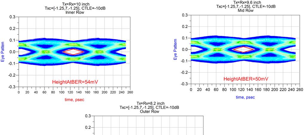

55 The Performance
56 References MQF Intel Corporation, Intel Connector Model, Quality Assessment Methodology, September andtechnology/intel connector model paper.html FSV Universitat Politecnica De Catalunya, FSV downloadable code A.P. Duffy, A.J.M. Martin, A Orlandi, G Antonini, T.M. Benson, M.S. Woolfson, "Feature Selective Validation (FSV) for validation of computational electromagnetics (CEM). Part I The FSV method", IEEE Trans. on Electromagn. Compatibility, Vol 48, No 3, Aug 2006, pp
57 Conclusion Measured and modeled connector models can have a high degree of correlation provided test fixture artifacts are properly accounted for We introduced two different metrics for model correlation: MQF Model Quality Factor FSV Feature Selective Validation Samtec has developed a PCIe Gen 3 analysis suite with ADS Includes FIR, CTLE and DFE equalization as per PCIe Gen 3 Batch simulation and parameter sweeps are used to select the optimum equalization settings Tx and Rx effects (jitter, package parasitics) are included in the suite


58
Connector Models Are They Any Good?
 Connector Models Are They Any Good? Jim Nadolny, Leon Wu Samtec Tuesday, January 31, 2012 Some Brief Housekeeping Notes: Track 14, RF/Microwave Techniques for Signal Integrity Ballroom G, Santa Clara Convention
Connector Models Are they any good?
 DesignCon 2012 Connector Models Are they any good? Jim Nadolny, Samtec jim.nadolny@samtec.com Leon Wu, Samtec leon.wu@samtec.com Abstract Channel simulations are only as accurate as the models used to
SEAM-RA/SEAF-RA Series Final Inch Designs in PCI Express Applications Generation GT/s
 SEAM-RA/SEAF-RA Series Final Inch Designs in PCI Express Applications Generation 3-8.0 GT/s Copyrights and Trademarks Copyright 2011 Samtec, Inc. Developed in conjunction with Teraspeed Consulting Group
Application Note. PCIE-RA Series Final Inch Designs in PCI Express Applications Generation GT/s
 PCIE-RA Series Final Inch Designs in PCI Express Applications Generation 3-8.0 GT/s Copyrights and Trademarks Copyright 2012, Inc. COPYRIGHTS, TRADEMARKS, and PATENTS Final Inch is a trademark of, Inc.
PCIEC PCI Express Jumper High Speed Designs in PCI Express Applications Generation GT/s
 PCIEC PCI Express Jumper High Speed Designs in PCI Express Applications Generation 3-8.0 GT/s Mated with PCIE-RA Series PCB Connectors Copyrights and Trademarks Copyright 2015, Inc. COPYRIGHTS, TRADEMARKS,
Application Note. PCIE-EM Series Final Inch Designs in PCI Express Applications Generation GT/s
 PCIE-EM Series Final Inch Designs in PCI Express Applications Generation 3-8.0 GT/s Copyrights and Trademarks Copyright 2015, Inc. COPYRIGHTS, TRADEMARKS, and PATENTS Final Inch is a trademark of, Inc.
PCI Express Gen 4 & Gen 5 Card Edge Connectors
 PCI Express Gen 4 & Gen 5 Card Edge Connectors Product Presentation Amphenol Information Communications ava and Commercial Products Agenda 1. Value Proposition 2. Product Overview 3. Signal Integrity Performance
GT Micro D High Speed Characterization Report For Differential Data Applications. Micro-D High Speed Characterization Report
 GT-14-19 Micro D For Differential Data Applications GMR7580-9S1BXX PCB Mount MWDM2L-9P-XXX-XX Cable Mount Revision History Rev Date Approved Description A 4/10/2014 C. Parsons/D. Armani Initial Release
High Speed Characterization Report. DVI-29-x-x-x-xx Mated With DVI Cable
 High Speed Characterization Report DVI-29-x-x-x-xx Mated With DVI Cable REVISION DATE: 07-18-2004 TABLE OF CONTENTS Introduction... 1 Product Description... 1 Overview... 2 Results Summary... 3 Time Domain
Board Design Guidelines for PCI Express Architecture
 Board Design Guidelines for PCI Express Architecture Cliff Lee Staff Engineer Intel Corporation Member, PCI Express Electrical and Card WGs The facts, techniques and applications presented by the following
Understanding 3M Ultra Hard Metric (UHM) Connectors
 Connectors") 3M Electronic Solutions Division 3MUHMWEBID_100809 Understanding 3M Ultra Hard Metric (UHM) Connectors Enabling performance of next generation 2 mm Hard Metric systems 3M Electronic Solutions Division
3M Electronic Solutions Division 3MUHMWEBID_100809 Understanding 3M Ultra Hard Metric (UHM) Connectors Enabling performance of next generation 2 mm Hard Metric systems 3M Electronic Solutions Division
Keysight MOI for USB Type-C Cable Assemblies Compliance Tests Using Keysight M937XA Multiport PXIe VNA
 Revision 1.01 Feb-24, 2017 Universal Serial Bus Type-C TM Specification Revision 1.1 Keysight Method of Implementation (MOI) for USB Type-C TM Cables Assemblies Compliance Tests Using Keysight For Type-C
Workshop 3-1: Coax-Microstrip Transition
 Workshop 3-1: Coax-Microstrip Transition 2015.0 Release Introduction to ANSYS HFSS 1 2015 ANSYS, Inc. Example Coax to Microstrip Transition Analysis of a Microstrip Transmission Line with SMA Edge Connector
PCI Express Electrical Basics
 PCI Express Electrical Basics Dean Gonzales Advanced Micro Devices Copyright 2015, PCI-SIG, All Rights Reserved 1 Topics PCI Express Overview Enhancements for 8GT/s Target Channels for the Specification
Advances in Measurement Based Transient Simulation
 Time Domain Simulation in ADS, Slide - 1 Advances in Measurement Based Transient Simulation Presented by GigaTest Labs Gary Otonari and Orlando Bell March, 2008 1 Time Domain Simulation in ADS, Slide -
A simple method to characterize and accurately remove the effects of push-on connectors. O.J. Danzy Application Engineer
 A simple method to characterize and accurately remove the effects of push-on connectors. O.J. Danzy Application Engineer Original Authors Robert Schaefer, Keysight Technologies, Inc. Reiner Oppelt, Rosenberger
Thank you for downloading this product training module produced by 3M Electronic Solutions Division for Mouser. In this presentation, we will discuss
 1 Thank you for downloading this product training module produced by 3M Electronic Solutions Division for Mouser. In this presentation, we will discuss a new 2mm hard metric connector that has been designed
CEI-28G-VSR Channel Simulations, Validation, & Next Steps. Nathan Tracy and Mike Fogg May 18, 2010
 CEI-28G-VSR Channel Simulations, Validation, & Next Steps Nathan Tracy and Mike Fogg May 18, 21 Summary of Contribution Updated information showing Tyco Electronics 25/28Gbps first generation modular interconnect
DensiShield Cable Assembly. InfiniBand Standard CX4 Standard
 DensiShield Cable Assembly InfiniBand Standard CX4 Standard SI-2008-06-001 Revision 1 August-21-2008 Introduction The purpose of these tests was to show compliance of FCI s 26 AWG DensiShield cable assemblies
Agilent USB3, Slide - 1. Agilent. USB3 Test Fixture Characterization. 10 MHz to 20 GHz March 12,
 Agilent USB, Slide 1 Agilent USB Test Fixture Characterization 10 MHz to 20 GHz March 12, 2009 Agilent USB, Slide 2 Measurement Summary A prototype Agilent USB test fixture was measured using a 4port PNA,
Q2 QMS/QFS 16mm Stack Height Final Inch Designs In PCI Express Applications Generation Gbps. Revision Date: February 13, 2009
 Q2 QMS/QFS 16mm Stack Height Final Inch Designs In PCI Express Applications Generation 2 5.0 Gbps Revision Date: February 13, 2009 Copyrights and Trademarks Copyright 2009 Samtec, Inc. Developed in conjunction
EXAMINING THE IMPACT OF SPLIT PLANES ON SIGNAL AND POWER INTEGRITY
 EXAMINING THE IMPACT OF SPLIT PLANES ON SIGNAL AND POWER INTEGRITY Jason R. Miller, Gustavo J. Blando, Roger Dame, K. Barry A. Williams and Istvan Novak Sun Microsystems, Burlington, MA 1 AGENDA Introduction
SAS-2 Zero-Length Test Load Characterization (07-013r7) Barry Olawsky Hewlett Packard (8/2/2007)
 Barry Olawsky Hewlett Packard (8/2/2007)") SAS-2 Zero-Length Test Load Characterization (07-013r7) Barry Olawsky Hewlett Packard (8/2/2007) 07-013r7 SAS-2 Zero-Length Test Load Characterization 1 Zero-Length Test Load Provides ideal connection
SAS-2 Zero-Length Test Load Characterization (07-013r7) Barry Olawsky Hewlett Packard (8/2/2007) 07-013r7 SAS-2 Zero-Length Test Load Characterization 1 Zero-Length Test Load Provides ideal connection
An Innovative Simulation Workflow for Debugging High-Speed Digital Designs using Jitter Separation
 An Innovative Simulation Workflow for Debugging High-Speed Digital Designs using Jitter Separation C. Chastang, A. Amédéo V. Poisson, P. Grison, F. Demuynck C. Gautier, F. Costa Thales Communications &
MECT Series Final Inch Designs in SFP+ Applications. Revision Date: August 20, 2009
 MECT Series Final Inch Designs in SFP+ Applications Revision Date: August 20, 2009 Copyrights and Trademarks Copyright 2009 Samtec, Inc. Developed in conjunction with Teraspeed Consulting Group LLC COPYRIGHTS,
MDI for 4x25G Copper and Fiber Optic IO. Quadra (CFP4 proposal) Connector System
 Connector System") MDI for 4x25G Copper and Fiber Optic IO Quadra (CFP4 proposal) Connector System Nov 7, 2011 Nathan Tracy, TE Connectivity Tom Palkert, Molex 4x25Gb/s MDI Potential Requirements Critical Needs: Excellent
MDI for 4x25G Copper and Fiber Optic IO Quadra (CFP4 proposal) Connector System Nov 7, 2011 Nathan Tracy, TE Connectivity Tom Palkert, Molex 4x25Gb/s MDI Potential Requirements Critical Needs: Excellent
EDA365. DesignCon Impact of Backplane Connector Pin Field on Trace Impedance and Vertical Field Crosstalk
 DesignCon 2007 Impact of Backplane Connector Pin Field on Trace Impedance and Vertical Field Crosstalk Ravi Kollipara, Rambus, Inc. ravik@rambus.com, (650) 947-5298 Ben Chia, Rambus, Inc. Dan Oh, Rambus,
EDGE CARD APPLICATION DESIGN GUIDE
 EDGE CARD APPLICATION DESIGN GUIDE EDGE CARD SOLUTIONS Samtec offers a full line of edge card connectivity solutions for industries and applications including datacom, industrial, high-performance computing,
RClamp0522P RClamp0524P
 PROTECTION PRODUCTS - RailClamp Description RailClamps are ultra low capacitance TVS arrays designed to protect high speed data interfaces. This series has been specifically designed to protect sensitive
SPICE Model Validation Report
 EQCD (DV to DV) Cable Assembly Mated with: QTE-xxx-01-x-D-A QSE-xxx-01-x-D-A Description: Cable Assembly, High Data Rate, 0.8mm Pitch Samtec, Inc. 2005 All Rights Reserved TABLE OF CONTENTS INTRODUCTION...
DisplayPort 1.4 Webinar
 DisplayPort 1.4 Webinar Test Challenges and Solution Yogesh Pai Product Manager - Tektronix 1 Agenda DisplayPort Basics Transmitter Testing Challenges DisplayPort Type-C Updates Receiver Testing Q and
Successfully negotiating the PCI EXPRESS 2.0 Super Highway Towards Full Compliance
 the PCI EXPRESS 2.0 Super Highway Towards Full Compliance Page 1 Agenda Introduction PCIe 2.0 changes from 1.0a/1.1 Spec 5GT/s Challenges Error Correction Techniques Test tool and fixture changes Agilent
Agilent Technologies Advanced Signal Integrity
 Agilent Technologies Advanced Signal Integrity Measurements for Next Generation High Speed Serial Standards Last Update 2012/04/24 (YS) Appendix VNA or TDR Scope? ENA Option TDR Overview USB 3.0 Cable/Connector
RiseUp RU8-DP-DV Series 19mm Stack Height Final Inch Designs in PCI Express Applications. Revision Date: March 18, 2005
 RiseUp RU8-DP-DV Series 19mm Stack Height Final Inch Designs in PCI Express Applications Revision Date: March 18, 2005 Copyrights and Trademarks Copyright 2005 Samtec, Inc. Developed in conjunction with
PDS: Rev :A STATUS:Released Printed: Jan 04, 2012
 of 2 A.0 Objective This specification defines the performance, test, quality and reliability requirements of the USB3.0 Standard- A Receptacle. 2.0 Scope This specification is applicable to the termination
I N T E R C O N N E C T A P P L I C A T I O N N O T E. STEP-Z Connector Routing. Report # 26GC001-1 February 20, 2006 v1.0
 I N T E R C O N N E C T A P P L I C A T I O N N O T E STEP-Z Connector Routing Report # 26GC001-1 February 20, 2006 v1.0 STEP-Z CONNECTOR FAMILY Copyright 2006 Tyco Electronics Corporation, Harrisburg,
QPairs QTE/QSE-DP Multi-connector Stack Designs In PCI Express Applications 16 mm Connector Stack Height REVISION DATE: OCTOBER 13, 2004
 Application Note QPairs QTE/QSE-DP Multi-connector Stack Designs In PCI Express Applications 16 mm Connector Stack Height REVISION DATE: OCTOBER 13, 2004 Copyrights and Trademarks Copyright 2004 Samtec,
Q Pairs QTE/QSE-DP Final Inch Designs In PCI Express Applications 16 mm Stack Height
 Application Note Q Pairs QTE/QSE-DP Final Inch Designs In PCI Express Applications 16 mm Stack Height Copyrights and Trademarks Copyright 2004 Samtec, Inc. Developed in conjunction with Teraspeed Consulting
Integrating ADS into a High Speed Package Design Process
 Integrating ADS into a High Speed Package Design Process Page 1 Group/Presentation Title Agilent Restricted Month ##, 200X Agenda High Speed SERDES Package Design Requirements Performance Factor and Design
High Speed and High Power Connector Design
 High Speed and High Power Connector Design Taiwan User Conference 2014 Introduction High speed connector: Electrically small Using differential signaling Data rate >100Mbps High power connector: Static
Practical Implementation of a Sequential Sampling Algorithm for EMI Near-Field Scanning
 Practical Implementation of a Sequential Sampling Algorithm for EMI Near-Field Scanning Bram Van der Streeck, Filip Vanhee, Bart Boesman, Davy Pissoort Flanders Mechatronics Engineering Center KHBO K.U.
Agenda TDR Measurements Using Real World Products
 Agenda TDR Measurements Using Real World Products The Case for using both TDR and S-parameters Device Package Analysis - Measure Impedance -C-self Characterizing Device Evaluation Test board Measure Differential
DesignCon 2005 Track 5: Chip and Board Interconnect Design (5-TA2)
") DesignCon 2005 Track 5: Chip and Board Interconnect Design (5-TA2) Connector-Less Probing: Electrical and Mechanical Advantages Authors/Presenters: Brock LaMeres, Agilent Technologies Brent Holcombe, Agilent
DesignCon 2005 Track 5: Chip and Board Interconnect Design (5-TA2) Connector-Less Probing: Electrical and Mechanical Advantages Authors/Presenters: Brock LaMeres, Agilent Technologies Brent Holcombe, Agilent
EXAMAX HIGH SPEED BACKPLANE CONNECTOR SYSTEM Innovative pinless connector system delivering superior electrical performance at speeds 25 to 56Gb/s
 EXAMAX HIGH SPEED BACKPLANE Innovative pinless connector system delivering superior electrical performance at speeds 5 to 5Gb/s SUPPORTS MANY INDUSTRY STANDARD SPECIFICATIONS; MIGRATION PATH TO HIGHER
ADS USB 3.1 Compliance Test Bench
 ADS 2016.01 USB 3.1 Compliance Test Bench Notices Keysight Technologies, Inc. 1983-2016 1400 Fountaingrove Pkwy., Santa Rosa, CA 95403-1738, United States All rights reserved. No part of this documentation
SFC ChipClamp ΤΜ Flip Chip TVS Diode with T-Filter PRELIMINARY Features
 Description The SFC2282-50 is a low pass T-filter with integrated TVS diodes. It is designed to provide bidirectional filtering of EMI/RFI signals and electrostatic discharge (ESD) protection in portable
Lecture 2: Introduction
 Lecture 2: Introduction v2015.0 Release ANSYS HFSS for Antenna Design 1 2015 ANSYS, Inc. Multiple Advanced Techniques Allow HFSS to Excel at a Wide Variety of Applications Platform Integration and RCS
Interconnect Impedance Measurements, Signal Integrity Modeling, Model Validation, and Failure Analysis. IConnect TDR Software.
 Rev. 8/27/21 Interconnect Impedance Measurements, Signal Integrity Modeling, Model Validation, and Failure Analysis IConnect TDR Software TDA Systems, Inc. www.tdasystems.com Outline TDR Impedance Measurements
AirMax VSe High Speed Backplane Connector System
 AirMax VSe High Speed Backplane Connector System July 2012 FCI Customer Presentation For External Use Where will AirMax VSe connectors be used & Why? More bandwidth density is being demanded from equipment
19. VITA 57.1 FMC HPC Connector
 Table 1-27: Switch S2 Configuration Details Switch Configuration Mode/Method Switch Net Name JTAG System ACE CF Slave SelectMAP Platform Flash XL Master BPI P30 Linear Flash S2.1 CCLK_EXTERNAL Off On Off
Hybrid Couplers 3dB, 90º Type PC2025A2100AT00
 GENERAL DESCRIPTION The PC2025A2100AT00 is a RoHS compliant low profile wideband 3dB hybrid coupler which can support mobile applications, including PCS and DCS applications. The power coupler series of
A Proposed Set of Specific Standard EMC Problems To Help Engineers Evaluate EMC Modeling Tools
 A Proposed Set of Specific Standard EMC Problems To Help Engineers Evaluate EMC Modeling Tools Bruce Archambeault, Ph. D Satish Pratapneni, Ph.D. David C. Wittwer, Ph. D Lauren Zhang, Ph.D. Juan Chen,
I N T E R C O N N E C T A P P L I C A T I O N N O T E. STRADA Whisper 4.5mm Connector Enhanced Backplane and Daughtercard Footprint Routing Guide
 I N T E R C O N N E C T A P P L I C A T I O N N O T E STRADA Whisper 4.5mm Connector Enhanced Backplane and Daughtercard Footprint Routing Guide Report # 32GC001 01/26/2015 Rev 3.0 STRADA Whisper Connector
A novel method to reduce differential crosstalk in a highspeed
 DesignCon 5 A novel method to reduce differential crosstalk in a highspeed channel Kunia Aihara, Hirose Electric kaihara@hirose.com Jeremy Buan, Hirose Electric jbuan@hirose.com Adam Nagao, Hirose Electric
RF Characterization Report
 RF058 Series Cable Assemblies RF058-01BJ1-01BJ1-0150 RF058-01SB1-01SB1-0150 RF058-01SP1-01SP1-0150 Description: RF Cable Assembly, 50Ohm, RG058 Coaxial Cable Samtec Inc. WWW.SAMTEC.COM Phone: 812-944-6733
A Modular Platform for Accurate Multi- Gigabit Serial Channel Validation
 A Modular Platform for Accurate Multi- Gigabit Serial Channel Validation Presenter: Andrew Byers Ansoft Corporation High Performance Electronics: Technical Challenges Faster data rates in increasingly
RClamp0524PA RClamp0522P
 PROTECTION PRODUCTS - RailClamp Description RailClamp TVS arrays are ultra low capacitance ESD protection devices designed to protect high speed data interfaces. This series has been specifically designed
PCI Express 3.0 Characterization, Compliance, and Debug for Signal Integrity Engineers
 PCI Express 3.0 Characterization, Compliance, and Debug for Signal Integrity Engineers - Transmitter Testing - Receiver Testing - Link Equalization Testing David Li Product Marketing Manager High Speed
Bergstak 0.80mm Pitch Product Presentation
 Bergstak 0.80mm Pitch Product Presentation Basics Portfolio Agenda 1. Value Proposition 2. Product Overview 3. Product Specifications 4. Features & Benefits 5. Markets & Applications 6. Marcomm Collaterals
Type-C Technologies and Solutions
 Type-C Technologies and Solutions 2016.12.20 Gary Hsiao Project Manager Gary_Hsiao@keysight.com Agenda Type-C Overview Type-C PD Solutions USB 3.1 Simulation Solutions USB 3.1 TX/RX Solutions USB 3.1 Cable/Connector
PCIe Electromechanical Updates Yun Ling Intel Corporation
 PCIe Electromechanical Updates Yun Ling Intel Corporation * Third party marks and brands are the property of their respective owners. Agenda 225/300 Watt High Power CEM Spec Overview System Volumetric
Designing the Right Ethernet Interconnect to Increase High-Speed Data Transmission in Military Aircraft. White Paper
 Designing the Right Ethernet Interconnect to Increase High-Speed Data Transmission in Military Aircraft White Paper May 216 Abstract: Designing the right high-speed Interconnect that enables systems to
Revolutionary High Performance Interconnect Which Maximizes Signal Density
 Revolutionary High Performance Interconnect Which Maximizes Signal Density Tom Cohen and Gautam Patel Teradyne Connection Systems 44 Simon St. Nashua, New Hampshire 03060 Phone: 603-791-3383, 603-791-3164
Modeling of Connector to PCB Interfaces. CST User Group Meeting, September 14, 2007 Thomas Gneiting, AdMOS GmbH
 Modeling of Connector to PCB Interfaces CST User Group Meeting, September 14, 2007 Thomas Gneiting, AdMOS GmbH thomas.gneiting@admos.de Table of Content Introduction Parametric CST model of connector to
PCI Express 4.0. Electrical compliance test overview
 PCI Express 4.0 Electrical compliance test overview Agenda PCI Express 4.0 electrical compliance test overview Required test equipment Test procedures: Q&A Transmitter Electrical testing Transmitter Link
Fast Electromagnetic Modeling of 3D Interconnects on Chip-package-board
 PIERS ONLINE, VOL. 6, NO. 7, 2010 674 Fast Electromagnetic Modeling of 3D Interconnects on Chip-package-board Boping Wu 1, Xin Chang 1, Leung Tsang 1, and Tingting Mo 2 1 Department of Electrical Engineering,
Product Specification
 SLH Series Socket, Vertical Orientation TLH Series Terminal, Vertical Orientation See www.samtec.com for more information. Page 1 1.0 SCOPE 1.1 This specification covers performance, testing and quality
Additional Trace Losses due to Glass- Weave Periodic Loading. Jason R. Miller, Gustavo Blando and Istvan Novak Sun Microsystems
 Additional Trace Losses due to Glass- Weave Periodic Loading Jason R. Miller, Gustavo Blando and Istvan Novak Sun Microsystems 1 Introduction PCB laminates are composed of resin and a glass fabric Two
Lecture 10. Vector Network Analyzers and Signal Flow Graphs
 HP8510 Lecture 10 Vector Network Analyzers and Signal Flow Graphs Sections: 6.7 and 6.11 Homework: From Section 6.13 Exercises: 4, 5, 6, 7, 9, 10, 22 Acknowledgement: Some diagrams and photos are from
Crosstalk Measurements for Signal Integrity Applications. Chris Scholz, Ph.D. VNA Product Manager R&S North America
 Crosstalk Measurements for Signal Integrity Applications Chris Scholz, Ph.D. VNA Product Manager R&S North America Outline ı A brief history of crosstalk ı Introduction to crosstalk Definition of crosstalk
I N T E R C O N N E C T A P P L I C A T I O N N O T E. Z-PACK TinMan Connector Routing. Report # 27GC001-1 May 9 th, 2007 v1.0
 I N T E R C O N N E C T A P P L I C A T I O N N O T E Z-PACK TinMan Connector Routing Report # 27GC001-1 May 9 th, 2007 v1.0 Z-PACK TinMan Connectors Copyright 2007 Tyco Electronics Corporation, Harrisburg,
Agilent Bead Probe Technology
 Agilent Bead Probe Technology Page 1 Abstract Lead-free, shrinking geometries, new packages and high-speed signaling present new challenges for ICT. The impact will be more defects, loss of access, lower
for Summit Analyzers Installation and Usage Manual
 Protocol Solutions Group PCI Express 2.0 Mid-Bus Probe for Summit Analyzers Installation and Usage Manual Manual Version 1.1 Generated on: 2/7/2018 6:25 PM Document Disclaimer The information contained
APPLICATION SPECIFICATION. 1 of 33 J (r/a header, r/a receptacle, vertical header, vertical receptacle TABLE OF CONTENTS 1. OBJECTIVE...
 1 of 33 J Section TABLE OF CONTENTS page no. 1. OBJECTIVE...2 2. SCOPE...2 3. APPLICABLE DOCUMENTS...3 4. GENERAL CUSTOMER INFORMATION...3 4.1. CONNECTOR CONFIGURATIONS...3 4.2. COMPATIBILITY WITH HARD
Package on Board Simulation with 3-D Electromagnetic Simulation
 White Paper Package on Board Simulation with 3-D Electromagnetic Simulation For many years, designers have taken into account the effect of package parasitics in simulation, from using simple first-order
RClamp TM 0504M RailClamp Low Capacitance TVS Diode Array PRELIMINARY Features
 Description RailClamps are surge rated diode arrays designed to protect high speed data interfaces. The RClamp series has been specifically designed to protect sensitive components which are connected
5 GT/s and 8 GT/s PCIe Compared
 5 GT/s and 8 GT/s PCIe Compared Bent Hessen-Schmidt SyntheSys Research, Inc. Copyright 2008, PCI-SIG, All Rights Reserved 1 Disclaimer The material included in this presentation reflects current thinking
Channels for Consideration by the Signaling Ad Hoc
 Channels for Consideration by the Signaling Ad Hoc John D Ambrosia Tyco Electronics Adam Healey, Agere Systems IEEE P802.3ap Signaling Ad Hoc September 17, 2004 Two-Connector Topology N2 H B September,
Powerful features (1)
") HFSS Overview Powerful features (1) Tangential Vector Finite Elements Provides only correct physical solutions with no spurious modes Transfinite Element Method Adaptive Meshing r E = t E γ i i ( x, y,
HFSS Overview Powerful features (1) Tangential Vector Finite Elements Provides only correct physical solutions with no spurious modes Transfinite Element Method Adaptive Meshing r E = t E γ i i ( x, y,
PI2EQX6804-ANJE Four-lane SAS/SATA ReDriver Application Information May 13, 2011
 Contents General Introduction How to use pin strap and I2C control External Components Requirement Layout Design Guide Power Supply Bypassing Power Supply Sequencing Equalization Setting Output Swing Setting
802.3cb PMD and Channel. Anthony Calbone 3/14/2016
 802.3cb PMD and Channel Anthony Calbone 3/14/2016 Overview The presentation introduces a single link segment for each 2.5 Gb/s and 5 Gb/s for 802.3cb This link segment is described for two different reference
3M TM VCP TM Package Stripline Two Port Characterization. David A. Hanson Division Scientist 3M Microelectronic Packaging
 3M TM VCP TM Package Stripline Two Port Characterization David A. Hanson Division Scientist 3M Microelectronic Packaging 3M 21 2 Background To support the requirements of 2.5GBs and 1GBs data communication
PCI Express 3.0 Testing Approaches for PHY and Protocol Layers
 PCI Express 3.0 Testing Approaches for PHY and Protocol Layers Agenda Introduction to PCI Express 3.0 Trends and Challenges Physical Layer Testing Overview Transmitter Design & Validation Transmitter Compliance
XPort Direct+ NC Addendum
 XPort Direct+ NC Addendum Part No. 900-535 Rev. A February 2008 Contents Overview 3 PCB Interface Signals 3 Connecting XPort Direct+ NC to an Ethernet Port 4 Selecting LAN Magnetics 4 Common-Mode Choke
Keysight MOI for USB 2.0 Connectors & Cable Assemblies Compliance Tests
 Revision 1.10 October 18, 2016 Universal Serial Bus Specification Revision 2.0 Keysight Method of Implementation (MOI) for USB 2.0 Connectors and Cables Assemblies Compliance Tests Using Keysight E5071C
Optimum Placement of Decoupling Capacitors on Packages and Printed Circuit Boards Under the Guidance of Electromagnetic Field Simulation
 Optimum Placement of Decoupling Capacitors on Packages and Printed Circuit Boards Under the Guidance of Electromagnetic Field Simulation Yuzhe Chen, Zhaoqing Chen and Jiayuan Fang Department of Electrical
Differential Return Loss for Annex 120d Addressing to Comments i-34, i-74, i-75
 Differential Return Loss for Annex 120d Addressing to Comments i-34, i-74, i-75 Richard Mellitz, Samtec Adee Ran, Intel March 2017 IEEE802.3 Plenary, Vancouver, BC, Canada 1 IEEE P802.3bs 200 Gb/s and
Open NAND Flash Interface Specification: NAND Connector
 Open NAND Flash Interface Specification: NAND Connector Connector Revision 1.0 23-April-2008 Hynix Semiconductor Intel Corporation Micron Technology, Inc. Phison Electronics Corp. Sony Corporation Spansion
I N T E R C O N N E C T A P P L I C A T I O N N O T E. Advanced Mezzanine Card (AMC) Connector Routing. Report # 26GC011-1 September 21 st, 2006 v1.
 Connector Routing. Report # 26GC011-1 September 21 st, 2006 v1.") I N T E R C O N N E C T A P P L I C A T I O N N O T E Advanced Mezzanine Card (AMC) Connector Routing Report # 26GC011-1 September 21 st, 2006 v1.0 Advanced Mezzanine Card (AMC) Connector Copyright 2006
I N T E R C O N N E C T A P P L I C A T I O N N O T E Advanced Mezzanine Card (AMC) Connector Routing Report # 26GC011-1 September 21 st, 2006 v1.0 Advanced Mezzanine Card (AMC) Connector Copyright 2006
100BASE-T1 EMC Test Specification for ESD suppression devices
 IEEE 100BASE-T1 EMC Test Specification for ESD suppression devices Version 1.0 Author & Company Dr. Bernd Körber, FTZ Zwickau Title 100BASE-T1 EMC Test Specification for ESD suppression devices Version
Board Mount Connector Footprint Design Process
 Board Mount Connector Footprint Design Process STEP 1: Connector Selection Series Force to Engage (Max) Max SB LD FD Freq. SMP 2.0 lbs 10 lbs 15 lbs 40 GHz SMPM 3.5 lbs N/A 8.0 lbs 65 GHz SMPS 3.0 lbs
DesignCon Impact of Probe Coupling on the Accuracy of Differential VNA Measurements
 DesignCon 2013 Impact of Probe Coupling on the Accuracy of Differential VNA Measurements Sarah Paydavosi, Oracle Corp. Laura Kocubinski, Oracle Corp. Jason Miller, Oracle Corp. Gustavo Blando, Oracle Corp.
RClamp0502B. Ultra-Low Capacitance TVS for ESD and CDE Protection. PROTECTION PRODUCTS - RailClamp Description. Features. Mechanical Characteristics
 - RailClamp Description RailClamps are ultra low capacitance TS arrays designed to protect high speed data interfaces. This series has been specifically designed to protect sensitive components which are
ExaMAX HIGH-SPEED BACKPLANE SYSTEMS
 ExaMX HIGH-SPEE CKPLNE SYSTEMS ExaMX HIGH-SPEE CKPLNE SYSTEMS ExaMX high-speed backplane systems deliver 28 Gbps of electrical performance while offering an easy migration path to 56 Gbps. choice of 28
PCI Express 1.0a and 1.1 Add-In Card Transmitter Testing
 Abstract PCI Express 1.0a and 1.1 Add-In Card Transmitter Testing Joan Gibson November 2006 SR-TN062 Add-in cards designed for PCI Express require numerous tests to assure inter-operability with different
White Paper. Lightweight Connectors for Demanding Applications. June by Brad Taras Product Manager Cinch Connectivity Solutions
 White Paper Lightweight Connectors for Demanding Applications June 2018 by Brad Taras Product Manager Cinch Connectivity Solutions Phenomenal levels of integration are being achieved in modern electronics
What s New in HyperLynx 8.0
 What s New in HyperLynx 8.0 Copyright Mentor Graphics Corporation 2009 All Rights Reserved. Mentor Graphics, Board Station XE Flow, ViewDraw, Falcon Framework, IdeaStation, ICX and Tau are registered trademarks
Impact of Embedded Capacitance on Test Socket and Test Board Performance Michael Giesler, 3M, Alexander Barr, 3M Yoshihisa Kawate,
 Impact of Embedded Capacitance on Test Socket and Test Board Performance Michael Giesler, 3M, msgiesler@mmm.com Alexander Barr, 3M Yoshihisa Kawate, Sumitomo-3M Yuichi Tsubaki, Sumitomo-3M Silicon Valley
ELECTRICAL SPECIFICATIONS**
 REV A Hybrid Couplers 3 db, 90 Description The 1P503AS Pico Xinger is a low profile, high performance 3dB hybrid coupler in an easy to use manufacturing friendly surface mount package. It is designed for
SAS-2 Internal Channel Modeling (05-276r0) Barry Olawsky Hewlett Packard r0 SAS-2 Channel Modeling 1
 Barry Olawsky Hewlett Packard r0 SAS-2 Channel Modeling 1") SAS-2 Internal Channel Modeling (05-276r0) Barry Olawsky Hewlett Packard 05-276r0 SAS-2 Channel Modeling 1 Project Goals Provide industry with data to better understand customer (hp and other OEMs) applications.
SAS-2 Internal Channel Modeling (05-276r0) Barry Olawsky Hewlett Packard 05-276r0 SAS-2 Channel Modeling 1 Project Goals Provide industry with data to better understand customer (hp and other OEMs) applications.