CMOS VLSI DESIGN ROCHESTER INSTITUTE OF TECHNOLOGY MICROELECTRONIC ENGINEERING CMOS VLSI DESIGN. Dr. Lynn Fuller
|
|
|
- Caroline Ferguson
- 6 years ago
- Views:
Transcription
1 ROCHESTER INSTITUTE OF TECHNOLOGY MICROELECTRONIC ENGINEERING CMOS VLSI DESIGN Dr. Lynn Fuller Webpage: 82 Lomb Memorial Drive Rochester, NY Tel (585) Fax (585) Department webpage: cmosvlsi2011.ppt Page 1
2 OUTLINE Design Approach Process Technology MOSIS Design Rules Primitive Cells, Basic Cells, Macro Cells Projects Maskmaking References Homework Page 2

3 THE NEED FOR CAD With millions of transistors per chip it is impossible to design with no errors without computers to check layout, circuit performance, process design, etc. Page 3


4 COMPARISON OF DESIGN METHODOLOGIES Full Custom Design Direct control of layout and device parameters Longer design time but faster operation more dense Standard Cell Design Easier to implement Limited cell library selections Gate Array or Programmable Logic Array Design Fastest design turn around Reduced Performance Page 4
5 STAGES IN THE CAD PROCESS Problem Specification Behavioral Design Functional and Logic Design Circuit Design Physical Design (Layout) Fabrication Technology CAD (TCAD) Packaging Testing Page 5
6 DESIGN HEIRARCHY - LEVELS OF ABSTRACTION A = B + C if (A) then X: = Y Behavioral Model ALU RAM Block-Functional Model Gate-Level Model Transistor level Model Geometric Model Page 6
7 PROCESS SELECTION It is not necessary to know all process details to do CMOS integrated circuit design. However the process determines important circuit parameters such as supply voltage and maximum frequency of operation. It also determines if devices other than PMOS and NMOS transistors can be realized such as poly-to-poly capacitors and EEPROM transistors. The number of metal interconnect layers is also part of the process definition. Page 7
8 RIT SUBµ CMOS RIT Subµ CMOS 150 mm wafers Nsub = 1E15 cm-3 Nn-well = 3E16 cm-3 Xj = 2.5 µm Np-well = 1E16 cm-3 Xj = 3.0 µm LOCOS Field Ox = 6000 Å Xox = 150 Å Lmin= 1.0 µm LDD/Side Wall Spacers 2 Layers Aluminum L Long Channel Behavior 3.3 Volt Technology VT s = +/ Volt Robust Process (always works) Fully Characterized (SPICE) Page 8
9 RIT SUBµ CMOS N+ Poly NMOSFET PMOSFET p+ well contact 5000 Å Field Oxide N+ D/S LDD LDD P+ D/S n+ well contact P-well N-well Channel Stop Substrate 10 ohm-cm Page 9
10 RIT ADVANCED CMOS VER 150 RIT Advanced CMOS 150 mm Wafers Nsub = 1E15 cm-3 or 10 ohm-cm, p Nn-well = 1E17 cm-3 Xj = 2.5 µm Np-well = 1E17 cm-3 Xj = 2.5 µm Shallow Trench Isolation Field Ox (Trench Fill) = 4000 Å Dual Doped Gate n+ and p+ Xox = 100 Å Lmin = 0.5 µm, Lpoly = 0.35 µm, Leff = 0.11 µm LDD/Nitride Side Wall Spacers TiSi2 Salicide Tungsten Plugs, CMP, 2 Layers Aluminum L Long Channel Behavior Vdd = 3.3 volts Vto= volts Page 10
11 RIT ADVANCED CMOS NMOSFET N+ Poly PMOSFET P+ Poly p+ well contact N+ D/S LDD P-well N-well LDD P+ D/S n+ well contact Page 11
12 LAMBDA, Lmin, Ldrawn, Lmask, Lpoly, Lint, Leff, L Source at 0 V Ldrawn Lmask Lpoly Gate Lambda = design rule parameter, λ, ie 0.25µm Lmin = min drawn poly length, 2λ 0.50µm Lmask =? Depends on +/-bias 1.00µm x 5 Lresist after photo (resist trimming??) 0.50µm Lpoly after poly etch 0.40µm Lpoly after poly reoxidation 0.35µm Lint Leff L Drain at 3.3V Ldrawn = what was drawn 0.30µm 0.20µm 0.11µm Internal Channel Length, Lint =distance between junctions, including under diffusion Effective Channel Length, Leff = distance between space charge layers,vd = Vs= 0 Channel Length, L, = distance between space charge layers, when Vd= what it is Extracted Channel Length Parameters = anything that makes the fit good (not real) Page 12


13 MOSIS TSMC POLY 4 METAL PROCESS Page 13
14 MOSIS TSMC POLY 4-METAL LAYERS MASK LAYER NAME MENTOR NAME GDS # COMMENT N WELL N_well.i 42 ACTIVE Active.i 43 POLY Poly.i 46 N PLUS N_plus_select.i 45 P PLUS P_plus_select.i 44 CONTACT Contact.i 25 Active_contact.i 48 poly_contact.i 47 METAL1 Metal1.i 49 VIA Via.i 50 METAL2 Metal2.i 51 Page 14
15 MORE LAYERS USED IN MASK MAKING LAYER NAME GDS COMMENT cell_outline.i 70 Not used alignment 81 Placed on first level mask nw_res 82 Placed on nwell level mask active_lettering 83 Placed on active mask channel_stop 84 Overlay/Resolution for Stop Mask pmos_vt 85 Overlay/Resolution for Vt Mask LDD 86 Overlay/Resolution for LDD Masks p plus 87 Overlay/Resolution for P+ Mask n plus 88 Overlay/Resolution for N+ Mask Page 15
16 OTHER LAYERS Design Layers N-WELL (42) ACTIVE (43) POLY (46) P-SELECT (44) N-SELECT (45) CC (25) METAL 1 (49) VIA (50) METAL 2 (51) 85 Other Design Layers P+ Resolution (87) STI Resolution (82) Stop Resolution (84) Vt Resolution (85) Active Resolution (83) N+ Resolution (88) STI Nmos Vt 87 Poly Active 83 Stop P+ N+ Page 16
17 LAMBDA BASED DESIGN RULES The design rules may change from foundry to foundry or for different technologies. So to make the design rules generic the sizes, separations and overlap are given in terms of numbers of lambda (λ). The actual size is found by multiplying the number by the value for lambda for that specific foundry. For example: RIT PMOS process λ = 10 µm and minimum metal width is 3 λ so that gives a minimum metal width of 30 µm. The RIT SUB-CMOS process has λ = 0.5 µm and the minimum metal width is also 3 λ so minimum metal is 1.5 µm but if we send our CMOS designs out to industry λ might be 0.25 µm so the minimum metal of 3 λ corresponds to 0.75 µm. In all cases the design rule is the minimum metal width = 3 λ Page 17
18 LAYOUT RULES Perfect Overlay Slight Overlay Not Fatal Misalignment Fatal Layout rules prevent slight misalignment from being fatal. Page 18
19 MOSIS LAMBDA BASED DESIGN RULES Diff Potential Well active 1 Active in p-well Poly 1 3 Active 3 n+ n+ p+ Poly Same well edge Poly Potential n-substrate 5 3 (Outside well) 2 p+ n+ 3 contact to poly metal p select 2 If λ = 1 µm then contact is 2 µm x 2 µm Page 19
20 MOSIS LAMBDA BASED DESIGN RULES metal two 3 MOSIS Educational Program 4 1Instructional Processes Include: AMI λ = 0.8 µm SCMOS Rules AMI λ = 0.35 µm SCMOS Rules 1 Research Processes: go down to poly length of 65nm Page 20
21 MOSIS REQUIREMENTS MOSIS requires that projects have successfully passed LVS (Layout Versus Schematic) and DRC (Design Rule Checking). Our MENTOR tools for LVS and DRC (as they are set up) require separate N-select and P-select levels in order to know an NMOS transistor from a PMOS transistor. Although either an N-well, P-well or both will work for a twin well process, we have set up our DRC to look for N-well. Page 21
22 RIT PROCESSES At RIT we use the Sub-CMOS and ADV-CMOS processes for most designs. In these processes the minimum poly length is 1µm and 0.5µm respectively. We use scalable MOSIS design rules with lambda equal to 0.5µm and 0.25µm. These processes use one layer of poly and two layers of metal. The examples on the following pages are designs that could be made with either of the above processes. As a result the designs are generous, meaning that larger than minimum dimensions are used. For example λ = 0.5µm and minimum poly is 2λ but designed at 2.5µm because our poly etch is isotropic. The design approach for digital circuits is to design primitive cells and then use the primitive cells to design basic cells which are then used in the project designs. A layout approach is also used that allows for easy assembly of these cells into more complex cells. Page 22


23 PRIMITIVE CELLS Primitive Cells Inverter NOR2 NOR3 NOR4 NAND2 NAND3 NAND4 Etc. Page 23


24 CMOS INVERTER Vin Vout Vin +V Idd PMOS Vout NMOS CMOS TRUTH TABLE VIN VOUT W = 40 µm Ldrawn = 2.5µm Lpoly = 1.5µm Leff = 0.75 µm Page 24
25 NOR and NAND VA VB VOUT VA VB VOUT VA VB VOUT VA VB VOUT +V V VOUT VA VOUT VA VB VB Page 25
26 OTHER LOGIC GATES AND OR 3 INPUT AND 3 INPUT OR VA VB VOUT VA VB VOUT VA VB VC VOUT VA VB VC VOUT VA VB VOUT VA VB VOUT VA VB VC VOUT VA VB VC VOUT Page 26


27 MORE PRIMITIVE CELLS Page 27


28 MORE PRIMITIVE CELLS Page 28
29 BASIC CELLS Basic Cells XOR D FF JK FF Data Latch A XOR B Page 29


30 XOR Page 30

31 XOR Page 31
32 FILP-FLOPS RS FLIP FLOP R S Q QBAR R S Q 0 0 Qn INDETERMINATE D FLIP FLOP Q DATA CLOCK QBAR Q=DATA IF CLOCK IS HIGH IF CLOCK IS LOW Q=PREVIOUS DATA VALUE Page 32
33 EDGE TRIGGERED D FLIP FLOP Page 33


34 EDGE TRIGGERED D FLIP FLOP Page 34
35 T FLIP FLOP TOGGEL FLIP FLOP T Q QBAR T Qn-1 Q Q: TOGGELS HIGH AND LOW WITH EACH INPUT Page 35

36 JK FLIP FLOP Page 36
37 PROJECTS Multiplexer Full Adder Binary Counter I 0 I 1 A A A B I 0 A BI 1 Q I 2 B B AB I 2 I 3 ABI 3 4:1 Multiplexer Page 37


38 MULTIPLEXER Page 38
39 DE MULTIPLEXER De-multiplexer I A B Q 0 Q 1 Q 2 Q 3 Q 0 = A B I so that when I=0 Q 0 =0 or when I=1 Q 0 = 1 similarly for Q 1, Q 2 and Q 3 Q 1 = A BI INPUTS OUTPUTS A B Q 0 Q 1 Q 2 Q I I I I Page 39


40 DE MULTIPLEXER Page 40
41 FULL ADDER A B CIN SUM COUT COUT SU M A B Cin Page 41


42 FULL ADDER Page 42
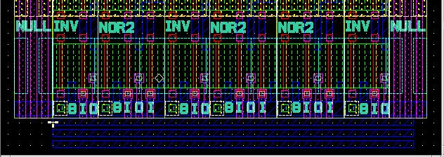
43 8-BIT BINARY COUNTER Page 43


44 8-BIT BINARY COUNTER Page 44
45 FILE FORMATS Mentor- ICGraph files (filename.iccel), all layers, polygons with up to 200 vertices GDS2- CALMA files (old IC design tool) (filename.gds), all layers, polygons MEBES- files for electron beam maskmaking tool, each file one layer, trapezoids only Page 45
46 RIT SUB-CMOS PROCESS p+ well contact N+ Poly NMOSFET 0.75 µm Aluminum 6000 Å Field Oxide N+ D/S LDD LDD P+ D/S n+ well contact Channel Stop P-well N-well PMOSFET N-type Substrate 10 ohm-cm CC POLY ACTIVE P SELECT LVL 1 n-well LVL 2 - ACTIVE LVL 3 - STOP LVL 4 - PMOS VT LVL 6 P-LDD LVL 7 N-LDD LVL 8 - P+ D/S LVL 9 - N+ D/S METAL LVL 8 - CC N SELECT N-WELL LVL 5 - POLY 11 PHOTO LEVELS LVL 9 - METAL
47 RIT ADVANCED CMOS NMOSFET N+ Poly PMOSFET P+ Poly LVL 1 - STI LVL 7 - PLDD p+ well contact P-well N+ D/S LDD N-well LDD P+ D/S n+ well contact LVL 2 - NWell LVL 8 - NLDD 12 PHOTO LEVELS + 2 FOR EACH ADDITIONAL METAL LAYER POLY LVL 3 - Pwell LVL 9 N+D/S CC ACTIVE P SELECT LVL 4 - VTP LVL 10 P+D/S METAL LVL 5 - VTN LVL 11 - CC N SELECT N-WELL LVL 6 - POLY LVL 12 METAL 1
48 OTHER MASKMAKING FEATURES Fiducial Marks-marks on the edge of the mask used to align the mask to the stepper Barcodes Titles Alignment Keys- marks on the die from a previous level used to align the wafer to the stepper CD Resolution Targets- lines and spaces Overlay Verniers- structures that allow measurement of x and y overlay accuracy Tiling Optical Proximity Correction (OPC) Page 48
49 REFERENCES 1. Silicon Processing for the VLSI Era, Volume 1 Process Technology, 2 nd, S. Wolf and R.N. Tauber, Lattice Press. 2. The Science and Engineering of Microelectronic Fabrication, Stephen A. Campbell, Oxford University Press, MOSIS Scalable CMOS Design Rules for Generic CMOS Processes, and Page 49
50 HOMEWORK - CMOS VLSI DESIGN 1. Sketch and label the seven layout layers of a CMOS 2-input OR gate that uses the MOSIS lambda based design rules and uses minimum area. Calculate the area of the smallest rectangle to enclose the design in µm What lithographic layers are not drawn by the designer in the Adv-CMOS process? How are they created? 3. For the SUB-CMOS layout shown below sketch the crossection A-A just after level 5 lithography. A 4. Does the designer put the alignment marks, fiducial marks, barcode, resolution and overlay features on the design? A Page 50
CMOS Process Flow. Layout CAD Tools
 CMOS Process Flow See supplementary power point file for animated CMOS process flow (see class ece410 website and/or* http://www.multimedia.vt.edu/ee5545/): This file should be viewed as a slide show It
Introduction to Computer Aided Design (CAD) Dr. Lynn Fuller Webpage:
 Dr. Lynn Fuller Webpage:") ROCHESTER INSTITUTE OF TECHNOLOGY MICROELECTRONIC ENGINEERING Introduction to Computer Aided Design (CAD) Dr. Lynn Fuller Webpage: http://people.rit.edu/lffeee 82 Lomb Memorial Drive Rochester, NY 14623-5604
ROCHESTER INSTITUTE OF TECHNOLOGY MICROELECTRONIC ENGINEERING Introduction to Computer Aided Design (CAD) Dr. Lynn Fuller Webpage: http://people.rit.edu/lffeee 82 Lomb Memorial Drive Rochester, NY 14623-5604
Introduction to Computer Aided Design (CAD) Dr. Lynn Fuller Webpage:
 Dr. Lynn Fuller Webpage:") ROCHESTER INSTITUTE OF TECHNOLOGY MICROELECTRONIC ENGINEERING Introduction to Computer Aided Design (CAD) Dr. Lynn Fuller Webpage: http://www.rit.edu/~lffeee 82 Lomb Memorial Drive Rochester, NY 14623-5604
ROCHESTER INSTITUTE OF TECHNOLOGY MICROELECTRONIC ENGINEERING Introduction to Computer Aided Design (CAD) Dr. Lynn Fuller Webpage: http://www.rit.edu/~lffeee 82 Lomb Memorial Drive Rochester, NY 14623-5604
Composite Layout CS/EE N-type from the top. N-type Transistor. Diffusion Mask. Polysilicon Mask
 Composite Layout CS/EE 6710 Introduction to Layout Inverter Layout Example Layout Design Rules Drawing the mask layers that will be used by the fabrication folks to make the devices Very different from
Lab. Course Goals. Topics. What is VLSI design? What is an integrated circuit? VLSI Design Cycle. VLSI Design Automation
 Course Goals Lab Understand key components in VLSI designs Become familiar with design tools (Cadence) Understand design flows Understand behavioral, structural, and physical specifications Be able to
Lecture 4a. CMOS Fabrication, Layout and Simulation. R. Saleh Dept. of ECE University of British Columbia
 Lecture 4a CMOS Fabrication, Layout and Simulation R. Saleh Dept. of ECE University of British Columbia res@ece.ubc.ca 1 Fabrication Fabrication is the process used to create devices and wires. Transistors
FABRICATION OF CMOS INTEGRATED CIRCUITS. Dr. Mohammed M. Farag
 FABRICATION OF CMOS INTEGRATED CIRCUITS Dr. Mohammed M. Farag Outline Overview of CMOS Fabrication Processes The CMOS Fabrication Process Flow Design Rules EE 432 VLSI Modeling and Design 2 CMOS Fabrication
Circuits. L3: Fabrication and Layout -1 ( ) B. Mazhari Dept. of EE, IIT Kanpur. B. Mazhari, IITK. G-Number
 B. Mazhari Dept. of EE, IIT Kanpur. B. Mazhari, IITK. G-Number") EE60: CMOS Analog Circuits L: Fabrication and Layout - (8.8.0) B. Mazhari Dept. of EE, IIT Kanpur Suppose we have a Silicon wafer which is P-type and we wish to create a region within it which is N-type
EE60: CMOS Analog Circuits L: Fabrication and Layout - (8.8.0) B. Mazhari Dept. of EE, IIT Kanpur Suppose we have a Silicon wafer which is P-type and we wish to create a region within it which is N-type
Spiral 2-8. Cell Layout
 2-8.1 Spiral 2-8 Cell Layout 2-8.2 Learning Outcomes I understand how a digital circuit is composed of layers of materials forming transistors and wires I understand how each layer is expressed as geometric
Lay ay ut Design g R ules
 HPTER 5: Layout esign Rules Introduction ny circuit physical mask layout must conform to a set of geometric constraints or rules called as Layout esign rules before it can be manufactured using particular
Process technology and introduction to physical
 Neuromorphic Engineering II Lab 3, Spring 2014 1 Lab 3 March 10, 2014 Process technology and introduction to physical layout Today you will start to learn to use the Virtuoso layout editor XL which is
EE 330 Laboratory 3 Layout, DRC, and LVS
 EE 330 Laboratory 3 Layout, DRC, and LVS Spring 2018 Contents Objective:... 2 Part 1 creating a layout... 2 1.1 Run DRC... 2 1.2 Stick Diagram to Physical Layer... 3 1.3 Bulk Connections... 3 1.4 Pins...
CMOS Inverter & Logic Lab ROCHESTER INSTITUTE OF TECHNOLOGY MICROELECTRONIC ENGINEERING. CMOS Inverter Lab
 ROCHESTER INSTITUTE OF TECHNOLOGY MICROELECTRONIC ENGINEERING CMOS Inverter Lab Dr. Lynn Fuller Webpage: http://people.rit.edu/lffeee/ 82 Lomb Memorial Drive Rochester, NY 14623-5604 Tel (585) 475-2035
Design rule illustrations for the AMI C5N process can be found at:
 Cadence Tutorial B: Layout, DRC, Extraction, and LVS Created for the MSU VLSI program by Professor A. Mason and the AMSaC lab group. Revised by C Young & Waqar A Qureshi -FS08 Document Contents Introduction
FABRICATION TECHNOLOGIES
 FABRICATION TECHNOLOGIES DSP Processor Design Approaches Full custom Standard cell** higher performance lower energy (power) lower per-part cost Gate array* FPGA* Programmable DSP Programmable general
ESE570 Spring University of Pennsylvania Department of Electrical and System Engineering Digital Integrated Cicruits AND VLSI Fundamentals
 University of Pennsylvania Department of Electrical and System Engineering Digital Integrated Cicruits AND VLSI Fundamentals ESE570, Spring 2019 HW5: Delay and Layout Sunday, February 17th Due: Friday,
Introduction 1. GENERAL TRENDS. 1. The technology scale down DEEP SUBMICRON CMOS DESIGN
 1 Introduction The evolution of integrated circuit (IC) fabrication techniques is a unique fact in the history of modern industry. The improvements in terms of speed, density and cost have kept constant
Bulk MEMS Layout 2017 Dr. Lynn Fuller, Casey Gonta, Patsy Cadareanu Webpage:
 ROCHESTER INSTITUTE OF TECHNOLOGY MICROELECTRONIC ENGINEERING Bulk MEMS Layout 2017 Dr. Lynn Fuller, Casey Gonta, Patsy Cadareanu Webpage: http://people.rit.edu/lffeee 82 Lomb Memorial Drive Rochester,
Digital Integrated Circuits A Design Perspective. Jan M. Rabaey
 Digital Integrated Circuits A Design Perspective Jan M. Rabaey Outline (approximate) Introduction and Motivation The VLSI Design Process Details of the MOS Transistor Device Fabrication Design Rules CMOS
EE 330 Laboratory 3 Layout, DRC, and LVS Fall 2015
 EE 330 Laboratory 3 Layout, DRC, and LVS Fall 2015 Contents Objective:... 2 Part 1 Creating a layout... 2 1.1 Run DRC Early and Often... 2 1.2 Create N active and connect the transistors... 3 1.3 Vias...
3. Implementing Logic in CMOS
 3. Implementing Logic in CMOS 3. Implementing Logic in CMOS Jacob Abraham Department of Electrical and Computer Engineering The University of Texas at Austin VLSI Design Fall 27 September, 27 ECE Department,
ESE 570 Cadence Lab Assignment 2: Introduction to Spectre, Manual Layout Drawing and Post Layout Simulation (PLS)
") ESE 570 Cadence Lab Assignment 2: Introduction to Spectre, Manual Layout Drawing and Post Layout Simulation (PLS) Objective Part A: To become acquainted with Spectre (or HSpice) by simulating an inverter,
ESE 570 Cadence Lab Assignment 2: Introduction to Spectre, Manual Layout Drawing and Post Layout Simulation (PLS) Objective Part A: To become acquainted with Spectre (or HSpice) by simulating an inverter,
Digital Integrated Circuits (83-313) Lecture 2: Technology and Standard Cell Layout
 Lecture 2: Technology and Standard Cell Layout") Digital Integrated Circuits (83-313) Lecture 2: Technology and Standard Cell Layout Semester B, 2016-17 Lecturer: Dr. Adam Teman TAs: Itamar Levi, Robert Giterman 26 March 2017 Disclaimer: This course
Digital Integrated Circuits (83-313) Lecture 2: Technology and Standard Cell Layout Semester B, 2016-17 Lecturer: Dr. Adam Teman TAs: Itamar Levi, Robert Giterman 26 March 2017 Disclaimer: This course
Layout and Layout Verification. of an Inverter Circuit
 Layout and Layout Verification of an Inverter Circuit Santa Clara University Department of Electrical Engineering By Piyush Panwar Under Guidance of Dr Samiha Mourad Date of Last Revision: August 7, 2010
VLSI Lab Tutorial 3. Virtuoso Layout Editing Introduction
 VLSI Lab Tutorial 3 Virtuoso Layout Editing Introduction 1.0 Introduction The purpose of this lab tutorial is to guide you through the design process in creating a custom IC layout for your CMOS inverter
Mixed-Signal&RF -0.18μm. 0.18um Process Feature. 0.18um Process Device Feature. 0.18um Process Key Design Rule. Isolation
 Mixed-Signal/RF-0.18μm CSMC 0.18 micron process is process-matched to other foundry. CSMC logic process provide generic and low power process. 0.18 micron process provide 1.8V operation voltage core device,
Chapter 6. CMOS Functional Cells
 Chapter 6 CMOS Functional Cells In the previous chapter we discussed methods of designing layout of logic gates and building blocks like transmission gates, multiplexers and tri-state inverters. In this
CMOS Design Lab Manual
 CMOS Design Lab Manual Developed By University Program Team CoreEl Technologies (I) Pvt. Ltd. 1 Objective Objective of this lab is to learn the Mentor Graphics HEP2 tools as well learn the flow of the
CPE/EE 427, CPE 527, VLSI Design I: Tutorial #1, Full Custom VLSI (inverter layout)
") CPE/EE 427, CPE 527, VLSI Design I: Tutorial #1, Full Custom VLSI (inverter layout) Joel Wilder, Aleksandar Milenkovic, ECE Dept., The University of Alabama in Huntsville Adapted from Virginia Tech, Dept.
CPE/EE 427, CPE 527, VLSI Design I: Tutorial #1, Full Custom VLSI (inverter layout) Joel Wilder, Aleksandar Milenkovic, ECE Dept., The University of Alabama in Huntsville Adapted from Virginia Tech, Dept.
Cadence Virtuoso Schematic Design and Circuit Simulation Tutorial
 Cadence Virtuoso Schematic Design and Circuit Simulation Tutorial Introduction This tutorial is an introduction to schematic capture and circuit simulation for ENGN1600 using Cadence Virtuoso. These courses
VBIT COURSE MATERIAL VLSI DESIGN
 UNIT II VLSI CIRCUIT DESIGN PROCESSES: VLSI Design Flow, MOS Layers, Stick Diagrams, Design Rules and Layout, 2μm CMOS Design rules for wires, Contacts and Transistors Layout Diagrams for NMOS and CMOS
Introduction to Semiconductor Memory Dr. Lynn Fuller Webpage:
 ROCHESTER INSTITUTE OF TECHNOLOGY MICROELECTRONIC ENGINEERING Introduction to Semiconductor Memory Webpage: http://people.rit.edu/lffeee 82 Lomb Memorial Drive Rochester, NY 14623-5604 Tel (585) 475-2035
CS310 Embedded Computer Systems. Maeng
 1 INTRODUCTION (PART II) Maeng Three key embedded system technologies 2 Technology A manner of accomplishing a task, especially using technical processes, methods, or knowledge Three key technologies for
DESIGN AND SIMULATION OF 1 BIT ARITHMETIC LOGIC UNIT DESIGN USING PASS-TRANSISTOR LOGIC FAMILIES
 Volume 120 No. 6 2018, 4453-4466 ISSN: 1314-3395 (on-line version) url: http://www.acadpubl.eu/hub/ http://www.acadpubl.eu/hub/ DESIGN AND SIMULATION OF 1 BIT ARITHMETIC LOGIC UNIT DESIGN USING PASS-TRANSISTOR
CMOS TECHNOLOGY- Chapter 2 in the Text
 CMOS TECHOLOGY- Chapter 2 in the Text CMOS Technology- Chapter 2 We will describe a modern CMOS process flow. In the simplest CMOS technologies, we need to realize simply MOS and MOS transistors for circuits
Introduction to Layout design
 Introduction to Layout design Note: some figures are taken from Ref. B. Razavi, Design of Analog CMOS integrated circuits, Mc Graw-Hill, 001, and MOSIS web site: http://www.mosis.org/ 1 Introduction to
Process Technologies for SOCs
 UDC 621.3.049.771.14.006.1 Process Technologies for SOCs VTaiji Ema (Manuscript received November 30, 1999) This paper introduces a family of process technologies for fabriating high-performance SOCs.
QUESTION BANK DEPARTMENT OF ECE
 QUESTION BANK DEPARTMENT OF ECE YEAR: III SEM: VI SUBJECTCODE:EC2354 SUBJECT NAME:VLSI DESIGN Prepared by V.GUNASUNDARI/AP 1.List the advantages of SOI CMOS process Denser transistor structures are possible.
Digital Integrated CircuitDesign
 Digital Integrated CircuitDesign Lecture 8 Design Rules Adib Abrishamifar EE Department IUST Contents Design Rules CMOS Process Layers Intra-Layer Design Rules Via s and Contacts Select Layer Example Cell
DESIGN, MANUFACTURE AND TESTING OF A 4-BIT MICROPROCESSOR
 DESIGN, MANUFACTURE AND TESTING OF A 4-BIT MICROPROCESSOR Theodore D ~ntonoli 5th Year Microelectronic Engineering Student Rochester Institute of Technology ABSTRACT A four bit microprocessor was designed
TUTORIAL II ECE 555 / 755 Updated on September 11 th 2006 CADENCE LAYOUT AND PARASITIC EXTRACTION
 TUTORIAL II ECE 555 / 755 Updated on September 11 th 2006 CADENCE LAYOUT AND PARASITIC EXTRACTION After finishing a schematic of your design (Tutorial-I), the next step is creating masks which are for
IMPLEMENTATION OF LOW POWER AREA EFFICIENT ALU WITH LOW POWER FULL ADDER USING MICROWIND DSCH3
 IMPLEMENTATION OF LOW POWER AREA EFFICIENT ALU WITH LOW POWER FULL ADDER USING MICROWIND DSCH3 Ritafaria D 1, Thallapalli Saibaba 2 Assistant Professor, CJITS, Janagoan, T.S, India Abstract In this paper
Virtuoso Layout Editor
 This tutorial will cover the basic steps involved in using the Cadence layout editor called Virtuoso, extracting layout, and running simulation on the layout. The inverter layout is used as an example
Design Rule Optimization of Regular layout for Leakage Reduction in Nanoscale Design
 Design Rule Optimization of Regular layout for Leakage Reduction in Nanoscale Design Anupama R. Subramaniam, Ritu Singhal, Chi-Chao Wang, Yu Cao Department of Electrical Engineering, Arizona State University,
UNIVERSITY OF WATERLOO
 UNIVERSITY OF WATERLOO UW ASIC DESIGN TEAM: Cadence Tutorial Description: Part I: Layout & DRC of a CMOS inverter. Part II: Extraction & LVS of a CMOS inverter. Part III: Post-Layout Simulation. The Cadence
Investigation on seal-ring rules for IC product reliability in m CMOS technology
 Microelectronics Reliability 45 (2005) 1311 1316 www.elsevier.com/locate/microrel Investigation on seal-ring rules for IC product reliability in 0.25- m CMOS technology Shih-Hung Chen a * and Ming-Dou
DESiGN OF A FOUR BiT MICROPROCESSOR A.L.U. USING PMOS 10-urn METAL GATE TECHNOLOGY
 DESiGN OF A FOUR BiT MICROPROCESSOR A.L.U. USING PMOS 10-urn METAL GATE TECHNOLOGY John F. Bonaker 5th Year Microelectronic Engineering Student Rochester Institute of Technology ABSTRACT A four-bit ALU
An Overview of Standard Cell Based Digital VLSI Design
 An Overview of Standard Cell Based Digital VLSI Design With examples taken from the implementation of the 36-core AsAP1 chip and the 1000-core KiloCore chip Zhiyi Yu, Tinoosh Mohsenin, Aaron Stillmaker,
Sense Amplifiers 6 T Cell. M PC is the precharge transistor whose purpose is to force the latch to operate at the unstable point.
 Announcements (Crude) notes for switching speed example from lecture last week posted. Schedule Final Project demo with TAs. Written project report to include written evaluation section. Send me suggestions
CMOS INVERTER LAYOUT TUTORIAL
 PRINCESS SUMAYA UNIVERSITY FOR TECHNOLOGY CMOS INVERTER LAYOUT TUTORIAL We will start the inverter by drawing a PMOS. The first step is to draw a poly layer. Click on draw a rectangle and choose the poly
Circuits Multi-Projets
 Circuits Multi-Projets 0.35µm, 0.18µm MPW services http://mycmp.fr Grenoble - France Available Processes Process Name Process Feature C35B4C3 0.35µm CMOS 3.3V / 5.0V C35B4C2 0.35µm CMOS 3.3V C35B4O1 C35B4OA
EE582 Physical Design Automation of VLSI Circuits and Systems
 EE582 Prof. Dae Hyun Kim School of Electrical Engineering and Computer Science Washington State University Preliminaries Table of Contents Semiconductor manufacturing Problems to solve Algorithm complexity
Taming the Challenges of Advanced-Node Design. Tom Beckley Sr. VP of R&D, Custom IC and Signoff, Silicon Realization Group ISQED 2012 March 20, 2012
 Taming the Challenges of Advanced-Node Design Tom Beckley Sr. VP of R&D, Custom IC and Signoff, Silicon Realization Group ISQED 2012 March 20, 2012 The custom design community Designers ( Relaxed attitude
UNIT - V MEMORY P.VIDYA SAGAR ( ASSOCIATE PROFESSOR) Department of Electronics and Communication Engineering, VBIT
 Department of Electronics and Communication Engineering, VBIT") UNIT - V MEMORY P.VIDYA SAGAR ( ASSOCIATE PROFESSOR) contents Memory: Introduction, Random-Access memory, Memory decoding, ROM, Programmable Logic Array, Programmable Array Logic, Sequential programmable
UNIT - V MEMORY P.VIDYA SAGAR ( ASSOCIATE PROFESSOR) contents Memory: Introduction, Random-Access memory, Memory decoding, ROM, Programmable Logic Array, Programmable Array Logic, Sequential programmable
ELE 455/555 Computer System Engineering. Section 1 Review and Foundations Class 3 Technology
 ELE 455/555 Computer System Engineering Section 1 Review and Foundations Class 3 MOSFETs MOSFET Terminology Metal Oxide Semiconductor Field Effect Transistor 4 terminal device Source, Gate, Drain, Body
CHAPTER 12 ARRAY SUBSYSTEMS [ ] MANJARI S. KULKARNI
![CHAPTER 12 ARRAY SUBSYSTEMS [ ] MANJARI S. KULKARNI](/thumbs/76/73997056.jpg "CHAPTER 12 ARRAY SUBSYSTEMS [ ] MANJARI S. KULKARNI") CHAPTER 2 ARRAY SUBSYSTEMS [2.4-2.9] MANJARI S. KULKARNI OVERVIEW Array classification Non volatile memory Design and Layout Read-Only Memory (ROM) Pseudo nmos and NAND ROMs Programmable ROMS PROMS, EPROMs,
CHAPTER 2 ARRAY SUBSYSTEMS [2.4-2.9] MANJARI S. KULKARNI OVERVIEW Array classification Non volatile memory Design and Layout Read-Only Memory (ROM) Pseudo nmos and NAND ROMs Programmable ROMS PROMS, EPROMs,
St.MARTIN S ENGINEERING COLLEGE Dhulapally, Secunderabad
 St.MARTIN S ENGINEERING COLLEGE Dhulapally, Secunderabad-500 014 Subject: Digital Design Using Verilog Hdl Class : ECE-II Group A (Short Answer Questions) UNIT-I 1 Define verilog HDL? 2 List levels of
Systems Programming. Lecture 2 Review of Computer Architecture I
 Systems Programming www.atomicrhubarb.com/systems Lecture 2 Review of Computer Architecture I In The Book Patt & Patel Chapter 1,2,3 (review) Outline Binary Bit Numbering Logical operations 2's complement
On-Chip Variation (OCV) Kunal Ghosh
 Kunal Ghosh") On-Chip Variation (OCV) Kunal Ghosh Ever thought what s an interviewer s favorite questions to rip you off all my previous ebooks. And On-Chip Variation (OCV) is one of them, specifically for Static Timing
On-Chip Variation (OCV) Kunal Ghosh Ever thought what s an interviewer s favorite questions to rip you off all my previous ebooks. And On-Chip Variation (OCV) is one of them, specifically for Static Timing
SIDDHARTH INSTITUTE OF ENGINEERING AND TECHNOLOGY :: PUTTUR (AUTONOMOUS) Siddharth Nagar, Narayanavanam Road QUESTION BANK UNIT I
 Siddharth Nagar, Narayanavanam Road QUESTION BANK UNIT I") SIDDHARTH INSTITUTE OF ENGINEERING AND TECHNOLOGY :: PUTTUR (AUTONOMOUS) Siddharth Nagar, Narayanavanam Road 517583 QUESTION BANK Subject with Code : DICD (16EC5703) Year & Sem: I-M.Tech & I-Sem Course
SIDDHARTH INSTITUTE OF ENGINEERING AND TECHNOLOGY :: PUTTUR (AUTONOMOUS) Siddharth Nagar, Narayanavanam Road 517583 QUESTION BANK Subject with Code : DICD (16EC5703) Year & Sem: I-M.Tech & I-Sem Course
CENG 4480 L09 Memory 2
 CENG 4480 L09 Memory 2 Bei Yu Reference: Chapter 11 Memories CMOS VLSI Design A Circuits and Systems Perspective by H.E.Weste and D.M.Harris 1 v.s. CENG3420 CENG3420: architecture perspective memory coherent
EE 330 Spring 2018 Laboratory 2: Basic Boolean Circuits
 EE 330 Spring 2018 Laboratory 2: Basic Boolean Circuits Contents Objective:... 2 Part 1: Introduction... 2 Part 2 Simulation of a CMOS Inverter... 3 Part 2.1 Attaching technology information... 3 Part
6. Latches and Memories
 6 Latches and Memories This chapter . RS Latch The RS Latch, also called Set-Reset Flip Flop (SR FF), transforms a pulse into a continuous state. The RS latch can be made up of two interconnected
ECE520 VLSI Design. Lecture 1: Introduction to VLSI Technology. Payman Zarkesh-Ha
 ECE520 VLSI Design Lecture 1: Introduction to VLSI Technology Payman Zarkesh-Ha Office: ECE Bldg. 230B Office hours: Wednesday 2:00-3:00PM or by appointment E-mail: pzarkesh@unm.edu Slide: 1 Course Objectives
Cadence Tutorial 2: Layout, DRC/LVS and Circuit Simulation with Extracted Parasitics
 Cadence Tutorial 2: Layout, DRC/LVS and Circuit Simulation with Extracted Parasitics Introduction This tutorial describes how to generate a mask layout in the Cadence Virtuoso Layout Editor. Use of DIVA
Computer-Based Project on VLSI Design Co 3/7
 Computer-Based Project on VLSI Design Co 3/7 IC Layout and Symbolic Representation This pamphlet introduces the topic of IC layout in integrated circuit design and discusses the role of Design Rules and
Digital Logic Design Exercises. Assignment 1
 Assignment 1 For Exercises 1-5, match the following numbers with their definition A Number Natural number C Integer number D Negative number E Rational number 1 A unit of an abstract mathematical system
Brief Introduction of Cell-based Design. Ching-Da Chan CIC/DSD
 Brief Introduction of Cell-based Design Ching-Da Chan CIC/DSD 1 Design Abstraction Levels SYSTEM MODULE + GATE CIRCUIT S n+ G DEVICE n+ D 2 Full Custom V.S Cell based Design Full custom design Better patent
Memory Design I. Array-Structured Memory Architecture. Professor Chris H. Kim. Dept. of ECE.
 Memory Design I Professor Chris H. Kim University of Minnesota Dept. of ECE chriskim@ece.umn.edu Array-Structured Memory Architecture 2 1 Semiconductor Memory Classification Read-Write Wi Memory Non-Volatile
LABORATORY MANUAL VLSI DESIGN LAB EE-330-F
 LABORATORY MANUAL VLSI DESIGN LAB EE-330-F (VI th Semester) Prepared By: Vikrant Verma B. Tech. (ECE), M. Tech. (ECE) Department of Electrical & Electronics Engineering BRCM College of Engineering & Technology
An overview of standard cell based digital VLSI design
 An overview of standard cell based digital VLSI design Implementation of the first generation AsAP processor Zhiyi Yu and Tinoosh Mohsenin VCL Laboratory UC Davis Outline Overview of standard cellbased
NVIDIA Tegra T20-H-A2 Application Processor TSMC 40 nm Low Power CMOS Process
 NVIDIA Tegra T20-H-A2 Application Processor TSMC 40 nm Low Power CMOS Process Structural Analysis 3685 Richmond Road, Suite 500, Ottawa, ON K2H 5B7 Canada Tel: 613-829-0414 www.chipworks.com Structural
2D Process Modeling with Silvaco ATHENA Dr. Lynn Fuller
 ROCHESTER INSTITUTE OF TECHNOLOGY MICROELECTRONIC ENGINEERING 2D Process Modeling with Silvaco ATHENA Dr. Lynn Fuller Webpage: http://people.rit.edu/lffeee 82 Lomb Memorial Drive Rochester, NY 14623-5604
Samsung K9GAG08U0M-PCB0 16 Gbit Multi-Level Cell (MLC) 51 nm Process Technology NAND Flash Memory
 51 nm Process Technology NAND Flash Memory") Samsung K9GAG08U0M-PCB0 16 Gbit Multi-Level Cell (MLC) 51 nm Process Technology NAND Flash Memory Structural Analysis with Additional Layout Feature Analysis For comments, questions, or more information
Samsung K9GAG08U0M-PCB0 16 Gbit Multi-Level Cell (MLC) 51 nm Process Technology NAND Flash Memory Structural Analysis with Additional Layout Feature Analysis For comments, questions, or more information
Introduction to ICs and Transistor Fundamentals
 Introduction to ICs and Transistor Fundamentals A Brief History 1958: First integrated circuit Flip-flop using two transistors Built by Jack Kilby at Texas Instruments 2003 Intel Pentium 4 mprocessor (55
Design Methodologies. Full-Custom Design
 Design Methodologies Design styles Full-custom design Standard-cell design Programmable logic Gate arrays and field-programmable gate arrays (FPGAs) Sea of gates System-on-a-chip (embedded cores) Design
Sketch A Transistor-level Schematic Of A Cmos 3-input Xor Gate
 Sketch A Transistor-level Schematic Of A Cmos 3-input Xor Gate DE09 DIGITALS ELECTRONICS 3 (For Mod-m Counter, we need N flip-flops (High speeds are possible in ECL because the transistors are used in
ESD Protection Design for Mixed-Voltage I/O Interfaces -- Overview
 ESD Protection Design for Mixed-Voltage Interfaces -- Overview Ming-Dou Ker and Kun-Hsien Lin Abstract Electrostatic discharge (ESD) protection design for mixed-voltage interfaces has been one of the key
Computer Architecture (TT 2012)
") Computer Architecture (TT 2012) The Register Transfer Level Daniel Kroening Oxford University, Computer Science Department Version 1.0, 2011 Outline Reminders Gates Implementations of Gates Latches, Flip-flops
Computer Architecture (TT 2012) The Register Transfer Level Daniel Kroening Oxford University, Computer Science Department Version 1.0, 2011 Outline Reminders Gates Implementations of Gates Latches, Flip-flops
Standard Cell Library Design and Characterization using 45nm technology
 IOSR Journal of VLSI and Signal Processing (IOSR-JVSP) Volume 4, Issue 1, Ver. I (Jan. 2014), PP 29-33 e-issn: 2319 4200, p-issn No. : 2319 4197 Standard Cell Library Design and Characterization using
Regularity for Reduced Variability
 Regularity for Reduced Variability Larry Pileggi Carnegie Mellon pileggi@ece.cmu.edu 28 July 2006 CMU Collaborators Andrzej Strojwas Slava Rovner Tejas Jhaveri Thiago Hersan Kim Yaw Tong Sandeep Gupta
A Review Paper on Reconfigurable Techniques to Improve Critical Parameters of SRAM
 IJSRD - International Journal for Scientific Research & Development Vol. 4, Issue 09, 2016 ISSN (online): 2321-0613 A Review Paper on Reconfigurable Techniques to Improve Critical Parameters of SRAM Yogit
Latches SEU en techno IBM 130nm pour SLHC/ATLAS. CPPM, Université de la méditerranée, CNRS/IN2P3, Marseille, France
 Latches SEU en techno IBM 130nm pour SLHC/ATLAS CPPM, Université de la méditerranée, CNRS/IN2P3, Marseille, France Outline Introduction Description of the DICE latch Different implemented layouts for the
AltaSens A5262-4T 4.5 Megapixel CMOS Image Sensor 0.18 µm IBM Process
 AltaSens A5262-4T 4.5 Megapixel CMOS Image Sensor 0.18 µm IBM Process Imager Process Review For comments, questions, or more information about this report, or for any additional technical needs concerning
Taming the Challenges of 20nm Custom/Analog Design
 Taming the Challenges of 20nm Custom/Analog Design Custom and analog designers will lay the foundation for 20nm IC design. However, they face many challenges that arise from manufacturing complexity. The
Memory Arrays. Array Architecture. Chapter 16 Memory Circuits and Chapter 12 Array Subsystems from CMOS VLSI Design by Weste and Harris, 4 th Edition
 Chapter 6 Memory Circuits and Chapter rray Subsystems from CMOS VLSI Design by Weste and Harris, th Edition E E 80 Introduction to nalog and Digital VLSI Paul M. Furth New Mexico State University Static
Tackling Electrical Variability in Advanced CMOS Technologies
 Tackling Electrical Variability in Advanced CMOS Technologies Xi-Wei Lin xiwei@synopsys.com IMPACT Webinar, May 15, 2009, UC Berkeley 1 Outline Introduction Modeling Considerations Tackling Variability
Lab 2. Standard Cell layout.
 Lab 2. Standard Cell layout. The purpose of this lab is to demonstrate CMOS-standard cell design. Use the lab instructions and the cadence manual (http://www.es.lth.se/ugradcourses/cadsys/cadence.html)
REGISTER TRANSFER LANGUAGE
 REGISTER TRANSFER LANGUAGE The operations executed on the data stored in the registers are called micro operations. Classifications of micro operations Register transfer micro operations Arithmetic micro
TABLE OF CONTENTS 1.0 PURPOSE INTRODUCTION ESD CHECKS THROUGHOUT IC DESIGN FLOW... 2
 TABLE OF CONTENTS 1.0 PURPOSE... 1 2.0 INTRODUCTION... 1 3.0 ESD CHECKS THROUGHOUT IC DESIGN FLOW... 2 3.1 PRODUCT DEFINITION PHASE... 3 3.2 CHIP ARCHITECTURE PHASE... 4 3.3 MODULE AND FULL IC DESIGN PHASE...
ELCT 501: Digital System Design
 ELCT 501: Digital System Lecture 4: CAD tools (Continued) Dr. Mohamed Abd El Ghany, Basic VHDL Concept Via an Example Problem: write VHDL code for 1-bit adder 4-bit adder 2 1-bit adder Inputs: A (1 bit)
MEMORIES. Memories. EEC 116, B. Baas 3
 MEMORIES Memories VLSI memories can be classified as belonging to one of two major categories: Individual registers, single bit, or foreground memories Clocked: Transparent latches and Flip-flops Unclocked:
Announcements. Advanced Digital Integrated Circuits. No office hour next Monday. Lecture 2: Scaling Trends
 EE4 - Spring 008 Advanced Digital Integrated Circuits Lecture : Scaling Trends Announcements No office hour next Monday Extra office hours Tuesday and Thursday -3pm CMOS Scaling Rules Voltage, V / α tox/α
Pushing 193i lithography by Joint optimization of Layout and Lithography
 Pushing 193i lithography by Joint optimization of Layout and Lithography Peter De Bisschop Imec, Leuven, Belgium Semicon Europe Messe Dresden, Germany Lithography session October 12, 2011 Semiconductor-Industry
Lab 1: An Introduction to Cadence
 GIF-4201/GEL-7016 (Micro-électronique) Lab 1: An Introduction to Cadence Schematic, simulation and layout Gabriel Gagnon-Turcotte, Mehdi Noormohammadi Khiarak and Benoit Gosselin Department of Electrical
Hours / 100 Marks Seat No.
 17320 21718 3 Hours / 100 Seat No. Instructions (1) All Questions are Compulsory. (2) Answer each next main Question on a new page. (3) Figures to the right indicate full marks. (4) Assume suitable data,
Power IC 용 ESD 보호기술. 구용서 ( Yong-Seo Koo ) Electronic Engineering Dankook University, Korea
 Electronic Engineering Dankook University, Korea") Power IC 용 ESD 보호기술 구용서 ( Yong-Seo Koo ) Electronic Engineering Dankook University, Korea yskoo@dankook.ac.kr 031-8005-3625 Outline Introduction Basic Concept of ESD Protection Circuit ESD Technology Issue
Power IC 용 ESD 보호기술 구용서 ( Yong-Seo Koo ) Electronic Engineering Dankook University, Korea yskoo@dankook.ac.kr 031-8005-3625 Outline Introduction Basic Concept of ESD Protection Circuit ESD Technology Issue
New Layout Scheme to Improve ESD Robustness of I/O Buffers in Fully-Silicided CMOS Process
 New Layout Scheme to Improve ESD Robustness of I/O Buffers in Fully-Silicided CMOS Process Ming-Dou Ker (1, 2), Wen-Yi Chen (1), Wuu-Trong Shieh (3), and I-Ju Wei (3) (1) Institute of Electronics, National
Based on slides/material by. Topic 7-4. Memory and Array Circuits. Outline. Semiconductor Memory Classification
 Based on slides/material by Topic 7 Memory and Array Circuits K. Masselos http://cas.ee.ic.ac.uk/~kostas J. Rabaey http://bwrc.eecs.berkeley.edu/classes/icbook/instructors.html Digital Integrated Circuits: