Photo Studio. Preface What`s New? Getting Started Basic Tasks Advanced Tasks Workbench Description Customizing Glossary Index
|
|
|
- Benjamin Page
- 6 years ago
- Views:
Transcription
1 Photo Studio Preface What`s New? Getting Started Basic Tasks Advanced Tasks Workbench Description Customizing Glossary Index Dassault Systèmes All rights reserved.


2 Preface Welcome to Version 5 Photo Studio! This new generation product enables you to easily and interactively create photorealistic images and simple animations of a product. Thanks to its ease of use and to the interactive preview of rendering specifications as they are applied, Photo Studio is the perfect tool for any "non specialist" user who wish to deliver a high quality photorealistic image at any time and without the help of rendering specialists. Photo Studio contributes to enhance project collaboration by enabling any user to produce and share quality representations of their ideas. By giving a realistic simulation of the model appearance, it can also be used to validate the quality of the design at any time during the product development process.
3 Using This Guide More Information
4 Using This Guide This guide is intended for any users wishing to generate photorealistic images of products. All users should be familiar with basic Infrastructure concepts such as document windows, standard and view toolbars as well as the 3D compass. This guide is organized as follows: Getting Started tutorial provides information for starting a Photo Studio session Basic Tasks section guides you step-by-step through basic procedures such as managing cameras, light, pictures, and so on. Advanced Tasks section explains how to manage a scene Workbench Description describes the Photo Studio menu bar and toolbars. Index provides a list of terms specific to product image and animation management.
5 Where to Find More Information Prior to reading this book, we recommend that you read the Infrastructure User's Guide. You may also find useful to read the CATIA.Real Time Rendering User`s Guide that allows you to define material specifications that will be shared across your entire product development process as well as map materials onto products to produce photorealistic images. Certain conventions are used in the documentation to help you recognize and understand important concepts and specifications.
6 Conventions Certain conventions are used in CATIA, ENOVIA & DELMIA documentation to help you recognize and understand important concepts and specifications. The following text conventions may be used: The titles of CATIA documents appear in this manner throughout the text. File -> New identifies the commands to be used. The use of the mouse differs according to the type of action you need to perform. Use this mouse button, whenever you read Select (menus, commands, geometry in graphics area,...) Click (icons, dialog box buttons, tabs...) Double-click Shift-click Ctrl-click Check (check boxes) Drag Drag and drop (icons onto objects, objects onto objects) Drag Move Right-click (to select contextual menu) Graphic conventions are denoted as follows: indicates the estimated time to accomplish a task. indicates a target of a task. indicates the prerequisites. indicates the scenario of a task. indicates tips
7 indicates a warning. indicates information. indicates the end of a task. indicates functionalities that are new or enhanced with this Release. Enhancements can also be identified by a blue-colored background in the left-hand margin.
8 What's New? Basic Tasks Modified: ergonomic improvements to the Tools->Options... command used to modify the default path when using a quick render picture and setting environment reflection parameters Glossary New: key-term definitions are now provided in a glossary
9 Getting Started The following tutorial aims at guiding you when you open the Photo Studio workbench for the first time. It provides 3 step-by-step tasks for: Entering the Rendering Workbench Loading Products Creating a Quick Render All together, these tasks should take 10 minutes to complete.

10 Entering the Rendering Worbench This first task will show you how to open the Rendering workbench. The only pre-requisite for this task is to have a current Version 5 session running. 1. From the Start menu, select the Infrastructure -> Rendering commands. The Rendering workbench is displayed: Now, let`s perform the next task to learn how to load documents in your Photo Studio workbench.
11

12 Loading Products This task will show you how to load products in your Rendering workbench. 1. From the Insert menu, select the Existing Component... command. The Insert an Existing Component dialog box is displayed. You can also right-click the product in the specification tree then select the Components -> Existing Component... contextual menu Select.CATProduct or.catpart in the Files of type field. Select the product or the part you want to open. Click Open. Your product is loaded in the Rendering workbench.
13

14 Creating your first image This task will show you how to very simply create a nice image of your product. Open the GettingStarted.CATProduct. The product looks like this: 1. Click the Quick Render icon. The Rendering Output window opens to display the rendered image. The image resolution is the one of the window containing your product.
15 A message indicates the name and the location of the image. 2. Click OK to close the window.
16 Basic Tasks The Basic Tasks section shows how to use Photo Studio and is intended for the end-user. Camera Management Light Management Picture Management Stickers Animations Environment Management Shooting Materials
17 Camera Management Creating a Camera from a Viewpoint
18 Creating a Camera from a Viewpoint The camera enables you to specify a viewpoint from which a photorealistic image will be computed. This task will show you how to create a camera and manage its specifications. Open the BODY.CATProduct document. 1. Click the Create Camera icon. The camera is created at the current viewpoint.
 rotates the camera around its target")
19 2. Click the Camera item in the Specification Tree and rotate the model to see the camera symbol. You can create several cameras at different locations to have different viewpoints. 3. Use the two spheres and the two squares displayed in green on the 3D representation to interactively manipulate and position the camera: the source point (1) rotates the camera around its target point the target point (2) rotates the camera around its source point the source green square translates and rotates the camera around its target point the target green square translates and rotates the camera around its source point

20 4. Select the camera in the Specification Tree then right-click and select the Edit->Properties commands. The Properties panel is displayed. You can also specifies the camera view directly inside the preview window by zooming, rotating or panning the view In the Lens tab, select the the camera Type: Perspective or Parallel, i.e. to obtain a conical or a cylindrical projection. The Preview area shows the result of your selection accordingly. Specify the Focal Length in millimeters.

21 7. Click the Position tab to define the target and origin position. You can define the Origin and the Target position in millimeters along the X, Y and Z axes The Feature Properties tab provides general information on the currently selected camera, e.g. its name, its creation date, etc. Click OK when you have finished. Select the Window -> Camera Window command. A new window showing you the camera viewpoint is opened. When you manipulate the handler in this window, the camera is simultaneously positioned in the main window. You can choose three arrangements for the opened windows, i.e. horizontal, vertical and cascading by selecting the following commands from the menu bar: 11. Window -> Tile Horizontally Window -> Tile Vertically Window -> Cascade In the contextual menu, select the Update From View command. This command enables you to position the camera from the current point of view.
22 Light Management Defining a Light

23 Defining a Light This task shows you how to create a light and define its parameters. Open the TANK.CATProduct document. You can choose between three different types of light: spot, point and directional. 1. Click the Create Spot Light icon to create a source with a conical shape. You can also:
.")


24 Click the Create Point Light icon to create a punctual light (like a light bulb, for instance). Click the Create Directional Light icon to create a light coming from a given direction (like the sun, for instance). Click anywhere in the geometry area to see the light symbol: Spot light Punctual light Directional light
 rotates the spot around its target point the target point (2) rotates the spot around its source point the upper green square translates and rotates the spot around its target")
25 2. As for cameras, you can interactively manipulate a light as you do with cameras. the source point (1) rotates the spot around its target point the target point (2) rotates the spot around its source point the upper green square translates and rotates the spot around its target point the lower green square translates and rotates the spot around its source point the dotted lines define the lighting attenuation for the spot and punctual lights. By default, there is no attenuation: the illumination starts at the source point and ends at the target point. The dotted lines indicate where lighting attenuation starts, ending with a null intensity at the plain lines. The two pictures below explain how to modify this attenuation:
26 Position your pointer over the dotted line, then click and drag the vertical segment to modify the attenuation starting point. Position your pointer over the dotted line then click and drag the curved segment to modify the attenuation angle ratio. You can also edit the lighting properties by selecting the light in the specification tree and selecting the Properties or the Light object-> Definition... command from the contextual menu. The Properties panel is displayed.

27 3. The Lighting tab enables you to edit the lighting parameters.

28 4. The Color area allows you to change the color intensity. You can define your own color by clicking the button to display the Color chooser. 5. Click OK when you have chosen a color. You can check the Shadows option if you want that light to produce shadows in the rendered image The Shape area enables you to define the spot angle in degrees. The Attenuation area lets you define: the lighting End in millimeters the lighting attenuation Start Ratio the lighting attenuation Angle Ratio

29 8. Click the Position tab to define the source and target position, respectively in the Origin and Target areas. You can define this position in millimeters along the X, Y and Z axes. The Feature Properties tab provides general information on the currently selected light, e.g. its name, its creation date, etc. 9. Click OK to apply the defined parameters to your light.
30 Picture Management Managing Picture Sequences Saving Pictures
31 Managing Picture Sequences This task explains how to manage pictures when rendering a product. Open the RENDER.CATProduct document. Select the Apply Customized View icon from the View->Render Style menu in order to check that the Shading and Materials options are on. 1. Click the Render Shooting icon to open the Render dialog box. 2. Click the Render Single Frame icon opens and the processing starts:. The Rendering Output window

32 You can also click the Quick Render icon to render an image. 3. Click the Fit All In icon to zoom the current view out so that the whole document fits into the available space in the viewer area. You can also zoom in or out the current view with your mouse as shown below. If the rendering computation takes too much time, you can interrupt it by clicking the Cancel icon. Note: you can not interrupt the computation as long as the pre-processing phase is not finished.
33 By default, the image is saved as CatiaRender.tif in a temporary. If you wish to modify the name and the default location, please refer to the next task that learns you how to save pictures.

34 Saving Pictures This task explains how to save your image once rendered. 1. Click the Save icon to open the Save As dialog box. 2. Navigate to the desired location then enter the image name as well as the format in the appropriate fields. 3. Click Save. The image is saved. For more information on saving documents for the first time or under another name, refer to the Infrastructure Version 5 documentation. Modify the default name and location of images rendered with a shooting 1. Click the Create Shooting icon to open the Shooting definition dialog box.
35 2. Under the Frame tab, select the "On disk" option and specify the new path and the new name of the image. The supported formats are:.rgb,.bmp,.jpg and.tif. If you do no specify any extension for the file, the default format will be.tif. Note: the image names of a turntable animation sequence are based on the path and name defined above. Image names are then prefixed with frame numbers: for instance, for an animation containing 3 frames, choosing MyTurntable.tif for the image name will produce MyTurntable_0001.tif, MyTurntable_0002.tif and MyTurntable_0003.tif. 3. Click OK. The default location is modified. Images rendered in.tif format can easily be used for compositing thanks to alpha channel support. The image pixels that do not cover any geometrical object have a transparent alpha channel, thus allowing to nicely embed the rendered image in any other image used as background.

36 Modify the default path when using a quick render picture Select the Tools->Options... command. Choose the Infrastructure category. Click the Rendering subcategory the select the Output tab: 4. In the Output area, select the "On disk" option then specify the new path and the new name of the image. You can also click the location. 5. Click OK. The default location is modified. icon to display the Open dialog box and navigate to the desired
37 Stickers Applying Stickers Modifying Stickers

38 Applying Stickers This task explains how to apply a sticker onto a face. Open the DISCMAN.CATProduct. Select the Tools->Options command then check the Highlight faces and edges option in the Visualization tab. This option enables to highlight the sticked face. Select also the Apply Customized View icon from the View->Render Style menu in order to check that the Shading and Materials options are on. 1. Click the Apply Sticker icon. An empty sticker is displayed in the specification tree: 2. Double-click the root product to apply the sticker (you apply stickers on contextually edited products). 3. Select the empty sticker in the specification tree then choose the Stick command from the contextual menu to display the Stick dialog box:

39 4. Select the 3D geometry location where you want to apply the sticker: for a V5 model, you can select either a single face in the 3D window or an entire product in the specification tree for a V4 model, you can select a face or the entire product as well. Note: when the Visualization Mode is active, you can only select an entire product. Activate the Edit Mode to be able to select a single face.

40 The sticker icon changes in the specification tree......and a default sticker is applied onto the element you selected: The application of a sticker onto the entire product will result in a longer response time when manipulating geometry.
41 5. In the Mapping tab, select the projection Type: UV or Planar. along the UV axis: the sticker image will be projected on the selected geometry according to the isoparametrics, i.e. the curves planar: the image will be projected according to a plane. Note: sticking on an entire product forbids the use of UV projection thus the Planar Projection will be the only available option. In the case of.cgr models, you will have to select the entire object and thus only the Planar Projection option will be available. If you chose the Planar Projection, the next step is to define the mapping preview in the Gizmo Position area. The arrow of the mapping preview indicates the projection direction and limit: it defines an infinite half space where the image will be shown. The mapping preview behaves a bit like a headlight illuminating half of the space with the image:

42 Click the Center button to position the gizmo at the center of the selected geometry bounding box In the Translation area, set the gizmo position along the U, V and W axes. In the Rotation area, set the gizmo rotation on the U, V and W axes. The W axis represents the normal to the surface. You can use the Reverse Normal option to invert the normal. The Flip U and Flip V options lets you invert respectively the U and V direction. 8. Click the Adjustment tab: 9. In the Size area, define the Scale and the Ratio of the sticker. The Keep Texture Ratio checkbox enables you to keep the image proportional to its original resolution.
43 In the Layout area, define the sticker Orientation. You can also define an Offset along the U and V axes. Click OK to validate your parameters. You can create as many stickers as you wish on the same geometry and make them overlap each other, the last sticker created being placed on the top. You are now ready to modify the sticker properties.
44 Modifying Stickers This task explains how to modify the sticker properties such as the lighting or the projected image, for instance. Open the DISCMAN.CATProduct and apply a sticker as explained in Applying Stickers. 1. Select the sticker in the specification tree then choose Properties from the contextual menu. The Feature Properties tab provides general information on the currently selected sticker, e.g. its name, its creation date, etc. The Rendering tab enables you to modify the Mapping, Adjustment and Lighting parameters:

45 Note: the Mapping and Adjustment parameters displayed in this dialog box are identical to those contained in the Stick dialog box but you can not manipulate the viewpoint.
. Navigate to the image you wish to apply then click Open.")
46 2. 3. If you want to apply an image to the sticker, click the... button to open the File Selection dialog box. The supported image formats are.bmp,.rgb,.jpg and.tif (this format supports transparency so that you can see the underlying stickers and geometry in the transparent areas of your image). Navigate to the image you wish to apply then click Open. The name, the path and the graphical representation of the chosen image are displayed in the Texture area: If you chose an image in.tif format, you can check the Use Transparent Color option then click the Transparent color dialog box: icon to open the Pick This dialog box lets you select the color on which the transparency will be applied after clicking OK:

47 Note: the default transparent color is Black Modify the Lighting parameters: luminosity, contrast, shininess and transparency. For more information on these parameters, refer to the Using Materials for Rendering task in this guide. Click Apply to validate your definition: The new sticker properties are applied onto the object.
48 Animations Creating a Turntable Defining Animation Parameters Previewing and Rendering a Turntable


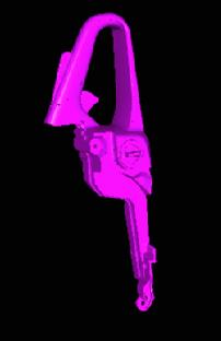
49 Creating a Turntable This task explains how to create a turntable which is the preliminary step before rendering an animation. Open the CHAINSAW.CATProduct document. 1. Click the Create Turntable icon to open the Turntable dialog box. The turntable symbol is displayed on the product: You can now define the model rotation axis. The entire product geometry will be able to rotate around that axis.


50 2. Position the shuttle to the desired location using the compass. 3. Define the turntable position along the u, v and w axes. 4. In the Turntable dialog box, indicate the rotation Start and End angles in degrees. The end angle is identified by an arrow. You can change the rotation direction by clicking the Reverse Direction button. 5. Click OK. The turntable is created.
51 Select the turntable in the specification tree then Turntable 1 object -> Definition... from the contextual menu to edit the turntable rotation axis.

52 Defining Animation Parameters This task shows you how to define animation parameters. This task implies that a turntable has been previously created. Open the CHAINSAW.CATProduct document Click the Create Shooting icon box. Click the Animation tab. to open the Shooting Definition dialog 3. Select the animation to be rendered from the pulldown list. 4. Key in the Frame count. 5. Click OK.

53 Previewing and Rendering a Turntable This task shows you how to animate a product in a simulation once you have defined the turntable and the animation parameters. Open the CHAINSAW.CATProduct document. 1. In the specification tree, select the simulation then Turntable 1 object -> Definition... to open the Simulation dialog box. 2. Click the Play Forward button to preview the animation. 3. You can modify, delete or skip the current shot by clicking the appropriate button. Select the interpolation which defines the number of steps between the shots you have recorded. Assigning a high number of interpolations amounts to replaying the scenario at a very low speed.
54 4. Use the other VCR buttons to play backward, step forward, modify the speed, etc. You can use one of the loop modes to: run the simulation once run the simulation in a continuous way run then reverse the simulation in a continuous way. When you launch the simulation, the animated object rotates around the turntable axis as shown below. Just position your pointer over the picture to see the animation:


55 5. Click the Render Shooting icon box opens. to render your animation. The Render dialog

56 6. Click the Render Animation icon. The animation is rendered and saved under a default location.

57 Do not forget to select the corresponding turntable in the Shooting Definition dialog box, otherwise the Render Animation icon will be grayed.
58 Environment Management Creating an Environment Managing Walls Defining the Wallpaper Previewing an Environment
.")
59 Creating an Environment This task will show you how to create an environment. Three environment types are available: box, sphere and cylinder. Open the REFLECT.CATProduct document Click the Create Box Environment icon if you want to create an environment with a rectangular shape (to represent a room for example). Zoom out then click anywhere in the geometry area to deselect the environment. You can also: Click the Create Sphere Environment icon if you want an environment having a spherical shape (to simulate a sky for example). Click the Create Cylinder Environment icon if you want an enviroment having a cylindrical shape.


60 When you create a new environment, it becomes the active one and the previous environment is deactivated in the specification tree. Only one active environment can be taken into account at rendering time. In our example, Environment 2 has been created and Environment 1 is deactivated. To activate an environment, just select it in the specification tree then select the Environment Active command from the contextual menu. 3. Position your pointer over the edges then use the green segments displayed to resize the environment walls: click and drag a segment to resize the walls according to the edges shift-click and drag a segment to resize the walls according to the center.


61 4. 5. Select the environment in the specification tree then right-click and choose the Edit -> Properties commands. The Properties panel is displayed. The Dimensions tab enables you to define the Length, Width and Height of the walls in millimeters. 6. Click the Position tab to interactively define: the environment translation from the Origin along the X, Y or Z axis. the environment translation along the X, Y, or Z Axis. The Feature Properties tab provides general information on the currently selected environment, e.g. its name, its creation date, etc.
62 You can also interactively position your environment by dragging the compass and dropping it onto the environment.
63 Managing Walls This task will introduce wall list management. Open the REFLECT.CATProduct document and create an environment as explained in Creating an Environment.. 1. In the specification tree, select an environment wall (or select it directly in the 3D window). 2. Right-click to display the contextual menu then uncheck the Wall Active option. The selected wall is grayed in the specification tree and is not taken into account at rendering time, as shown in the example below:
.")
64 Only the edges of the deactivated wall are displayed in the environment representation except if you have specified to display inactive environments (select the Tools->Options->Product commands then the Rendering tab). The geometry shadows are projected onto environment flat walls.
65
66 Defining the Wallpaper This task will show you how to associate images to your environment walls. Open the REFLECT.CATProduct document and create an environment as explained in Creating an Environment. 1. Select any wall of the environment on which the wallpaper should be defined. 2. Click the Apply Material icon to display the Library window.


67 The material must have a texture, otherwise an error panel will be displayed. Click the Fabrics tab, for example. Select Honeycomb. Click Apply Material to map the image texture of the material onto the selected wall. Repeat these steps for the other walls if you want to. Instead of clicking Apply, you can also use the contextual menu then copy the material before pasting it or drag and drop the material directly onto the wall. 7. Select the Apply Customized View icon in the View ->Render Style menu. The Custom View Mode dialog box is displayed Make sure that the Shading and Materials options are checked. Click OK. The material texture is mapped onto the selected wall.

68 In the above example, we have applied the following materials: Honeycomb, Wall of Bricks and Roughcast. You can modify the mapped texture properties by right-clicking the wallpaper in the specification tree and select the Properties or the Environment object->definition... command from the contextual menu. For more information, please refer to the Modified the Mapped Material section in the CATIA - Real Time Rendering User`s Guide.

69 Previewing an Environment This task will show you how to preview the environment reflections. Open the REFLECT.CATProduct document then create an environment with wallpapers as explained in Defining the Wallpaper. 1. Select the Tools->Options... command. 2. Choose the Infrastructure category. 3. Click the Rendering subcategory. The Display tab appears: 4. In the Reflections area, check the "Enable environment reflections" option. This option enables you to display an approximation of the environment reflection on reflecting objects (i.e. those having a non null reflectivity). 5. Indicate the texture size in pixels used when the product geometry is moved (e.g during a zoom, a translation, etc.) and when it is still using the "Texture size while moving" and "Texture size in static" options, respectively.

70 6. Specify the texture update threshold in degrees in the "Update when viewpoint rotated more than..." field. 7. Indicate the number of texture Computation passes. Here is an example of environment reflection on a product on which the Mirror material was applied:
71 Shooting Setting Image Quality Parameters

72 Setting Image Quality Parameters This task shows how to define the rendering style and quality parameters. Open the SHOOTING.CATProduct document and make sure that the Shading and Materials options are checked by selecting the View->Render Style->Customize View command. 1. Click the Create Shooting icon to open the Shooting Definition dialog box. Under the Frame tab, the Scene area lets you specify the elements to be rendered as well as the way of rendering them. By default, the active enviroment and any other active source are rendered.
.")
73 2. 3. In the Image size area, select the Camera, Environment and Active lights you want to render in the appropriate fields. A preview of the selected environment and the camera view is displayed. If no light is selected, a default directional light orthogonal to the image plane will be used (therefore producing very fews shadows). Define the size of the rendered image using the slider or manually. The number of pixels and the ratio are linked together. Whenever you change the pixel number, the ratio value is adjusted according to this number and reciprocally You can also use the Predefined format option to retrieve standard ratios. The corresponding Ratio is displayed. In the Output area, give a name to the image which is saved in a temporary folder by default. If you wish to save the picture On disk, you can change the default location. For more information, refer to the Saving Pictures task in this guide. The Quality tab lets you specify rendring, shadow and accuracy parameters, all of them impacting the rendering computation duration.
74 6. 7. Indicate the maximum reflections number. For instance, if you choose 2 and have two parallel mirrors in your scene, you will see the reflections of the reflections in each mirror ; choosing 1 instead, you won't see the secondary reflections Enter the geometry discretization factor: the geometry should be tessellated to be rendered, the smaller the figure, the finer the discretisation and therefore the final image quality. No texture rendering means that only the material lighting characteristics will be taken into account for the rendering and the environment wall texture are not rendered as well. This option can be used to speed up rendering at early stage for example. If you check the Show shadows option, only the shadows produced by the active lights will be rendered, otherwise no shadows are computed. This can be useful to speed up rendering. Now, let`s define the accuracy parameters that control the supersampling of the final image: 8. Select the accuracy type. Predefined: sets a fixed sag value for calculating tessellation on all objects. a low value means that a very fine mesh is used to render surfaces, but the drawback is that pre-processing and rendering will take more time. a high value means that a very coarse mesh is used, but the advantage is that pre-processing and rendering will take less time. Custom: the Custom parameters are defined through three values: a minimum number of samples, a maximum number of samples and a threshold. minimum sample: specifies the minimum number of samples, i.e. rays, taken at each corner of a pixel square. In our example, we have chosen a minimum of 1 ray at each corner of a square of 4 by 4 pixels. threshold: specifies the percentage over which an oversampling is done if the contrast in any RGB component between the currently calculated pixels and the neighboring pixels weighted by their sum is greater than this threshold. The lower this value, the more oversampling and the longer the rendering time. maximum sample: specifies the maximum number of samples, i.e. rays, per pixel. In our example, we have chosen a maximum of 1 ray per pixel. The preview area to the right shows you the effect of each setting. Note that anti-aliasing sets a better oversampling Click the Animation tab to define the animation parameters. For more information on the animation, refer to the Defining Animation Parameters task in this guide. Click OK. The next step is to render the shooting you have defined.
75 11. Click the Render Shooting icon to open the Render dialog box. A summary of the selected scene characteristics is displayed. 12. Select a shooting then click the Render Single Frame icon or the Render Animation icon, depending on the type of render you wish to create. The Rendering Output window opens and displays the rendering result. The following images illustrate different types of rendering:

76 Rendering showing textures, active lights, no shadow and a PVC material texture applied on the product.
 and no shadow.")
 and an Amber Mirror material")
77 Rendering showing no texture, no light (except the default light) and no shadow. Rendering showing textures, shadows, no light (except the default light) and an Amber Mirror material texture applied on the product.
78 Materials Using Materials for Rendering
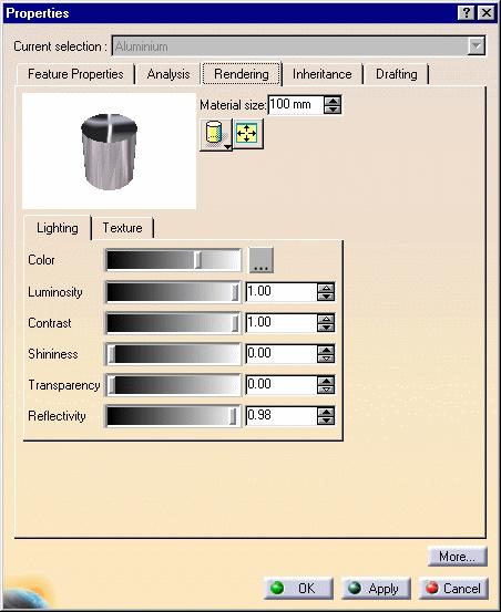
79 Using Materials for Rendering This task aims at showing you how to define the material attributes for a rendering. Open the TANK.CATProduct document. You can apply a material to each instance within a CATProduct. This functionality is especially relevant for rendering purposes since it lets you apply a different texture to each instance. Therefore, there will be as many materials as instances. The material preview will however display the last material applied to the instance Click the Apply material icon to open the Library window. Right-click the selected material in the specification tree then select the Properties command. The Properties dialog box is displayed.
80

81 3. Click the Rendering tab to define the Lighting parameters: luminosity, contrast, shininess and transparency. Luminosity: the intensity of light diffused in any direction by the object, even if not lit by any light source. Contrast: the intensity of light diffused by the object when lit by light sources. Typically, a shiny metal surface would have a diffuse reflectance value close to 0, while a piece of cardboard would have a value probably above 0.9. Shininess: the dullness of an object. Set the value to a minimum to generate very sharp highlights on very shiny surfaces. Set the shininess to a higher value to generate large specular spots creating a duller effect. Transparency: the degree of transparency of an object. The higher the value, the more transparent the object (in the example the value is 0.75), the lower the value, the more opaque the object. Note that Photo Studio does not handle refraction (i.e light deviation at transparent boundaries) but only transparency (i.e light is not bent by transparent boundaries). A preview is displayed in the Properties window but it slightly differs from the rendered image. Here are a few examples of rendered images with their corresponding lighting properties: Lighting Preview Quick Render
82
83 4. Click OK. The material attributes are defined.
84 Advanced Tasks Scene Management
85 Scene Management Creating a Scene
86 Creating a Scene This task explains how to quickly gives you a methodology to define the parameters involved in the scene creation, i.e. light, camera, textures. Open the HairDryer.CATProduct. Select also the Apply Customized View icon from the View->Render Style menu in order to check that the Shading and Materials options are on Create an empty environment (either box, cylindrical or spherical). Choose the point of view you want to use then click the Create Camera icon. 3. Click the Create Spot Light icon to define a conical light source then orientate the light as you wish with the help of the light preview on the environment walls.

87 4. Select the Light View command from the specification tree to make sure you have the desired illumination. This command lets you see the light point of view. Only the lit elements contained in the light preview shape will be lit at rendering time. Set the lighting attenuation in order that it does not end before the environment, otherwise the environment will be almost entirely shadowed Click the Quick Render icon to make a quick render from the light view. Perform as many modifications as necessary and check that what you get is really what you want to lit. Click the Camera item in the specification tree then select the Camera View command from the contextual menu. You can then perform changes and make quick renders to adjust the frameset to your needs.

88 7. Apply a texture on your environment and your part(s) by clicking the Apply Material icon and check the result by creating a quick render. Once you are satisfied, you can create a shooting to have a finer result. 8. Click the Create Shooting icon to define the shooting parameters. We advise you not to modify the default shooting parameters except those concerning accuracy. When the accuracy parameters is set beneath the mid value, you should obtain a result nearly as identical as the quick render. 9. Select a material in the specification tree then choose the Properties command from the contextual menu to adjust the material parameters.
")
89 10. Click the Render Shooting icon to check the result then go back to the material Properties to correct the parameter definition if necessary. Here are a few tips for lighting parameters: contrast: start by setting the Contrast to the minimum intensity: when you define the material lighting, the sum of all parameters (except Shininess) should be roughly equal to 1 to render the material with realism, but nothing forbids you to choose higher or lower sum values to achieve special effects: they may simply be harder to control. luminosity: use very carefully the Luminosity parameter ("good" values are around 10%) to avoid final color saturation reflectivity/shininess: set the Reflectivity and the Shininess at the same time transparency: if the material is transparent, define a Transparency value. We recommend you to define this parameter at the end.
90 When the result is satisfactory, adjust the shooting parameters to refine the result such as the reflection number, the anti-aliasing, etc. in the Shooting Definition dialog box. Click OK when you have finished. The scene is defined.

91 Workbench Description The Photo Studio Version 5 application window looks like this: Click the hotspots to see the related documentation. Menu Bar Scene Editor Toolbar Animation Toolbar Render Toolbar Sticker Toolbar

92 Menu Bar This section presents the menu bar tools and commands dedicated to the Photo Studio workbench. Many other operations are documented in the Version 5 Infrastructure User`s Guide. Start File Edit View Insert Tools Windows Help Start The Start menu is a navigation tool intended to help you toggle between different workshops. The contents of the Start menu vary according to the configurations and/or products installed. For... See... Infrastructure->Rendering Entering the Photo Studio workbench For more information about the Start menu, refer to the Infrastructure documentation. File The File menu lets you perform file creation, opening, saving and printing operations. Refer to the Infrastructure documentation. Edit The Edit menu lets you manipulate selected objects. Please refer to the Infrastructure documentation.

93 View The View menu lets you view document contents. Please refer to the Infrastructure documentation. View - >Toolbars For... See... Standard Workbench View Select Scene Editor Environment Management, Camera Management Apply Viewpoint Animation Stickers Render Animation Stickers Shooting, Animation Scene Editor Toolbar For... Create Box Environment Create Spot Light Create Camera See... Creating an Environment Defining the Light Parameters Creating a Camera from a Viewpoint Animation Toolbar For... See... Create Turntable Creating a Turntable Stickers Toolbar For... See... Apply Sticker Applying Stickers Render Toolbar For... See...

94 Create Shooting Render Shooting Quick Render Defining Animation Parameters, Setting Image Quality Parameters Animating in a Simulation, Setting Image Quality Parameters Creating a Quick Render Insert For... See... New Component New Product New CDM Component New Part Existing Component... Loading Products Tools The Tools menu lets you perform image capture and album management, set user preferences and manage macros. lease refer to the Infrastructure documentation. Window The Window menu lets you arrange document windows in relation one to the other. Please refer to the Infrastructure documentation. Help The Help menu lets you get help on the currently active command and the product in general. Please refer to the Infrastructure documentation.
95 Scene Editor Toolbar This toolbar contains the following tools for creating and managing scene elements: See Creating an Environment See Creating an Environment See Creating an Environment See Defining the Light Parameters See Defining the Light Parameters See Defining the Light Parameters See Creating a Camera from a Viewpoint
96 Animation Toolbar This toolbar contains the following tool for creating and managing animations: See Animations
97 Render Toolbar This toolbar contains the following tools for creating shootings and launching renderings. Note that this toolbar is only available in the CATIA Photo Studio product line. See Defining Animation Parameters, Setting Image Quality Parameters See Animating in a Simulation, Setting Image Quality Parameters See Creating a Quick Render
98 Sticker Toolbar This toolbar contains the following tool for applying stickers. Note that these functionnalities are only available in the ENOVIA Portal DMU line of products. See Applying Stickers
99 Customizing This section describes the different types of setting customization you can perform. All tasks described here deal with permanent setting customization. These tasks are: Rendering Display Rendering Output

100 Rendering This task explains how to customize Rendering display and output settings. Rendering Display 1. Select the Tools->Options... command then in the Infrastructure category, click the Rendering subcategory. The Display tab appears:
101 Setting Light Display This area lets you control the display of inactive lights: check the "No display for inactive lights" option to turn off inactive light display check the "Full display for inactive lights" option to turn on inactive light display. Setting Environment Display This area lets you to set the type of environment display: check the "No display for inactive environments" option to turn off inactive environment display check the "Simplified display for inactive environment environments" option to display inactive environments in a simplified way check the "Full display for inactive environments" option to turn on inactive environment display. Setting Reflection Display This area lets you define reflection parameters: check the "Enable environment reflections" to display environment reflections on reflecting objects check the "Show wall textures in reflections" to display wall textures on reflecting objects you can use the "Texture size in static" and the "Texture size while moving" options to indicate the texture size used when the product geometry is still and when it is moved the "Update when viewpoint..." field lets you specify the texture update threshold in degrees the "Computation passes" field lets you indicate the number of texture passes For more information on reflection display, refer to Previewing an Environment in the CATIA.Photo Studio User`s Guide.

102 Rendering Output 1. Select the Tools->Options... command then in the Infrastructure category, click the Rendering subcategory. 2. Click the Output tab: 3. In the Image Size area, specify whether the image size is defined "From active viewpoint" or "Fixed". If you selected the "Fixed" option, you must then enter the image width and height in pixels. 4. In the Output area, indicate the output type, i.e. On screen or On disk. If you selected the " On disk" option, you must then specify the new path and the new name of the image.
103
104 Glossary A accuracy animation anti-aliasing attenuation camera contrast directional light environment luminosity part point light product A parameter enabling to define the degree of precision of the rendering quality A rendering of successive positions of a product recorded in a simulation A graphic design technique that involves adding colored pixels to smooth the jagged edges of a graphic The action of lessening illumination C A rectangular-shaped element with a lens used to specify the chosen viewpoint to take the image The intensity of light diffused by the object when lit by light sources D A light coming from a given direction (like the sun, for instance) E A geometrical element, either rectangular, cylindrical or spherical, used to simulate interior as well as exterior scenes L The intensity of light emitted by any light source P A 3D entity obtained by combining different features A punctual illumination (like a bulb, for instance) A 3D entity containing several components
105 property raytracing reflection reflectivity rendering scene shininess shooting specification tree spot light sticker texture transparency turntable The attribute or characteristic of an object that defines its state, appearance or value R A photo-realistic image resulting from the calculation of the path of light reaching the product from various angles. Each pixel is created by calculating the behavior of a number of rays from these different points over the area covered by that pixel A light wave returned from a surface The ability to reflect light A photo-realistic drawing of three-dimensional objects S A reusable configuration enabling to put models on stage using cameras, light sources, environments, turntables The dullness of an object A set of parameters used to define a rendering An area of the document window reserved for viewing the design specifcations of a part, presented in the form of a tree structure A conical light An image that can be mapped onto a face of a product T An image that can be mapped onto a geometry The degree of transparency of an object. The object transparency defines its property of transmitting light so that elements lying beyond are seen A revolvable platform enabling to generate a sequence of images representing the model rotation around a user-defined axis
106 Index A C animation definition turntable creation preview Animation toolbar Apply Customized View command Apply Material command Apply Sticker command camera Camera Window command Create Box Environment command Create Camera command Create Cylindrical Environment command Create Directional Light command Create Sphere Environment command Create Point Light command Create Spot Light command commands Apply Customized View Apply Material Apply Sticker Camera Window Create Box Environment Create Camera Create Cylindrical Environment Create Directional Light Create Sphere Environment Create Point Light Create Spot Light Environment Active Properties,,, Update From View
107 E I L Wall Active environment creation wall list management wallpaper definition preview Environment Active command inserting existing components light M P managing wall list pictures pictures management save previewing an animation Properties command,,,
108 R S T U Render toolbar saving pictures scene creation Scene Editor toolbar shooting stickers applying modifying toolbars Animation Render Scene Editor turntable W Update From View command Wall Active command wallpaper wall list workbench,
Photo Studio Version 5 Release 13. Photo Studio
 Photo Studio Page 1 Preface Using This Guide More Information Conventions What's New? Getting Started Entering the Photo Studio Workbench Loading Products Creating a Quick Render Basic Tasks Camera Management
DMU Engineering Analysis Review
 Page 1 DMU Engineering Analysis Review Preface Using This Guide Where to Find More Information Conventions What's New? Getting Started Inserting a CATAnalysis Document Using DMU Space Analysis From CATAnalysis
DMU Engineering Analysis Review
 DMU Engineering Analysis Review Overview Conventions What's New? Getting Started Entering DMU Engineering Analysis Review Workbench Generating an Image Visualizing Extrema Generating a Basic Analysis Report
DMU Fitting Simulator
 Page 1 DMU Fitting Simulator Preface Using This Guide More Information Conventions What's New? Getting Started Using Tracks Starting a Session Recording a Track Using Automatic Path Finder Using the Smooth
Electrical Harness Flattening
 Electrical Harness Flattening Overview Conventions What's New? Getting Started Accessing the Electrical Harness Flattening Workbench Defining the Harness Flattening Parameters Extracting Data Flattening
Real Time Rendering Version 5 Release 13. Real Time Rendering
 Real Time Rendering Page 1 Preface Using This Guide Where to Find More Information Conventions What's New? Getting Started Applying Materials Modifying Mapped Material Basic Tasks Materials Applying a
Electrical Harness Installation
 Electrical Harness Installation Page 1 Overview Conventions What's New? Getting Started Entering the Workbench Setting Up the Options Creating a Bundle Segment Document Creating Construction Points Defining
DMU Space Analysis Version 5 Release 13. DMU Space Analysis
 Page 1 DMU Space Analysis Preface Using This Guide More Information Conventions What's New? Getting Started Setting Up Your Session Measuring Minimum Distances Sectioning Detecting Clashes Measuring Between
Fastening Review Overview Basic Tasks DMU Fastening Review Interoperability Workbench Description Customizing Index
 Fastening Review Overview Conventions Basic Tasks Displaying Joined Parts in a Balloon Running the Fastening Rules Analysis Reporting Creating Structural Reports Creating Flat Reports DMU Fastening Review
Equipment Support Structures
 Equipment Support Structures Overview Conventions What's New? Getting Started Setting Up Your Session Creating a Simple Structural Frame Creating Non-uniform Columns Creating Plates with Openings Bracing
Equipment Support Structures
 Page 1 Equipment Support Structures Preface Using This Guide Where to Find More Information Conventions What's New? Getting Started Setting Up Your Session Creating a Simple Structural Frame Creating Non-uniform
Electrical 3D Design & Documentation
 Electrical 3D Design & Documentation Page 1 Overview Conventions User Tasks Using Electrical 3D Design & Documentation Entering the Electrical Assembly Design Workbench Entering the Electrical Part Design
Tolerance Analysis of Deformable Assembly
 Tolerance Analysis of Deformable Assembly Overview Conventions What's New? Getting Started Entering the Workbench Creating a New Analysis Importing the Assembly Definition Computing a Tolerance Analysis
DMU Space Engineering Assistant User Guide
 DMU Space Engineering Assistant User Guide Overview Conventions What's New? Getting Started User Tasks Setting Up Your Session Running an Interference Analysis Workbench Description DMU Space Engineering
DMU Space Engineering Assistant User Guide
 Page 1 DMU Space Engineering Assistant User Guide Overview Conventions What's New? Getting Started User Tasks Setting Up Your Session Running a Interference Workbench Description DMU Space Engineering
DMU Optimizer Overview What's New? Getting Started User Tasks
 DMU Optimizer Overview Conventions What's New? Getting Started Starting a Session Generating a Silhouette Generating a Wrapping Generating a Thickness Generating an Offset Generating a Free Space User
Advanced Meshing Tools
 Page 1 Advanced Meshing Tools Preface Using This Guide More Information Conventions What's New? Getting Started Entering the Advanced Meshing Tools Workbench Defining the Surface Mesh Parameters Setting
Autodesk Fusion 360: Render. Overview
 Overview Rendering is the process of generating an image by combining geometry, camera, texture, lighting and shading (also called materials) information using a computer program. Before an image can be
Virtual MODELA USER'S MANUAL
 Virtual MODELA USER'S MANUAL Virtual MODELA is a program that simulates the movement of the tool on the screen. Contents Contents Part 1 Introduction 1-1 System Requirements... 4 1-2 Overview of Virtual
FreeStyle Shaper & Optimizer
 FreeStyle Shaper & Optimizer Preface What's New Getting Started Basic Tasks Advanced Tasks Workbench Description Customizing Glossary Index Dassault Systèmes 1994-99. All rights reserved. Preface CATIA
NC Manufacturing Verification
 NC Manufacturing Verification Overview Conventions What's New? User Tasks Accessing NC Manufacturing Verification Comparing the Machined Stock Part and the Design Part Pick Point Analysis in Video Mode
4) Finish the spline here. To complete the spline, double click the last point or select the spline tool again.
 Finish the spline here. To complete the spline, double click the last point or select the spline tool again.") 1) Select the line tool 3) Move the cursor along the X direction (be careful to stay on the X axis alignment so that the line is perpendicular) and click for the second point of the line. Type 0.5 for
1) Select the line tool 3) Move the cursor along the X direction (be careful to stay on the X axis alignment so that the line is perpendicular) and click for the second point of the line. Type 0.5 for
Getting Started with ShowcaseChapter1:
 Chapter 1 Getting Started with ShowcaseChapter1: In this chapter, you learn the purpose of Autodesk Showcase, about its interface, and how to import geometry and adjust imported geometry. Objectives After
COS 116 The Computational Universe Laboratory 10: Computer Graphics
 COS 116 The Computational Universe Laboratory 10: Computer Graphics As mentioned in lecture, computer graphics has four major parts: imaging, rendering, modeling, and animation. In this lab you will learn
Selective Space Structures Manual
 Selective Space Structures Manual February 2017 CONTENTS 1 Contents 1 Overview and Concept 4 1.1 General Concept........................... 4 1.2 Modules................................ 6 2 The 3S Generator
Electrical System Functional Definition
 Electrical System Functional Definition Preface What's New? Getting Started Basic Tasks Advanced Tasks Workbench Description Customizing Glossary Index Dassault Systèmes 1994-2000. All rights reserved.
NC Manufacturing Verification
 NC Manufacturing Verification Page 1 Preface Using This Guide Where to Find More Information Conventions What's New? User Tasks Accessing NC Manufacturing Verification Comparing the Machined Stock Part
To start, open or build a simple solid model. The bracket from a previous exercise will be used for demonstration purposes.
 Render, Lights, and Shadows The Render programs are techniques using surface shading, surface tones, and surface materials that are then presented in a scene with options for lights and shadows. Modifications
Electrical Wire Routing
 Electrical Wire Routing Page 1 Overview Conventions What's New? Getting Started Accessing the Workbench Creating the Bundle Selecting Systems with External Data Routing Wires from External Data User Tasks
Tutorial 4: Texture Mapping Techniques
 Tutorial 4: Texture Mapping Techniques Completion time 40 minutes In the previous tutorial we learned how to create materials, and how to assign texture maps to those materials. In this tutorial we will
Chapter 6 Formatting Graphic Objects
 Impress Guide Chapter 6 OpenOffice.org Copyright This document is Copyright 2007 by its contributors as listed in the section titled Authors. You can distribute it and/or modify it under the terms of either
Draw Guide. Chapter 7 Working with 3D Objects
 Draw Guide Chapter 7 Working with 3D Objects Copyright This document is Copyright 2011 2014 by the LibreOffice Documentation Team. Contributors are listed below. You may distribute or modify it under the
Circuit Board Design Version 5 Release 13. Circuit Board Design
 Circuit Board Design Page 1 Overview Conventions What's New? Getting Started Accessing the Circuit Board Workbench Creating a Board Pocket and Holes Constraint Area Exporting Data Importing Data User Tasks
COS 116 The Computational Universe Laboratory 10: Computer Graphics
 COS 116 The Computational Universe Laboratory 10: Computer Graphics As mentioned in lecture, computer graphics has four major parts: imaging, rendering, modeling, and animation. In this lab you will learn
DATACAD LLC. Software for A/E/C Professionals. Using o2c TECHNICAL BULLETIN. What is o2c? Installing the o2c Player. Functions of the o2c Player
 DATACAD LLC TECHNICAL BULLETIN Software for A/E/C Professionals Using o2c What is o2c? o2c displays three-dimensional, freely movable objects. Developed by mb Software, o2c depicts 3D objects as photo-realistic
Guide to WB Annotations
 Guide to WB Annotations 04 May 2016 Annotations are a powerful new feature added to Workbench v1.2.0 (Released May 2016) for placing text and symbols within wb_view tabs and windows. They enable generation
Numbers Basics Website:
 Website: http://etc.usf.edu/te/ Numbers is Apple's new spreadsheet application. It is installed as part of the iwork suite, which also includes the word processing program Pages and the presentation program
solidthinking Environment...1 Modeling Views...5 Console...13 Selecting Objects...15 Working Modes...19 World Browser...25 Construction Tree...
 Copyright 1993-2009 solidthinking, Inc. All rights reserved. solidthinking and renderthinking are trademarks of solidthinking, Inc. All other trademarks or service marks are the property of their respective
Working with the BCC Bump Map Generator
 Working with the BCC Bump Map Generator Bump mapping is used to create three dimensional detail on an image based on the luminance information in the image. The luminance value of each pixel of the image
Quick Start Tutorial
 Tutorial Tutorial: Build an Apple Welcome to Design 3D CX 7. This is a quick tutorial to get you started. In this tutorial you ll learn how to import an Adobe Illustrator file, Lathe it into a 3D object,
hdalbum User Designer Guide Collect Create Share Designer V 1.2
 hdalbum User Designer Guide 2017 Collect Create Share Designer V 1.2 Table of Contents Contents Welcome to the hdalbum Designer... 2 Features... 2 System Requirements... 3 Supported File Types... 3 Installing
Electrical System Functional Definition
 Electrical System Functional Definition Overview Conventions What's New? Getting Started Creating a New System Creating Equipment Creating Connectors Creating a Signal Connecting Saving Your System User
Piping Design. Site Map Preface Getting Started Basic Tasks Advanced Tasks Customizing Workbench Description Index
 Piping Design Site Map Preface Getting Started Basic Tasks Advanced Tasks Customizing Workbench Description Index Dassault Systèmes 1994-2001. All rights reserved. Site Map Piping Design member member
Version 14 COURSE UNIT 6. Visualisation
 Version 14 COURSE UNIT 6 Visualisation Table of Contents Introduction... 2 Preparation... 3 Materialization... 4 View position... 9 Camera... 10 Create design model view.... 12 Move background image...
Computer graphics Labs: Blender (2/3) LuxRender: Interior Scene Rendering
 LuxRender: Interior Scene Rendering") Computer graphics Labs: Blender (2/3) LuxRender: Interior Scene Rendering University of Liège Department of Aerospace and Mechanical engineering Designed with Blender 2.76b LuxRender During the first tutorial
Computer graphics Labs: Blender (2/3) LuxRender: Interior Scene Rendering University of Liège Department of Aerospace and Mechanical engineering Designed with Blender 2.76b LuxRender During the first tutorial
Prismatic Machining Overview What's New Getting Started User Tasks
 Prismatic Machining Overview Conventions What's New Getting Started Enter the Workbench Create a Pocketing Operation Replay the Toolpath Create a Profile Contouring Operation Create a Drilling Operation
Autodesk Fusion 360 Training: The Future of Making Things Attendee Guide
 Autodesk Fusion 360 Training: The Future of Making Things Attendee Guide Abstract After completing this workshop, you will have a basic understanding of editing 3D models using Autodesk Fusion 360 TM to
SolidWorks Implementation Guides. User Interface
 SolidWorks Implementation Guides User Interface Since most 2D CAD and SolidWorks are applications in the Microsoft Windows environment, tool buttons, toolbars, and the general appearance of the windows
Keynote 08 Basics Website:
 Website: http://etc.usf.edu/te/ Keynote is Apple's presentation application. Keynote is installed as part of the iwork suite, which also includes the word processing program Pages and the spreadsheet program
The Wireframe Update Buttons. The Frontface and Backface Buttons. The Project Designer 265
 The Wireframe Update Buttons The speed at which objects can be manipulated in the Project Designer viewport depends in part on the complexity of the object being moved. An object that is made up of many
Structure Preliminary Layout
 Page 1 Structure Preliminary Layout Preface Using This Guide Where to Find More Information What's New? Getting Started Setting Up Your Session Defining the Hull Form Setting Up Your Grid Creating Molded
12 APPLYING EFFECTS. Lesson overview
 12 APPLYING EFFECTS Lesson overview In this lesson, you ll learn how to do the following: Use various effects like Pathfinder, Distort & Transform, Offset Path, and Drop Shadow effects. Use Warp effects
Systems Space Reservation
 Systems Space Reservation Preface Using This Guide What's New? Getting Started Enter the Workbench Create an Equipment Reservation Set Correct Working Units and Grid Changing the Current Axis Saving Documents
Artlantis training for new users
 Artlantis training for new users page 2 This training program reviews the main features of Artlantis. You will learn about the various presentation types such as still images, ivisit 3D panoramas, VR objects
Animation Basics. Learning Objectives
 Animation Basics Learning Objectives After completing this chapter, you will be able to: Work with the time slider Understand animation playback controls Understand animation and time controls Morph compound
Working with the BCC Brick Generator
 Working with the BCC Brick Generator Brick is a versatile generator of tiled surfaces with realistic texture and lighting controls. The bricks can act as a Þlter on a layer or generate a brick surface
Human Posture Analysis
 Human Posture Analysis Overview Conventions What's New? Getting Started Creating a Manikin User Tasks Using the Posture Editor Selecting or Editing the DOF (Degree of Freedom) Displaying and Editing Angular
How to Create Greeting Cards using LibreOffice Draw
 by Len Nasman, Bristol Village Ohio Computer Club If you want to create your own greeting cards, but you do not want to spend a lot of money on special software, you are in luck. It turns out that with
Lesson 03: We will add water and will set the placing conditions for the material. WorldBuilder 3.5. for. About Digital Element Tutorials:
 Lesson 03: We will add water and will set the placing conditions for the material for WorldBuilder 3.5 About Digital Element Tutorials: This tutorial is available both in.pdf format and in Qarbon format,
Designer Reference 1
 Designer Reference 1 Table of Contents USE OF THE DESIGNER...4 KEYBOARD SHORTCUTS...5 Shortcuts...5 Keyboard Hints...5 MENUS...7 File Menu...7 Edit Menu...8 Favorites Menu...9 Document Menu...10 Item Menu...12
Advanced Rendering CHAPTER. Render Window. Learning Objectives. Image Pane
 CHAPTER Advanced Rendering Learning Objectives After completing this chapter, you will be able to: Make advanced rendering settings. Set the resolution for a rendering. Save a rendering to an image file.
FreeStyle Shaper Optimizer & Profiler
 FreeStyle Shaper Optimizer & Profiler Page 1 Preface Using This Guide More Information What's New? Getting Started Starting the FreeStyle Workbench Creating a First Surface Editing the Surface Creating
USING THE TRIBALL FOR POSITIONING
 USING THE TRIBALL FOR POSITIONING Although many important positioning tools are available, none are as versatile as the TriBall tool. This TriBall tool offers complete repositioning of many items: Shapes
Motic Images Plus 3.0 ML Software. Windows OS User Manual
 Motic Images Plus 3.0 ML Software Windows OS User Manual Motic Images Plus 3.0 ML Software Windows OS User Manual CONTENTS (Linked) Introduction 05 Menus and tools 05 File 06 New 06 Open 07 Save 07 Save
Beginning Paint 3D A Step by Step Tutorial. By Len Nasman
 A Step by Step Tutorial By Len Nasman Table of Contents Introduction... 3 The Paint 3D User Interface...4 Creating 2D Shapes...5 Drawing Lines with Paint 3D...6 Straight Lines...6 Multi-Point Curves...6
It s A Material World After All Alexander L.. Wood CAD Training Solutions, LLC
 November 30 December 3, 2004 Las Vegas, Nevada It s A Material World After All Alexander L.. Wood CAD Training Solutions, LLC GD21-3 Learn the basics of taking your 3D model into a rendered presentation.
USER MANUAL Table of Contents Slide 00 of 66
 USER MANUAL 1.5 www.dgflick.com Table of Contents Slide 00 of 66 Table of Contents Table of Contents... 1 1.0. Getting Started... 2 1.1. What is Video Xpress Suite?... 3 1.2. System Requirements to Run
Introduction to 3D Concepts
 PART I Introduction to 3D Concepts Chapter 1 Scene... 3 Chapter 2 Rendering: OpenGL (OGL) and Adobe Ray Tracer (ART)...19 1 CHAPTER 1 Scene s0010 1.1. The 3D Scene p0010 A typical 3D scene has several
Texture Mapping. Images from 3D Creative Magazine
 Texture Mapping Images from 3D Creative Magazine Contents Introduction Definitions Light And Colour Surface Attributes Surface Attributes: Colour Surface Attributes: Shininess Surface Attributes: Specularity
Reference Image. Source:
 Mesh Modeling By Immer Baldos This document is a tutorial on mesh modeling using Blender version 2.49b. The goal is to create a model of an elevator. This tutorial will tackle creating the elevator cart,
Human Posture Analysis
 Human Posture Analysis Page 1 Preface Using This Guide Where to Find More Information Conventions What's New? Getting Started Creating a Manikin User Tasks Using the Posture Editor Segments Degree of Freedom
Topics and things to know about them:
 Practice Final CMSC 427 Distributed Tuesday, December 11, 2007 Review Session, Monday, December 17, 5:00pm, 4424 AV Williams Final: 10:30 AM Wednesday, December 19, 2007 General Guidelines: The final will
Structure Preliminary Layout
 Structure Preliminary Layout Overview Conventions What's New? Getting Started Setting Up Your Session Defining the Hull Form Setting Up Your Grid Creating Molded Forms Creating a Compartment Creating Boundaries
Chapter 4- Blender Render Engines
 Chapter 4- Render Engines What is a Render Engine? As you make your 3D models in, your goal will probably be to generate (render) an image or a movie as a final result. The software that determines how
Photo Studio Optimizer
 CATIA V5 Training Foils Photo Studio Optimizer Version 5 Release 19 September 008 EDU_CAT_EN_PSO_FF_V5R19 Photo Studio Optimizer Objectives of the course Upon completion of this course you will be able
123D Catch - Tutorial
 123D Catch - Tutorial Autodesk s 123D Catch software (formerly Project Photofly) is based on photogrammetry. Photogrammetry is a process which derives geometric properties of an object from a series of
Compartment and Access
 Compartment and Access Page 1 Preface Using This Guide What's New? Getting Started Entering the Workbench Set Correct Working Units and Grid Saving Documents User Tasks Creating/Modifying Wall Systems
3D Modeling and Design Glossary - Beginner
 3D Modeling and Design Glossary - Beginner Align: to place or arrange (things) in a straight line. To use the Align tool, select at least two objects by Shift left-clicking on them or by dragging a box
Caustics - Mental Ray
 Caustics - Mental Ray (Working with real caustic generation) In this tutorial we are going to go over some advanced lighting techniques for creating realistic caustic effects. Caustics are the bent reflections
FLAMINGO CHEAT SHEET FOR ES 305 CLASS 5 Pages of Fresh Flamingo Goodness
 FLAMINGO CHEAT SHEET FOR ES 305 CLASS 5 Pages of Fresh Flamingo Goodness *Keep this PDF with you at all times it will help you to maneuver the vast and confusing ocean that is the Flamingo Materials Editor!
전산응용설계 (Computer Aided Design)
") 전산응용설계 (Computer Aided Design) CATIA (Computer Aided Three dimensional Interactive Application) 기계자동차공학부자동차공학전공 Chapter 3. CATIA 기초 학습내용 : 객체선택 (Selecting Objects) 객체감추기와보이기 (Hiding and Showing objects)
전산응용설계 (Computer Aided Design) CATIA (Computer Aided Three dimensional Interactive Application) 기계자동차공학부자동차공학전공 Chapter 3. CATIA 기초 학습내용 : 객체선택 (Selecting Objects) 객체감추기와보이기 (Hiding and Showing objects)
Word 3 Microsoft Word 2013
 Word 3 Microsoft Word 2013 Mercer County Library System Brian M. Hughes, County Executive Action Technique 1. Insert a Text Box 1. Click the Insert tab on the Ribbon. 2. Then click on Text Box in the Text
solidthinking User Interface
 Lesson 1 solidthinking User Interface This lesson introduces you to the solidthinking interface. The functions described represent the tools necessary for effectively managing the modeling of a project.
SketchUp Tool Basics
 SketchUp Tool Basics Open SketchUp Click the Start Button Click All Programs Open SketchUp Scroll Down to the SketchUp 2013 folder Click on the folder to open. Click on SketchUp. Set Up SketchUp (look
Keynote Basics Website:
 Keynote Basics Website: http://etc.usf.edu/te/ Keynote is Apple's presentation application. Keynote is installed as part of the iwork suite, which also includes the word processing program Pages. If you
Visualization Insider A Little Background Information
 Visualization Insider A Little Background Information Visualization Insider 2 Creating Backgrounds for 3D Scenes Backgrounds are a critical part of just about every type of 3D scene. Although they are
What is Publisher, anyway?
 What is Publisher, anyway? Microsoft Publisher designed for users who need to create and personalize publications such as marketing materials, business stationery, signage, newsletters and other items
This tutorial illustrates how to use TracePro for the analysis of LCD Back Lights. The steps include:
 Requirements Models: None Properties: None Editions: TracePro Expert Introduction This tutorial illustrates how to use TracePro for the analysis of LCD Back Lights. The steps include: Generating a solid
Building and Simulating a Task Lighting Model in LightTools
 Building and Simulating a Task Lighting Model in LightTools Synopsys 2012 1 Introduction to LightTools, Task Lighting Walkthrough Example This is an example of modeling a task lighting system in LightTools.
XnView 1.9. a ZOOMERS guide. Introduction...2 Browser Mode... 5 Image View Mode...15 Printing Image Editing...28 Configuration...
 XnView 1.9 a ZOOMERS guide Introduction...2 Browser Mode... 5 Image View Mode...15 Printing... 22 Image Editing...28 Configuration... 36 Written by Chorlton Workshop for hsbp Introduction This is a guide
Photogrammetry Guide to Creating Digital 3D Models
 Photogrammetry Guide to Creating Digital 3D Models By Emily Hauf (SUNY Geneseo) and the Paleontological Research Institution Guide Version 1.0 Part I - Photography Create studio setup with black cloth
Shape Sculptor Version 5 Release 13. Shape Sculptor
 Shape Sculptor Page 1 Overview Using This Guide Where to Find More Information What's New? Getting Started Entering the Workbench Importing a Polygonal Mesh Decimating a Polygonal Mesh User Tasks Input
LAB # 2 3D Modeling, Properties Commands & Attributes
 COMSATS Institute of Information Technology Electrical Engineering Department (Islamabad Campus) LAB # 2 3D Modeling, Properties Commands & Attributes Designed by Syed Muzahir Abbas 1 1. Overview of the
Turn your movie file into the homework folder on the server called Lights, Camera, Action.
 CS32 W11 Homework 3: Due MONDAY, APRIL 18 Now let s put the ball in a world of your making and have some fun. Create a simple AND WE MEAN SIMPLE environment for one of your ball bounces. You will assign
Autodesk Viz Render Illuminated Speaker; Charles Busa
 December 2-5, 2003 MGM Grand Hotel Las Vegas Autodesk Viz Render Illuminated Speaker; Charles Busa BD3-3 Autodesk Viz Render Illuminated This course is an introduction to the new Autodesk VIZ Render. Learn
12 APPLYING EFFECTS. Lesson overview
 12 APPLYING EFFECTS Lesson overview In this lesson, you ll learn how to do the following: Use various effects, such as Pathfinder, Scribble, and Drop Shadow. Use Warp effects to distort type. Create three-dimensional
Controlling the Drawing Display
 Controlling the Drawing Display In This Chapter 8 AutoCAD provides many ways to display views of your drawing. As you edit your drawing, you can control the drawing display and move quickly to different
Interior space in daylight Elsevier Inc. All rights reserved.
 Interior space in daylight Bonus Chapter 1 Day Lighting an Interior Space 1.1 Introduction In this chapter, you will learn about lighting an interior scene while you work on the lighting for the living
An Introduction to Maya. Maya. Used in industrial design, CAD, computer games and motion picture effects. The ambition is what get
 An Introduction to Maya Gustav Taxén gustavt@nada.kth.se 2D1640 Grafik och Interaktionsprogrammering VT 2006 Maya Used in industrial design, CAD, computer games and motion picture effects Special focus
BCC Sphere Transition
 BCC Sphere Transition The Sphere Transition shape models the source image onto a sphere. Unlike the Sphere filter, the Sphere Transition filter allows you to animate Perspective, which is useful in creating