Human Posture Analysis
|
|
|
- Brenda Flowers
- 5 years ago
- Views:
Transcription
1 Human Posture Analysis Page 1 Preface Using This Guide Where to Find More Information Conventions What's New? Getting Started Creating a Manikin User Tasks Using the Posture Editor Segments Degree of Freedom Value Display Predefined Postures Selecting or Editing the DOF (Degree of Freedom) Displaying and Editing Angular Limitations Angular Limitations Undo/Redo Direct Kinematics Selecting Manikin Display Attributes Library Management Load Angular Limitations Save Angular Limitations Locking and Unlocking DOFs Editing Preferred Angles
2 Preferred Angles: Reset, Mirror Copy, and Swap Functionality Using the Postural Score Adapting Range of Motion to Keep Best Posture Page 2 Workbench Description Human Posture Analysis Menu Bar Current Workbench Return to Previous Workbench Utilities Toolbar Angular Limitations Toolbar Preferred Angle Toolbar Glossary Index
3 Preface Page 3 Human Posture Analysis is based on a best-in-class human modeling system which, for many years, has permitted detailed investigation into humancentered design issues in the context of a workplace before it physically exists. Human Posture Analysis focuses on how human posture can affect task performance by analyzing local and global postures, preferred angles, and comfort. Human Posture Analysis permits users to quantitatively and qualitatively analyze all aspects of manikin posture. Whole body and localized postures can be examined, scored, iterated, and optimized to determine operator comfort and performance throughout the complete range of task motion in accordance with published comfort databases. User-friendly dialog boxes provide postural information for all segments of the manikin. Color-coding techniques ensure that problem areas can be quickly identified and iterated to optimize posture. Human Posture Analysis allows users to create specific comfort and strength libraries to meet the needs of individual applications.
4 How to Use this Guide Page 4 This book describes how to use the Human Posture Analysis product. Before you read it, you should be familiar with basic concepts such as document windows, standard tool bars, and view tool bars. If you are new user, start with the tutorial in the Getting Started section. The User Tasks section of the book provides procedures for using the features of the Human Posture Analysis product. A Workbench Description section describes each functional icon or command in the workbenches. The Glossary provides definitions of terms specific to Human Posture Analysis and related products.
5 Where to Find More Information Prior to reading this book, we recommend that you read the Human Builder User Guide. We also recommend: Human Measurements Editor Human Activities Analysis Conventions Page 5
6 Conventions Page 6 Certain conventions are used in CATIA, ENOVIA & DELMIA documentation to help you recognize and understand important concepts and specifications. Graphic Conventions The three categories of graphic conventions used are as follows: Graphic conventions structuring the tasks Graphic conventions indicating the configuration required Graphic conventions used in the table of contents Graphic Conventions Structuring the Tasks Graphic conventions structuring the tasks are denoted as follows: This icon... Identifies... estimated time to accomplish a task a target of a task the prerequisites the start of the scenario a tip a warning information basic concepts methodology reference information information regarding settings, customization, etc. the end of a task functionalities that are new or enhanced with this Release. allows you to switch back the full-window viewing mode. Graphic Conventions Indicating the Configuration Required
7 Graphic conventions indicating the configuration required are denoted as follows: Page 7 This icon... Indicates functions that are... specific to the P1 configuration specific to the P2 configuration specific to the P3 configuration Graphic Conventions Used in the Table of Contents Graphic conventions used in the table of contents are denoted as follows: This icon... Gives access to... Text Conventions Site Map Split View mode What's New? Overview Getting Started Basic Tasks User Tasks or the Advanced Tasks Workbench Description Customizing Reference Methodology Glossary Index The following text conventions are used: The titles of CATIA, ENOVIA and DELMIA documents appear in this manner throughout the text. File -> New identifies the commands to be used. Enhancements are identified by a blue-colored background on the text. How to Use the Mouse
8 Page 8 The use of the mouse differs according to the type of action you need to perform. Use this Whenever you read... mouse button... Select (menus, commands, geometry in graphics area,...) Click (icons, dialog box buttons, tabs, selection of a location in the document window,...) Double-click Shift-click Ctrl-click Check (check boxes) Drag Drag and drop (icons onto objects, objects onto objects) Drag Move Right-click (to select contextual menu)
9 What's New? Page 9 New Functionalities There is no new functionality in this release.
10 Getting Started Page 10 This tutorial provides an overview of Human Posture Analysis functionalities. It provides a step-by-step scenario showing you how to use key functions. The task described in this section is:
. 2. From the Start menu, select Ergonomics Design & Analysis -> Human Posture Analysis to create a new manikin. 3.")
11 Creating a Manikin Page 11 If you do not have an active product with a manikin, follow these steps to create a manikin. If you already have an active product containing a manikin, proceed to step Go to the Start menu (see below). 2. From the Start menu, select Ergonomics Design & Analysis -> Human Posture Analysis to create a new manikin. 3. Under the Manikin tab, select the father product, enter a name for the manikin, set the gender, and the percentile. Under the Optional tab, set the population, model-type, referential,

12 and choose whether or not to set the referential to a compass location. Page If you already have an active product containing a manikin, select the manikin or double-click a segment.
13 User Tasks Page 13 These are the tasks that a user performs using Human Posture Analysis:
14 Using the Posture Editor Page 14 This task describes the functions of the Posture Editor and how to use them to move manikin segments. The Posture Editor is a tool used to move manikin segments in forward kinematics. The segments or degrees of freedom (DOF) are moved one step at a time. This tool allows you to give a precise value to each degree of freedom of every joint. The manikin's structure consists of 68 articulated joints with 6 coupled joints (range of motion can depend on the position of a neighbor joint). 1. Select the Posture Editor icon. The Posture Editor dialog box is displayed on the screen when the manikin is selected.

15 Page 15 The Posture Editor dialog box is divided into five sections: The Degrees of Freedom can be modified either through the Value section or through their graphical representations.
16 Segments Page 16 This page describes the Segment section functionality of the Posture Editor dialog box. Displayed below the manikin name is a list of human body segments corresponding to the selection made in the Part menu. Click on the name of the segment in the list to select it. Part:
17 Page 17 The Part options menu allows you to choose the category of body segments to edit on the manikin The three categories listed are: 1. Hand: Edit the segments of the hand including the center of prehension. 2. Spine: Edit the segments making up the spinal column of the manikin. 3. Other: Edit all articulated segments excluding hand and spine segments. Other is the default option when the dialog box opens. Side: When you edit certain segments such as the arm, you can choose which side you want to work with: Left or Right. Left is the default option when the dialog box opens.
18 Degree of Freedom Page 18 This page describes the Degree of Freedom (DOF) functionality of the Posture Editor dialog box. 1. From the Degree of Freedom list, you can choose from three types of DOFs: flexion/extension abduction/adduction medial rotation/lateral rotation The default when the dialog box opens is flexion/extension.
19 Page 19 A segment can have up to three DOFs. Examples of possible segment DOFs are: The forearm has two DOFs: flexion/extension pronation/supination The arm has three DOFs flexion/extension abduction/adduction medial rotation/lateral rotation
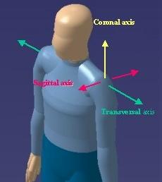
20 Page 20 Each of the DOF types, flexion/extension, abduction/adduction, and medial rotation/lateral rotation, also have specific movement types. These are: DOF Movement Type Axis flexion extension dorsiflexion hyperextension transversal abduction adduction medial rotation lateral rotation eversion, ulnar deviation, elevation inversion, radial deviation, depression supination pronation sagittal coronal
21 Page 21

22 Value Page 22 This page describes the Value functionality of the Posture Editor dialog box. Use the Value functionality to assign a precise posture to a segment. The value of the DOF is presented in angle and in percentage of the total range of motion (%). Value percentage slider

23 Page 23 The percentage (%) slider corresponds to the value in percentage of the total range of motion for the selected DOF. This value can be edited directly by sliding the cursor with the left mouse button. Value spinner This field allows you to enter a specific value in degrees using the keyboard. You can increment or decrement to segment rotation one unit at a time using the small arrows at the right end of this field. You can also change the step by using the spinner's contextual menu. Motion The motion field corresponds to the direction of movement, 0 degrees being the neutral point. Coupling: The range of motion (flexibility, functional limitation) for six pairs of segments on the manikin can be coupled, i.e., conditional to the position of another joint. These segments are: the claviculars, the arms, the forearms, the thighs, the legs, and the ankles. Coupling modifies the range of motion of these segments only. It has no effect on any relationship that may exist between other body segments.
24 By default, coupling is inactive. Page 24
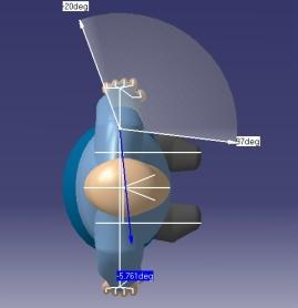
25 Display Page 25 This task describes the Display functionality of the Posture Editor dialog box. The Display function has two options: Angular Limitations and Animate Viewpoint. Angular Limitations (chart)

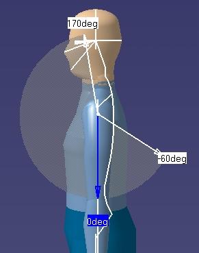
26 This check button displays or hides the graphical representation of the angular limitations for each degree of freedom. Two arrows limit this range of motion, which is set by default at the 50th percentile of the population. The green arrow shows the upper limit The yellow arrow shows the lower limit The blue arrow represents the segment's current position Page 26 Animate Viewpoint This option zooms on the selected segment and changes the viewpoint in order to provide the best possible view for that degree of freedom. This improves the range of motion chart display and as well as the capability to better manipulate the blue arrow.
27 Page 27

28 Predefined Postures Page 28 This task describes the Predefined Postures functionality of the Posture Editor dialog box.
29 Page 29 Use the Predefined Postures functionality to assign a predefined posture to the manikin. From the Predefined Postures list, choose from the six available postures. Stand Sit


30 Page 30 You can also select the manikin node in the specification tree. Rightclick the mouse to activate the contextual menu and choose Posture- >Sit.

31 Page 31 Reach
32 Page 32 Extended Reach


33 Page 33 Span

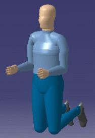
34 Page 34 Kneel
35 Page 35

36 Selecting or Editing the DOF (degrees of freedom) This procedure describes how to select or edit the manikin's DOF (degree of freedom). The DOF icon represents the movement being edited. For example, the DOF can be flexion/extension, abduction/adduction, rotation, etc. 1. Click on the Activate DOF icon to access the list of all available DOFs corresponding to the active segment (maximum of three). 2. Click one icon to select the corresponding DOF. 3. The system automatically modifies the viewpoint of the segment by a zoom corresponding to the DOF being selected. DOF1 Page 36 DOF2

37 Page 37 DOF3

38 Page 38 Displaying and Editing Angular Limitations This procedure describes how to display the values of the angular limitations for the DOF (degrees of freedom) that is currently active. It also describes how to set angular limitations as a percentage. 1. Select the Edit Angular Limitations icon and then select a segment. The limits arrows are displayed. These arrows are set by default at the mean values of movement limits. The colored region represents the total range of motion for that DOF. The green arrow shows the upper limit. The yellow arrow shows the lower limit. The blue arrow is used to change the position of the active segment. Selecting another segment while the command is running opens the angular limitations for the new segment and closes them for the previous one.

39 Page When you double-click the limits arrows, the Angular Limitations dialog box appears (see below). Using this dialog box, you can unlock the angular limits and modify the values directly with the sliders, the spinners, or by using the left mouse button to manipulate the spinner arrows. Select the Reset button to return to the default values. Select the Close button to exit the dialog box. 3. Select the Edit Angular Limitations icon to close the command and hide the angular limits arrows. Setting angular limitations as a percentage With this command, you can change the angular limitations of one or many degrees of freedom at once according to the percentage you choose. This percentage value represents the desired portion of population that must be able to reach the limit. At manikin creation, all angular limitations are set to limits that 50% of the population can reach. Using the Set Angular Limitations as a Percentage command, you may want to restrict (i.e., accommodate a narrower percentage of population) or widen (i.e., accommodate a larger percentage of population) these limits for a specific requirement of the population study. 1. Select a segment of the manikin. Hold down the Ctrl key on the keyboard to select more than one segment.
 and their current degree of freedom. 3.")
40 Page Select the Set Angular Limitations as a Percentage icon. The following dialog box is displayed: A read-only text field show the currently selected segments (or lines of sight) and their current degree of freedom. 3. Choose a percentile between 0 and 100 with the spinner. 4. Click on OK to confirm the modification of press Cancel to cancel the action. By clicking OK, both limits (min and max) of all degrees of freedom selected will take the specified percentage. The modification cannot be done if the selected degree of freedom is locked with a value that would be outside the new limits. In this case, the following dialog box is displayed:
41 Angular Limitations Undo/Redo Page 41 This procedure describes how to use the Undo/Redo feature with angular limitations. Undo/Redo allows you to reverse (cancel) the last angular limitation parameters applied to the manikin. Undo Click the Undo icon in the Standard toolbar to execute the Undo command. To load a library of angular limitations, see the library management task, Load Angular Limitations. The images below show the state of a manikin after applying the Undo command to a particular set of angular parameters. Initial angular limitations New angular limitations applied Undo command applied Redo This command repeats the last cancelled action. Click the Redo icon menu toolbar to execute the Redo command. in the main A Redo operation can also be undone. For example, you can restore the last angular

42 limitation parameters by invoking the Undo command. Page 42 Redo applied Undo applied In the current version of the Human Posture Analysis product, the angular limitations Undo/Redo applies to the following operations: Applying a set of angular limitations from a library.

43 Direct Kinematics Page 43 This procedure describes how to manipulate manikin segments. When you select the Edit Angular Limitations icon or the Edit Preferred Angles icon a blue arrow is displayed. You can change the position of the active segment by manipulating the blue arrow. The cursor changes to pickable when it is moved over the blue arrow. Press and hold down the left mouse button to manipulate the blue arrow and the segment.

44 Selecting Manikin Display Attributes This procedure describes how to access the various display attributes available for your manikin. 1. Select the Display Attributes icon. The Display Attributes dialog box is displayed. Page The manikin can be displayed using three different types of attributes: segments, ellipses, and surfaces. To change the manikin display, select the attribute type by activating the corresponding toggle button. 3. Various attribute display types can be selected at the same time. Segments

45 Page 45 Ellipses

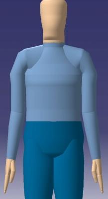
46 Page 46 Surfaces


47 Page The line of sight is designed to facilitate the manipulation of the manikin's field of vision. It can be selected as any other segment of the manikin.

48 Page The center of gravity cannot be selected and manipulated. If you manipulate any segment of the manikin, the center of gravity is dynamically updated. 6. By default, the manikin display is set to surfaces with a resolution of 32. The range of this parameter is from 4 to 128. Surface resolution: 4
49 Page 49 Surface resolution: 128
50 Page 50
51 Library Management Page 51 This procedure describes the commands that allow you to create, read, and update angular limitations and preferred angles libraries. A library is a collection of manikin-related data (i.e., postures, angular limitations, anthropometries, preferred angles, etc.) saved into a binary file. This file type usually bears the extension.swl. The two library management commands are:

52 Load Angular Limitations Page 52 This command allows you to load an existing library file. 1. Select the Load Library icon. The Open Human Library File dialog box is displayed. 2. Enter a file name and click Open. The Load Human Library dialog box is displayed showing the contents of the selected file.

53 Page Select an item and click Apply (or double-click the item). The progress indicator at the bottom of the window shows the load action. Depending on the type of item selected, select the Edit Angular Limitations icon or the Edit Preferred Angles icon to display the newly loaded values.
54 Page Select an item in the list and click on Remove to remove the item. 5. Select Close to exit from the dialog box.

55 Save Angular Limitations Command This command allows you to save the preferred angles of the angular limitations in a library file. 1. Select the Save in Library icon. The Save in Human Library dialog box is displayed. Page Select the Browse icon. The Select Library File dialog box is displayed.

56 Page Enter a file name or select one and click Open. If the file does not exist, a confirmation window is displayed to create it. 4. In the Save in Human Library dialog box, select the type to be saved from the Selection choices. 5. Click OK. The file is saved automatically and the progress indicator shows the save action. If the description is missing, an error window is displayed. 6. Select Cancel to exit the dialog box or to cancel the save action.
57 Page 57 Locking and Unlocking Degrees of Freedom (DOF) This tasks describes how to lock and unlock individual manikin degrees of freedom. Locking a degree of freedom means that the corresponding segment will not move by this DOF, either in forward kinematics or in inverse kinematics. The Lock/Unlock command will lock/unlock the current active DOF on the selected segments. The current active degree of freedom is indicated by the DOF icon. It is possible to lock/unlock the entire manikin for one particular degree of freedom if the Body node is selected in the specification tree when activating the lock/unlock command. For more information on locking and unlocking degrees of freedom, read the following sections: Locking DOFs Unlocking DOFs A manikin must be created or imported to complete the following procedures. Locking DOFs 1. To lock a degree of freedom, select the lock icon and then select the segment(s) to be locked. Multiple segments can be locked at the same time if they are pre-selected before the activation of the command. If the operation is successful, a message window will appear displaying the segments that have been locked.

58 Page Follow these steps to discover the existing locked segments on a specific manikin: a. Access the manikin Properties panel. To do this, right-click on the manikin from the product tree and select Properties. OR select Edit -> Properties from the main menu. The Properties panel appears.

59 Page 59 b. Select the Manikin tab which is the last tab of the panel. c. Select the Lock sub-tab which is dedicated to lock/unlock management. A selection list displays the names of the DOFs that are currently locked. Unlocking DOFs There are two ways to unlock DOFs: through the Properties panel with the Unlock icon
60 Page 60 Unlocking DOFs through the Properties panel 1. Access the manikin Properties panel. 2. Select the Lock sub-tab of the Manikin tab. 3. Select the DOF(s) that must be unlocked. 4. Click on the Unlock button. The selected DOFs are removed from the list. 5. Press the Apply button. The Apply button must be clicked to unlock the selected DOFs. Failure to do so will cause the operation to remain incomplete. Unlocking DOFs with the Unlock icon Select the Unlock icon, then select the segment(s) to be unlocked. Multiple segments can be unlocked at the same time if they are pre-selected before activation of the command. If the operation is successful, a message window will appear displaying the segments that have been unlocked.
61 Editing Preferred Angles Page 61 This procedure describes how to use the Edit Preferred Angles command. By dividing the total range of motion of the manikin into a certain number of ranges, it is possible to compute a global and a local score that quantifies the current posture. The Edit Preferred Angles command enables the user to define these ranges on individual DOFs. Selecting another segment while the command is running opens the Preferred angles dialog box for the new segment and closes it for the previous one. 1. Select the Edit Preferred Angles icon and then select a segment. The white arrows are displayed.

62 Page With the right mouse button, click anywhere in the white range of motion region to display the contextual data. Click on an option to activate it. Edit... Displays the Preferred Angles dialog box, makes the perimeter zone of the preferred angle being edited become red. You can modify the values of the arrows with the mouse or with the Preferred Angles dialog box. Add Displays the Preferred Angles dialog box and splits the selected
63 Page 63 range in half. You can modify the values of the arrows with the mouse or with the Preferred Angles dialog box. Remove Removes the selected preferred angle. 3. The Preferred Angles dialog box can be used to modify preferred angles.

64 Page 64 This dialog box contains the following elements: The name of the active body element The name of the active degree of freedom An editor to rename the preferred angle A spinner to change the score of the preferred angle Spinners to change the values of the limits A combo to select the preferred angle's color A slider to modify the transparency of the graphical region Sliders to modify the values of the limits An icon to add or modify a memo
65 Page 65 Navigation buttons to select a preferred angle in the list (next, previous, first, last) 4. Click Close to exit from the Preferred Angles dialog box. 5. Click the Edit Preferred Angles icon to cancel the command and hide the arrows.
66 Preferred Angles: Reset, Mirror Copy, and Swap Functionality This procedure describes how to copy and modify more than one set of preferred angles using these functions: Reset Mirror Copy Swap For more information on preferred angles, see Editing Preferred Angles. To access these functions, right-click on a segment, a segment node, a body, or a manikin. The following contextual menu appears: Page 66

67 Page 67 Reset The preferred angles of the segments selected will be erased and will return to their default state. The default state of the preferred angles in the following: only one preferred angle on the angular limitation range a score of zero a white color a transparency of 127

68 Page 68 Mirror Copy


69 Page 69 The mirror copy function will copy the preferred angles of the selected segment (in all degrees of freedom) onto the opposite side of the manikin. Mirror copy functionality can only be applied to segments that have an equivalent segment on the other side. If there is no equivalent segment, Mirror Copy will be disabled in the contextual menu. It is also disabled in the contextual menu when you select the entire manikin or the "Body" node. Swap The preferred angles of each selected segment will be copied to the opposite side of the manikin and vice versa. If a segment does not have an equivalent on the opposite side, Swap will be disabled in the contextual menu.

70 Using and Optimizing the Postural Score Page 70 This procedure describes how to use the List and Chart displays in the Postural Score Analysis dialog box and optimize the postural score. It also describes how to set segment coloring and how to customize the list and chart display in the Postural Score Analysis dialog box. The postural score feature is used to evaluate the manikin's posture. Once the preferred angles have been specified or loaded from a library, you can evaluate the posture using the postural score function. Click the Postural Score Analysis icon. The Postural Score Analysis dialog box is displayed with the List display as default. Filters This combo lists the specific DOFs that may be chosen as well as the choice of an average of all DOFs. Spine and Hand Choose the Whole Spine option to see all vertebras as one element. The score of that element will be the average score of all vertebras. This is the default. Choose the Each Vertebras option to see and score each vertebra individually. Choose the Whole Hand option to regroup each part of the fingers into a global element. This is the default. Choose the Each Fingers option to see and score each finger individually.
71 Page 71 Using the List display This is the default display and shows the percentage scores as a list. Both the List view and the Chart view contain the following elements: Global Score Represents the total score of the posture for all the segments combined. In this example, the manikin scores 11 points out of a possible 22, representing 50.00%. Current Score Gives the average score of all the items currently displayed in the list. Selected Score Represents the score of the posture for all selected items on the multi-list. In this example, the local score is 7 points out of a possible 9, representing 77.78%. Favorites Customizable, this displays preferred angles that are always displayed even if they have never been edited. By default a segment with a preferred angle is displayed even if it is not in the Favorites list. Customize this in the Tools->Options->Ergonomics Design->Human Posture Analysis- >Postural Score tab. The first Display field lists available segments. Choose one or select more than one using the Ctrl key. Move them into back and forth from the Available field to the Favorites field with the and buttons. Use the and buttons to move entire lists back and forth. Use the buttons to move favorite segments up or down in the sorting order.


72 Page 72 Using the Chart display Select the Chart radio button to view the percentage scores as charts. The Chart view also contains the same basic elements as the List display. The text for selected segments are turn blue. Customizing bar colors To customize chart bar colors, select Tools->Options->Ergonomics Design->Human Posture Analysis->Postural Score tab. Colors may be individualized for the whole hand, the whole spine, the global score, the current score, and the selected score.

73 Page 73 Segment Coloring Access to segment coloring is through the Properties dialog box. 1. Right-click the manikin in the specification tree and select Properties from the contextual menu. The Properties dialog box appears. 2. In the Manikin tab, select the Coloring sub-tab. Show Colors: These radio buttons are used to enable and disable the coloring. None deactivates the coloring. All activates the coloring. All but Maximum Scores activates the coloring on all segments except those with scores at their maximum. This feature can be used, for instance, to display colors only if the manikin goes out of its comfort zone. Degree of Freedom This combo is used to choose the degree of freedom to activate. This combo is enabled only if the coloring feature is active.
 The color shown for each segment is the color of the preferred angle defined for DOF2 of the corresponding segment, if it exists. Otherwise, no coloring is applied.")
74 Page 74 Flexion/Extension (DOF1) The color shown for each segment is the color of the preferred angle defined for DOF1 of the corresponding segment, if it exists. Otherwise, no coloring is applied. Abduction/Adduction(DOF2) The color shown for each segment is the color of the preferred angle defined for DOF2 of the corresponding segment, if it exists. Otherwise, no coloring is applied. Rotation (DOF3) The color shown for each segment is the color of the preferred angle defined for DOF3 of the corresponding segment, if it exists. Otherwise, no coloring is applied. Worst DOF The color shown for each segment is the color of the preferred angle defined for the lowest scoring DOF of the corresponding segment, if it exists. Otherwise, no coloring is applied. Element to color: These checkboxes are used to select the parts that will change color. They are enabled only if the coloring feature is active. Optimizing the postural score In the Preferred Angles toolbar, select the Find Best Posture command. This command changes the position of the body so as to maximize the global postural score of the manikin (i.e., yield a perfect score). If this command is invoked and there are no preferred angles or if the manikin is already in an optimal posture, the following message is displayed:
75 Adapting Range of Motion to Keep Best Posture The purpose of this task is to set the angular limitations of the selected segments so that these limitations correspond to the best range of motion, that is, the range of motion where the postural score is the highest. Please refer to Editing Preferred Angles for information on how to create preferred angles and assign scores to individual ranges of motion. Page To optimize the range of motion of any particular set of segments, first select the desired segment(s) and then click on the Optimize Posture icon. For each selected segment and for the current active degree of freedom, the command looks for all preferred angles created that have been assigned scores. The command then sets the angular limitations to the range containing the highest score. When this command is run, the posture of the segment(s) may change in order to reflect the new angular limitations. It is possible to use this command to optimize the posture of the manikin as a whole. To do this, select the Body node in the specification tree before activation the Optimize Posture command. This is particularly useful if the manikin's movements must be restricted to the "comfort zone". The postural score of such a manikin will stay at its highest, no matter how the manikin is moved. For more details, please refer to Using the Postural Score. It is possible that some or all of the selected segments may contain no preferred angle information or some of the angles may be locked. In these cases, and these cases only, the Optimize Posture command might fail. If the command fails for a subset of the selected segments, a message window will appear displaying the list of segments for which the optimization failed.

76 Page To reset the angular limitations of a manikin, select the segments that must be reset and click on the Reset to Default Angular Limitations icon.

77 Workbench Description Page 77 The Human Posture Analysis Version 5 application window looks like this. Click the hotspots to see the related documentation.
78 Human Posture Analysis Menu Bar Start File Edit View Insert Tools Window Help Page 78 Start For Human Posture Analysis See Creating a Manikin Tools For See Active DOF -> Selecting the DOF Display Angular Limitations Selecting Manikin Display Attributes Displaying and Editing Angular Limitations

79 Optimize/Reset -> Set Angular Limitations with Percentage Lock/Unlock -> Open Safework Library Save in Safework Library Preferred Angles Postural Score Page 79 Adapting Range of Motion to Keep Best Posture Displaying and Editing Angular Limitations Locking and Unlocking DOFs Library Management Library Management Editing Preferred Angles Using the Postural Score
80 Current Workbench Page 80 Shows the icon of the current workbench. When selected, a welcome dialog box is displayed.
81 Return to Previous Workbench Page 81 Exits the current workbench and returns you to the previous workbench.
82 Utilities Toolbar Page 82 See the Active DOF toolbar, below. See Selecting Manikin Display Attributes See Selecting the DOF See Selecting the DOF See Selecting the DOF
83 Angular Limitations Toolbar Page 83 See Displaying and Editing Angular Limitations See Adapting Range of Motion to Keep Best Posture See Adapting Range of Motion to Keep Best Posture See Displaying and Editing Angular Limitations See Locking and Unlocking DOFs See Locking and Unlocking DOFs See Library Management See Library Management
84 Preferred Angle Toolbar Page 84 See Editing Preferred Angles See Using the Postural Score See Using the Postural Score
85 Glossary Page 85 A abduction adduction angular limitations anthropometry The movement of a limb away from the median, or midline, of the body. The movement of a limb toward the median, or midline, of the body. The manikin's joint limitations. The study of proportional relationships between the shape, weight and size of body segments. C coronal axis The vertical axis perpendicular to the transverse plane that is dividing the body into superior and inferior portions. D degree(s) of freedom Each linear or rotary movement along or about a given axis. Manikin segments can have up to three DOFs. DOF dorsiflexion E degree(s) of freedom Ankle upward flexion movement elevation eversion extension Shoulder abduction movement Ankle abduction movement The act of straightening a limb at a joint.
86 Page 86 F flexion The act of bending a limb at a joint, thus forming an angle. H hyperextension Extending the extremity beyond anatomical position. I inversion Ankle adduction movement L lateral rotation line of sight The rotation of a body part away from the median, or midline, of the body. Designed to facilitate the manipulation of the manikin's field of vision. It can be selected as any other segment of the manikin. M manikin medial rotation A virtual human. The rotation of a body part toward the median, or midline, of the body. P postural score posture A function used to evaluate the manikin's posture. The position of the whole manikin (global posture) or of parts of the manikin such as hand posture (local posture).
87 Page 87 R radial deviation range of motion Wrist adduction movement (toward the radial bone, on the thumb side of the arm). The range of translation and rotation of a joint for each of its degrees of freedom. S sagittal axis segment supination Horizontal axis in the anterior-posterior orientation. This axis is perpendicular to the coronal plane that is dividing the body into anterior and posterior portions. A section of the manikin such as forearm, neck, thigh, ankle, etc. The movement of the forearm so that the hand rests palm up on a surface. T transversal axis Horizontal axis in the left-right orientation. This axis is perpendicular to the sagittal plane that is dividing the body into left and right portions. U ulnar deviation The entire area that can be seen when the eye is forward, including peripheral vision.
88 Index Page 88 A Angular Limitations toolbar angular limitations, displaying editing loading redo saving setting as a percentage undo C center of gravity, selecting commands Activate DOF 1 Activate DOF 2 Activate DOF 3 Display Attributes Edit Angular Limitations Edit Preferred Angles Load Library Mirror Copy Preferred Angles Optimize Posture Postural Score Analysis Posture Editor
89 Page 89 Reset Preferred Angles Reset to Default Angular Limitations Save in Library Set Angular Limitations as a Percentage Swap Preferred Angles creating a manikin Current Workbench toolbar D degrees of freedom editing locking unlocking degrees of freedom (DOF) selecting dialog box, Preferred Angles direct kinematics E editing preferred angles ellipses, selecting K kinematics, direct
90 L Page 90 library management line of sight, selecting M manikin, creating menu bar, Start P postural score optimizing postural score, analysis using Posture Editor dialog box degree of freedom display predefined postures segments value Posture Editor, using Preferred Angle toolbar preferred angles mirror copy reset swap Preferred Angles dialog box preferred angles, editing
91 Page 91 R range of motion, adapting to keep best posture resolution, manikin display Return to Previous Workbench toolbar S segments, selecting selecting, center of gravity ellipses line of sight manikin display attributes segments surfaces surfaces, selecting T toolbars, Angular Limitations Current Workbench Preferred Angle Return to Previous Workbench Utilities
92 Page 92 U Utilities toolbar W workbench description
Human Posture Analysis
 Human Posture Analysis Overview Conventions What's New? Getting Started Creating a Manikin User Tasks Using the Posture Editor Selecting or Editing the DOF (Degree of Freedom) Displaying and Editing Angular
Human Builder. Preface Using this Guide Where to Find More Information Conventions. What's New?
 Human Builder Page 1 Preface Using this Guide Where to Find More Information Conventions What's New? Getting Started Standard Manikin Creation Creating a Forearm/Hand Model Changing Manikin Display Attributes
DMU Engineering Analysis Review
 Page 1 DMU Engineering Analysis Review Preface Using This Guide Where to Find More Information Conventions What's New? Getting Started Inserting a CATAnalysis Document Using DMU Space Analysis From CATAnalysis
Equipment Support Structures
 Equipment Support Structures Overview Conventions What's New? Getting Started Setting Up Your Session Creating a Simple Structural Frame Creating Non-uniform Columns Creating Plates with Openings Bracing
Equipment Support Structures
 Page 1 Equipment Support Structures Preface Using This Guide Where to Find More Information Conventions What's New? Getting Started Setting Up Your Session Creating a Simple Structural Frame Creating Non-uniform
Electrical 3D Design & Documentation
 Electrical 3D Design & Documentation Page 1 Overview Conventions User Tasks Using Electrical 3D Design & Documentation Entering the Electrical Assembly Design Workbench Entering the Electrical Part Design
Electrical Harness Flattening
 Electrical Harness Flattening Overview Conventions What's New? Getting Started Accessing the Electrical Harness Flattening Workbench Defining the Harness Flattening Parameters Extracting Data Flattening
NC Manufacturing Verification
 NC Manufacturing Verification Overview Conventions What's New? User Tasks Accessing NC Manufacturing Verification Comparing the Machined Stock Part and the Design Part Pick Point Analysis in Video Mode
Tolerance Analysis of Deformable Assembly
 Tolerance Analysis of Deformable Assembly Overview Conventions What's New? Getting Started Entering the Workbench Creating a New Analysis Importing the Assembly Definition Computing a Tolerance Analysis
DMU Engineering Analysis Review
 DMU Engineering Analysis Review Overview Conventions What's New? Getting Started Entering DMU Engineering Analysis Review Workbench Generating an Image Visualizing Extrema Generating a Basic Analysis Report
NC Manufacturing Verification
 NC Manufacturing Verification Page 1 Preface Using This Guide Where to Find More Information Conventions What's New? User Tasks Accessing NC Manufacturing Verification Comparing the Machined Stock Part
Electrical Harness Installation
 Electrical Harness Installation Page 1 Overview Conventions What's New? Getting Started Entering the Workbench Setting Up the Options Creating a Bundle Segment Document Creating Construction Points Defining
Advanced Meshing Tools
 Page 1 Advanced Meshing Tools Preface Using This Guide More Information Conventions What's New? Getting Started Entering the Advanced Meshing Tools Workbench Defining the Surface Mesh Parameters Setting
Fastening Review Overview Basic Tasks DMU Fastening Review Interoperability Workbench Description Customizing Index
 Fastening Review Overview Conventions Basic Tasks Displaying Joined Parts in a Balloon Running the Fastening Rules Analysis Reporting Creating Structural Reports Creating Flat Reports DMU Fastening Review
DMU Space Engineering Assistant User Guide
 DMU Space Engineering Assistant User Guide Overview Conventions What's New? Getting Started User Tasks Setting Up Your Session Running an Interference Analysis Workbench Description DMU Space Engineering
DMU Space Engineering Assistant User Guide
 Page 1 DMU Space Engineering Assistant User Guide Overview Conventions What's New? Getting Started User Tasks Setting Up Your Session Running a Interference Workbench Description DMU Space Engineering
Electrical System Functional Definition
 Electrical System Functional Definition Preface What's New? Getting Started Basic Tasks Advanced Tasks Workbench Description Customizing Glossary Index Dassault Systèmes 1994-2000. All rights reserved.
DMU Fitting Simulator
 Page 1 DMU Fitting Simulator Preface Using This Guide More Information Conventions What's New? Getting Started Using Tracks Starting a Session Recording a Track Using Automatic Path Finder Using the Smooth
Electrical System Functional Definition
 Electrical System Functional Definition Overview Conventions What's New? Getting Started Creating a New System Creating Equipment Creating Connectors Creating a Signal Connecting Saving Your System User
Human Motion. Session Speaker Dr. M. D. Deshpande. AML2506 Biomechanics and Flow Simulation PEMP-AML2506
 AML2506 Biomechanics and Flow Simulation Day 02A Kinematic Concepts for Analyzing Human Motion Session Speaker Dr. M. D. Deshpande 1 Session Objectives At the end of this session the delegate would have
USING THE TRIBALL FOR POSITIONING
 USING THE TRIBALL FOR POSITIONING Although many important positioning tools are available, none are as versatile as the TriBall tool. This TriBall tool offers complete repositioning of many items: Shapes
Electrical Wire Routing
 Electrical Wire Routing Page 1 Overview Conventions What's New? Getting Started Accessing the Workbench Creating the Bundle Selecting Systems with External Data Routing Wires from External Data User Tasks
DMU Space Analysis Version 5 Release 13. DMU Space Analysis
 Page 1 DMU Space Analysis Preface Using This Guide More Information Conventions What's New? Getting Started Setting Up Your Session Measuring Minimum Distances Sectioning Detecting Clashes Measuring Between
Comparison of Postures from Pen and Mouse Use
 Global Ergonomic Technologies P.O. Box 2667 Guerneville, CA 95446 - U.S.A. Phone: (77) 869-194 Fax: (77) 869-1956 Comparison of Postures from Pen and Mouse Use June 8, 1998 Introduction There are a variety
CellaVision Proficiency Software
 CellaVision Proficiency USER S MANUAL 2.3 CellaVision Proficiency Preface CellaVision is a trademark of CellaVision AB. All other trademarks used in this document are property of their respective owners.
Adjust model for 3D Printing. Positioning - Orientate the part 13,0600,1489,1604(SP6)
") Adjust model for 3D Printing 13,0600,1489,1604(SP6) In this document, we will learn about. Position and Orientate a Body means that we move and rotate the body to fit our 3D printing considerations. Typical
Adjust model for 3D Printing 13,0600,1489,1604(SP6) In this document, we will learn about. Position and Orientate a Body means that we move and rotate the body to fit our 3D printing considerations. Typical
Circuit Board Design Version 5 Release 13. Circuit Board Design
 Circuit Board Design Page 1 Overview Conventions What's New? Getting Started Accessing the Circuit Board Workbench Creating a Board Pocket and Holes Constraint Area Exporting Data Importing Data User Tasks
Prismatic Machining Overview What's New Getting Started User Tasks
 Prismatic Machining Overview Conventions What's New Getting Started Enter the Workbench Create a Pocketing Operation Replay the Toolpath Create a Profile Contouring Operation Create a Drilling Operation
Adobe Flash CS4 Part 4: Interactivity
 CALIFORNIA STATE UNIVERSITY, LOS ANGELES INFORMATION TECHNOLOGY SERVICES Adobe Flash CS4 Part 4: Interactivity Fall 2010, Version 1.0 Table of Contents Introduction... 2 Downloading the Data Files... 2
Electrical Library Version 5 Release 13. Electrical Library
 Electrical Library Page 1 Overview Conventions What's New? Getting Started Entering the Electrical Part Design Workbench Defining a Single Insert Connector Defining a Cavity Connection Point Entering Electrical
Press the Plus + key to zoom in. Press the Minus - key to zoom out. Scroll the mouse wheel away from you to zoom in; towards you to zoom out.
 Navigate Around the Map Interactive maps provide many choices for displaying information, searching for more details, and moving around the map. Most navigation uses the mouse, but at times you may also
CHAPTER 1 COPYRIGHTED MATERIAL. Getting to Know AutoCAD. Opening a new drawing. Getting familiar with the AutoCAD and AutoCAD LT Graphics windows
 CHAPTER 1 Getting to Know AutoCAD Opening a new drawing Getting familiar with the AutoCAD and AutoCAD LT Graphics windows Modifying the display Displaying and arranging toolbars COPYRIGHTED MATERIAL 2
Guide to WB Annotations
 Guide to WB Annotations 04 May 2016 Annotations are a powerful new feature added to Workbench v1.2.0 (Released May 2016) for placing text and symbols within wb_view tabs and windows. They enable generation
Electrical Cableway Routing
 Electrical Cableway Routing Preface Using This Guide What's New? Getting Started Entering the Workbench Placing a Hanger Routing a Loft Through Hangers Placing a Conduit on a Run Saving Documents Updating
Mannequin Simulation. D. Chablat. 21/11/2016 D. Chablat 1
 Mannequin Simulation D. Chablat 21/11/2016 D. Chablat 1 DELMIA workbench Use of Delmia's 5 virtual human workbench Human Builder Human Activity Analysis Human Posture Analysis Human Measurements Editor
1 General Principles. General Principles. In this chapter 1-1
 1 General Principles In this chapter 1 General Principles 1.1 User Interface 1.2 Title bar 1.3 Menu bar 1.4 Standard Toolbar 1.5 The drawing area 1.6 Component tabs 1.7 Status Bar 1.8 Manipulating Components
Animations in Creo 3.0
 Animations in Creo 3.0 ME170 Part I. Introduction & Outline Animations provide useful demonstrations and analyses of a mechanism's motion. This document will present two ways to create a motion animation
In this tutorial, you will create a scene with sandman dispersing in sand, as shown in in the image below.
 Particle Flow In this tutorial, you will create a scene with sandman dispersing in sand, as shown in in the image below. Creating the Project Folder 1. Create a project folder with the name c17_tut1 at
Human Measurements Editor
 Human Measurements Editor Overview Conventions What's New? Getting Started Access from the Start Menu Access Using the Specification Tree Access from the Manikin Tools Toolbar User Tasks Editing Anthropometric
SMART Meeting Pro 4.2 personal license USER S GUIDE
 smarttech.com/docfeedback/170973 SMART Meeting Pro 4.2 personal license USER S GUIDE Product registration If you register your SMART product, we ll notify you of new features and software upgrades. Register
Piping Design. Site Map Preface Getting Started Basic Tasks Advanced Tasks Customizing Workbench Description Index
 Piping Design Site Map Preface Getting Started Basic Tasks Advanced Tasks Customizing Workbench Description Index Dassault Systèmes 1994-2001. All rights reserved. Site Map Piping Design member member
Structure Preliminary Layout
 Page 1 Structure Preliminary Layout Preface Using This Guide Where to Find More Information What's New? Getting Started Setting Up Your Session Defining the Hull Form Setting Up Your Grid Creating Molded
StickFont Editor v1.01 User Manual. Copyright 2012 NCPlot Software LLC
 StickFont Editor v1.01 User Manual Copyright 2012 NCPlot Software LLC StickFont Editor Manual Table of Contents Welcome... 1 Registering StickFont Editor... 3 Getting Started... 5 Getting Started...
for ArcSketch Version 1.1 ArcSketch is a sample extension to ArcGIS. It works with ArcGIS 9.1
 ArcSketch User Guide for ArcSketch Version 1.1 ArcSketch is a sample extension to ArcGIS. It works with ArcGIS 9.1 ArcSketch allows the user to quickly create, or sketch, features in ArcMap using easy-to-use
PC-Kits USER GUIDE. SOFTWARE SUPPORT Monday - Friday 8:00am - 4:00pm Pacific Time
 PC-Kits USER GUIDE SOFTWARE SUPPORT Monday - Friday 8:00am - 4:00pm Pacific Time 1-800-356-0709 Copyright Visual Health Information. All rights reserved. CONTENTS STARTING VHI PC-KITS... 1 ACTIVATING VHI
Primal s 3D Real-time on Anatomy.tv
 USER GUIDE Primal s 3D Real-time on Anatomy.tv Welcome to our user guide to 3D Real-time on Anatomy.tv. Please read on, or select one of the links opposite to jump straight to a particular topic. Anatomy.tv
SMART Meeting Pro PE 4.1 software
 Help us make this document better smarttech.com/feedback/170973 SMART Meeting Pro PE 4.1 software USER S GUIDE Product registration If you register your SMART product, we ll notify you of new features
Learning Autodesk Maya The Modeling & Animation Handbook. Free Models From Turbo Squid Value US $ Official Autodesk Training Guide
 Free Models From Turbo Squid Value US $239.00 Official Autodesk Training Guide Learning Autodesk Maya 2008 The Modeling & Animation Handbook A hands-on introduction to key tools and techniques in Autodesk
Introduction to Microsoft Office PowerPoint 2010
 Introduction to Microsoft Office PowerPoint 2010 TABLE OF CONTENTS Open PowerPoint 2010... 1 About the Editing Screen... 1 Create a Title Slide... 6 Save Your Presentation... 6 Create a New Slide... 7
Work with RSS Feeds. Procedures. Add an RSS Text Object CHAPTER. Procedures, page 7-1
 CHAPTER 7 Revised: November 15, 2011 s, page 7-1 s Add an RSS Text Object, page 7-1 Rename an RSS Text Object, page 7-2 Delete or Restore an RSS Text Object, page 7-4 Manipulate an RSS Text Object, page
Working with the Dope Sheet Editor to speed up animation and reverse time.
 Bouncing a Ball Page 1 of 2 Tutorial Bouncing a Ball A bouncing ball is a common first project for new animators. This classic example is an excellent tool for explaining basic animation processes in 3ds
GCC vinyl cutter, cutting plotter for sign making
 Plotter Setup In "Plotter Setup," you can choose "Plotter List," "Environment," "Pen," and so on. [Plotter list] In this area, you can choose the machine type and set some basic information for your plotter
COPYRIGHTED MATERIAL. Making Excel More Efficient
 Making Excel More Efficient If you find yourself spending a major part of your day working with Excel, you can make those chores go faster and so make your overall work life more productive by making Excel
Schematics in ArcMap Tutorial
 Schematics in ArcMap Tutorial Copyright 1995-2010 Esri All rights reserved. Table of Contents Introducing Schematics in ArcMap Tutorial........................ 3 Exercise 1: Getting familiar with Schematics
The Auslan System Sign Editor User Manual
 The Auslan System Sign Editor User Manual Preface: This manual explains how to construct, edit, or design their own sign language signs. The software referred to in this manual, the Auslan Sign Editor,
The objective of this tutorial is to present Model Based Calculations. These are calculations that only make sense relative to rigid segments.
 C-Motion Online Documentation Visual3D : Model Based Computations Objectives (# 1388) The objective of this tutorial is to present Model Based Calculations. These are calculations that only make sense
Introduction And Overview ANSYS, Inc. All rights reserved. 1 ANSYS, Inc. Proprietary
 Introduction And Overview 2006 ANSYS, Inc. All rights reserved. 1 ANSYS, Inc. Proprietary The ANSYS Workbench represents more than a general purpose engineering tool. It provides a highly integrated engineering
BND TechSource. Ergonomic Manikin Manipulation using CATIA V5 DMU Kinematics. (Steps 5-11 the optimized solution)
") Ergonomic Manikin Manipulation using CATIA V5 DMU Kinematics (Steps 5-11 the optimized solution) In the previous example, we showed a simple solution to manipulate an Ergonomic Manikin using CATIA DMU
Ergonomic Manikin Manipulation using CATIA V5 DMU Kinematics (Steps 5-11 the optimized solution) In the previous example, we showed a simple solution to manipulate an Ergonomic Manikin using CATIA DMU
TUTORIAL 03: RHINO DRAWING & ORGANIZATIONAL AIDS. By Jeremy L Roh, Professor of Digital Methods I UNC Charlotte s School of Architecture
 TUTORIAL 03: RHINO DRAWING & ORGANIZATIONAL AIDS By Jeremy L Roh, Professor of Digital Methods I UNC Charlotte s School of Architecture Modeling in 3D requires the use of various drawing and organizational
Aerospace Sheetmetal Design
 Aerospace Sheetmetal Design Page 1 Overview Conventions What's New? Getting Started Entering the Aerospace SheetMetal Design Workbench Defining the Aerospace SheetMetal Parameters Creating a Web from a
DMU Optimizer Overview What's New? Getting Started User Tasks
 DMU Optimizer Overview Conventions What's New? Getting Started Starting a Session Generating a Silhouette Generating a Wrapping Generating a Thickness Generating an Offset Generating a Free Space User
Tutorial 1: Welded Frame - Problem Description
 Tutorial 1: Welded Frame - Problem Description Introduction In this first tutorial, we will analyse a simple frame: firstly as a welded frame, and secondly as a pin jointed truss. In each case, we will
Gamepad Controls. Figure 1: A diagram of an Xbox controller. Figure 2: A screenshot of the BodyViz Controller Panel. BodyViz 3 User Manual 1
 BodyViz User Manual Gamepad Controls The first step in becoming an expert BodyViz user is to get acquainted with the Xbox gamepad, also known as a controller, and the BodyViz Controller Panel. These can
Exercise 2: Bike Frame Analysis
 Exercise 2: Bike Frame Analysis This exercise will analyze a new, innovative mountain bike frame design under structural loads. The objective is to determine the maximum stresses in the frame due to the
Word 2013 Quick Start Guide
 Getting Started File Tab: Click to access actions like Print, Save As, and Word Options. Ribbon: Logically organize actions onto Tabs, Groups, and Buttons to facilitate finding commands. Active Document
GDL Toolbox 2 Reference Manual
 Reference Manual Archi-data Ltd. Copyright 2002. New Features Reference Manual New Save GDL command Selected GDL Toolbox elements can be exported into simple GDL scripts. During the export process, the
SILVACO. An Intuitive Front-End to Effective and Efficient Schematic Capture Design INSIDE. Introduction. Concepts of Scholar Schematic Capture
 TCAD Driven CAD A Journal for CAD/CAE Engineers Introduction In our previous publication ("Scholar: An Enhanced Multi-Platform Schematic Capture", Simulation Standard, Vol.10, Number 9, September 1999)
About this document. Introduction. Where does Life Forms fit? Prev Menu Next Back p. 2
 Prev Menu Next Back p. 2 About this document This document explains how to use Life Forms Studio with LightWave 5.5-6.5. It also contains short examples of how to use LightWave and Life Forms together.
Product Structure Version 5 Release 13. Product Structure
 Product Structure Page 1 Site Map Preface Conventions What's New? Basic Tasks Entering the Product Structure Workbench Opening a CATProduct with a Progress Bar Selecting Products only Selecting Modes Inserting
PowerPoint 2016 Building a Presentation
 PowerPoint 2016 Building a Presentation What is PowerPoint? PowerPoint is presentation software that helps users quickly and efficiently create dynamic, professional-looking presentations through the use
THE EASTMAN Easicut v2.1
 THE EASTMAN Easicut v2.1 User's Manual This manual must be used in conjunction with the M9000 Machine Instruction and Service manual, Form #E-509-Instructions. 779 Washington St., Buffalo, N.Y. 14203-1396
2 SELECTING AND ALIGNING
 2 SELECTING AND ALIGNING Lesson overview In this lesson, you ll learn how to do the following: Differentiate between the various selection tools and employ different selection techniques. Recognize Smart
Structure Preliminary Layout
 Structure Preliminary Layout Overview Conventions What's New? Getting Started Setting Up Your Session Defining the Hull Form Setting Up Your Grid Creating Molded Forms Creating a Compartment Creating Boundaries
Systems Space Reservation
 Systems Space Reservation Preface Using This Guide What's New? Getting Started Enter the Workbench Create an Equipment Reservation Set Correct Working Units and Grid Changing the Current Axis Saving Documents
FreeStyle Shaper & Optimizer
 FreeStyle Shaper & Optimizer Preface What's New Getting Started Basic Tasks Advanced Tasks Workbench Description Customizing Glossary Index Dassault Systèmes 1994-99. All rights reserved. Preface CATIA
User Manual Version 1.1 January 2015
 User Manual Version 1.1 January 2015 - 2 / 112 - V1.1 Variegator... 7 Variegator Features... 7 1. Variable elements... 7 2. Static elements... 7 3. Element Manipulation... 7 4. Document Formats... 7 5.
BASICS OF MOTIONSTUDIO
 EXPERIMENT NO: 1 BASICS OF MOTIONSTUDIO User Interface MotionStudio combines draw, paint and animation in one easy easy-to-use program gram to save time and make work easy. Main Window Main Window is the
XPEL DAP SUPPORT. DAP Tool List & Overview DESCRIPTION ICON/TOOL (SHORTCUT)
") Pointer (S) Left-click on individual entities to add them to the current selection (selected entities will turn red). If the entity selected is a member of a group, the entire group will be added to the
Pointer (S) Left-click on individual entities to add them to the current selection (selected entities will turn red). If the entity selected is a member of a group, the entire group will be added to the
Undo Button Clicking this tool will undo the last action. Clicking on this tool multiple times will undo all subsequent changes that were made.
 SMS Featured Icons: Editor Window This document includes a brief description of the tools in the SMS Desktop Software Editor windows, as well as showing you the toolbar shortcuts to easily access these
Tutorial 3D Max (for beginners) PART I
 PART I") Tutorial 3D Max (for beginners) PART I The Interface Introduction This tutorial gives a brief explanation of the MAX interface items commonly used and introduces you to the important areas of the interface.
Tutorial 3D Max (for beginners) PART I The Interface Introduction This tutorial gives a brief explanation of the MAX interface items commonly used and introduces you to the important areas of the interface.
Autodesk Navisworks Freedom Quick Reference Guide
 WP CAD 00074 March 2012 Guide by Andy Davis Autodesk Navisworks Freedom Quick Reference Guide Quick Reference Guide to Autodesk Navisworks Freedom Opening a Model To open a model, click on the Application
Publication Number spse01695
 XpresRoute (tubing) Publication Number spse01695 XpresRoute (tubing) Publication Number spse01695 Proprietary and restricted rights notice This software and related documentation are proprietary to Siemens
L E S S O N 2 Background
 Flight, Naperville Central High School, Naperville, Ill. No hard hat needed in the InDesign work area Once you learn the concepts of good page design, and you learn how to use InDesign, you are limited
Profile Modeler Profile Modeler ( A SuperControl Product )
") Profile Modeler ( A SuperControl Product ) - 1 - Index Overview... 3 Terminology... 3 Launching the Application... 4 File Menu... 4 Loading a File:... 4 To Load Multiple Files:... 4 Clearing Loaded Files:...
Profile Modeler ( A SuperControl Product ) - 1 - Index Overview... 3 Terminology... 3 Launching the Application... 4 File Menu... 4 Loading a File:... 4 To Load Multiple Files:... 4 Clearing Loaded Files:...
3D Studio Max Lesson 1.1: A Basic Overview of 3DSMax's Main Tool Bar
 3D Studio Max Lesson 1.1: A Basic Overview of 3DSMax's Main Tool Bar Introduction In this tutorial, we'll just be taking a look at parts of the environment of 3D Studio Max version 4.26, and helping you
Getting Started with ShowcaseChapter1:
 Chapter 1 Getting Started with ShowcaseChapter1: In this chapter, you learn the purpose of Autodesk Showcase, about its interface, and how to import geometry and adjust imported geometry. Objectives After
Corel Ventura 8 Introduction
 Corel Ventura 8 Introduction Training Manual A! ANZAI 1998 Anzai! Inc. Corel Ventura 8 Introduction Table of Contents Section 1, Introduction...1 What Is Corel Ventura?...2 Course Objectives...3 How to
Exercise 2: Bike Frame Analysis
 Exercise 2: Bike Frame Analysis This exercise will analyze a new, innovative mountain bike frame design under structural loads. The objective is to determine the maximum stresses in the frame due to the
Expression Design Lab Exercises
 Expression Design Lab Exercises Creating Images with Expression Design 2 Beaches Around the World (Part 1: Beaches Around the World Series) Information in this document, including URL and other Internet
Chapter 6 Formatting Graphic Objects
 Impress Guide Chapter 6 OpenOffice.org Copyright This document is Copyright 2007 by its contributors as listed in the section titled Authors. You can distribute it and/or modify it under the terms of either
Keyframing an IK Skeleton Maya 2012
 2002-2012 Michael O'Rourke Keyframing an IK Skeleton Maya 2012 (This tutorial assumes you have done the Creating an Inverse Kinematic Skeleton tutorial in this set) Concepts Once you have built an Inverse
v Annotation Tools GMS 10.4 Tutorial Use scale bars, North arrows, floating images, text boxes, lines, arrows, circles/ovals, and rectangles.
 v. 10.4 GMS 10.4 Tutorial Use scale bars, North arrows, floating images, text boxes, lines, arrows, circles/ovals, and rectangles. Objectives GMS includes a number of annotation tools that can be used
After completing this lesson, you will be able to:
 LEARNING OBJECTIVES After completing this lesson, you will be able to: 1. Create a template. 2. Understand the AutoCAD Window. 3. Understand the use of the function keys. 4. Select commands using the Pull-down
Photo Studio. Preface What`s New? Getting Started Basic Tasks Advanced Tasks Workbench Description Customizing Glossary Index
 Photo Studio Preface What`s New? Getting Started Basic Tasks Advanced Tasks Workbench Description Customizing Glossary Index Dassault Systèmes 1994-2000. All rights reserved. Preface Welcome to Version
Basic Modeling 1 Tekla Structures 12.0 Basic Training September 19, 2006
 Tekla Structures 12.0 Basic Training September 19, 2006 Copyright 2006 Tekla Corporation Contents Contents 3 1 5 1.1 Start Tekla Structures 6 1.2 Create a New Model BasicModel1 7 1.3 Create Grids 10 1.4
SlickEdit Gadgets. SlickEdit Gadgets
 SlickEdit Gadgets As a programmer, one of the best feelings in the world is writing something that makes you want to call your programming buddies over and say, This is cool! Check this out. Sometimes
Tutorial 3: Using the Waveform Viewer Introduces the basics of using the waveform viewer. Read Tutorial SIMPLIS Tutorials SIMPLIS provide a range of t
 Tutorials Introductory Tutorials These tutorials are designed to give new users a basic understanding of how to use SIMetrix and SIMetrix/SIMPLIS. Tutorial 1: Getting Started Guides you through getting
ICS Tutorials: Basic Operations
 ICS Tutorials: Basic Operations This tutorial introduces the basic components of Builder Xcessory. For more detailed information, see the Builder Xcessory Reference Manual. This book is directly accessible
Working with PDF s. To open a recent file on the Start screen, double click on the file name.
 Working with PDF s Acrobat DC Start Screen (Home Tab) When Acrobat opens, the Acrobat Start screen (Home Tab) populates displaying a list of recently opened files. The search feature on the top of the
Bombardier Business Aircraft Customer Services. Technical Publications. SmartPubs Viewer 3.0 User Guide. Updated January 2013 [2013]
![Bombardier Business Aircraft Customer Services. Technical Publications. SmartPubs Viewer 3.0 User Guide. Updated January 2013 [2013]](/thumbs/90/103657167.jpg "Bombardier Business Aircraft Customer Services. Technical Publications. SmartPubs Viewer 3.0 User Guide. Updated January 2013 [2013]") Bombardier Business Aircraft Customer Services Technical Publications SmartPubs Viewer 3.0 User Guide Updated January 2013 [2013] Table of Contents Application Views... 5 Collection View... 5 Manual View...
Bombardier Business Aircraft Customer Services Technical Publications SmartPubs Viewer 3.0 User Guide Updated January 2013 [2013] Table of Contents Application Views... 5 Collection View... 5 Manual View...