Topic: TB No.: Date: Aug/2017. Model UC4, UC10 & UC45 twin pump variants Regulated 24V Pump Power supply upgrade OVERVIEW
|
|
|
- Mervin Bryan
- 5 years ago
- Views:
Transcription
1 Topic: TB No.: Date: Aug/2017 Affected Machines: UC4/UC10 &45 variants Priority: Medium Created By: Gareth Fitzpatrick From Serial No.: <0817.(First 4 digits of the serial) Created For: Technical personal only Regulated pump PSU Upgrade instruction From Date: Aug 2017 Pages: 1/9 Model UC4, UC10 & UC45 twin pump variants Regulated 24V Pump Power supply upgrade OVERVIEW Model variants UC4, UC10 & UC45 use an unregulated 24V DC power supply ( ). The following update is to provide a stable 24v DC supply to the pump for improved performance & reliability. The kit is an upgrade to replace the existing PSU supply and is not compulsory to replace. The kit can be ordered as a spare part and used in the event of pump/psu failure at a later date or where performance is affected with existing PSU ( ) UPDATE The existing pump power supply is to be replaced with a regulated power supply kit ( k) for model variants UC4/UC10 &UC45 twin pump variant. Contents include Regulated power supply, wire kit, 6 mounting clips and additional mounting bracket (For model UC4 only). The following update covers above models. Depending on the model version, the technical bulletin is divided into three sections to cover each model version. Please reference the version applicable to you from below. A) UC4 B) UC10 C) UC45 The wiring diagram in Fig 8 is common for both UC4/UC10 only. It s just the orientation of the PSU that is necessary to fit correctly. UC4-UC10-UC45 Pump Power supply upgrade Page 1 of 9
2 Procedure The following procedure should only be carried out by trained personal. A) Model: UC4 variants Plug out the machine from mains supply. Remove the 2 screws on the left hand side as indicated by arrows in Fig 1. Remove the 4 screws on the right side as shown in Fig 2 to remove the service panel. Note: You may have to loosen the top 4 lid screws to remove/ fit the Service panel. Remove the old regulated Power supply shown in Fig 3 Disconnect both the live (brown or black) and neutral (blue) wire from the old power supply and from the main PCB, these can be discarded. Cut cable tie and remove from circuit. Disconnect the positive (red) and negative (black or purple) pump wires from the old power supply ( ) -these wires will attach to the new power supply assembly using their existing spade connections. Attach the new power supply assembly onto the adaptor bracket using the 6 plastic mounting clips as shown in Fig 4. Position the new power supply resting on top of the main PCB bracket as shown in Fig 5. The original PCB bracket can be pulled forward slightly and the new brackets in yellow as per Fig 5 sit in behind the existing main PCB bracket. Replace the original 2 screws in the holes indicated in Fig 1 & Fig 6, the screw will pass through the new bracket and back into the original main PCB bracket holding it in place. Use the wiring diagram in Fig 7 & 8 to wire the new power supply to the PCB board. Use the piggy back connectors to connect the Live as shown in Fig 8. Ensure the earth cable is connected to the machine body. Please refer to the Appendix for your model variant complete wiring diagram if in doubt about any of the wiring circuit. Choose the correct wiring diagram as per machine type, e.g. Ecosmart 5.6kw choose this wiring diagram. Ecoboiler 2.8kw etc etc Replace the service panel and secure with the 4 screws shown in Fig 2. Machine is now ready for use. UC4-UC10-UC45 Pump Power supply upgrade Page 2 of 9


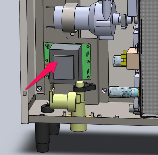
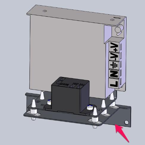
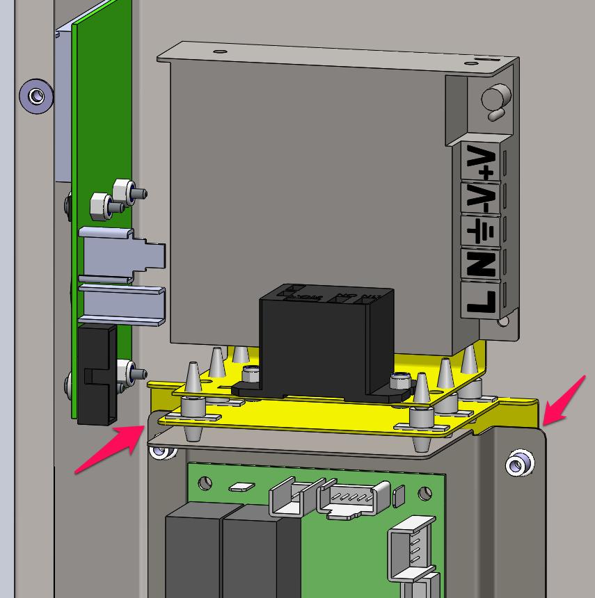
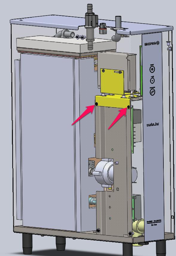
3 Fig 1 Fig 2 Fig 3 Fig 4 Fig 5 Fig 6 UC4-UC10-UC45 Pump Power supply upgrade Page 3 of 9

4 Fig 7 Fig 8 UC4-UC10-UC45 Pump Power supply upgrade Page 4 of 9
5 B) Model UC10 Variants Plug out the machine from mains supply before commencement. Remove the front Service panel as illustrated in Fig 9.0 Remove the old PSU supply from current position. Disconnect and discard the Live & Neutral wires from main PCB. You can cut the cable tie and remove from circuit. Disconnect the positive (red) and negative (black or purple) pump wires from the old power supply ( ) -these wires will attach to the new power supply assembly using their existing spade connections. Position the new PSU on the 6 pillar supports as per Fig 10. Note: There is only one correct orientation so earth cable can reach base. See Fig 10 position and fit. Use the wiring diagram in Fig 8 & 10 to wire the new power supply to the PCB board. Use the piggy back connectors to connect the Live as shown in Fig 8. Ensure the earth cable is connected to the machine body. Please refer to the UC10 Service manual Appendix for your model variant complete wiring diagram if in doubt about any of the wiring circuit. Choose the correct wiring diagram as per machine type, e.g. Ecosmart 5.6kw. Ecoboiler 2.8kw etc etc Replace the front service panel. Machine is now ready for use. UC4-UC10-UC45 Pump Power supply upgrade Page 5 of 9


6 Fig 9 Ensure the PSU is positioned as illustrated Fig 10 UC4-UC10-UC45 Pump Power supply upgrade Page 6 of 9

7 C) Model UC45 Variants Plug out the machine from mains supply before commencement. Remove the front Service panel. Remove the old PSU supply from current position Fig 11. Disconnect and discard the Live & Neutral wires from main PCB. You can cut the cable ties and remove from circuit. Disconnect the positive (red) and negative (black or purple) pump wires from the old power supply ( ) -these wires will attach to the new power supply assembly using their existing spade connections. Position the new PSU on the 6 pillar supports as per Fig 12. Note: There is only one correct orientation so earth cable can reach base. See Fig 12 position and fit. Use the wiring diagram in Fig 13 to wire the new power supply to the PCB board. Use the piggy back connectors to connect the Live as shown in Fig 13. Ensure the earth cable is connected to the machine body. ***If replacing both PSU you will need to remove the spade connector from the right pump PSU live feed (Brown wire) and connect to the live feed of the left PSU as per Fig 13. Cut the spade off*** Please refer to the UC45 Service manual Appendix for your model variant complete wiring diagram if in doubt about any of the wiring circuit. Choose the correct wiring diagram as per machine type, e.g. Ecosmart 5.6kw. Ecoboiler 2.8kw etc etc Replace the front service panel. Machine is now ready for use. Fig 11 UC4-UC10-UC45 Pump Power supply upgrade Page 7 of 9

8 Fig 12 UC4-UC10-UC45 Pump Power supply upgrade Page 8 of 9
9 Fig 13 UC4-UC10-UC45 Pump Power supply upgrade Page 9 of 9
TB Touchscreen software update Revision 1.5, with upgraded PCB Revision 2.2 (P/N K) Topic: JET6, OVERVIEW UPDATE
 Topic: JET6, OVERVIEW UPDATE") Topic: JET6, Touchscreen software update Revision 1.5, with upgraded PCB Revision 2.2 (P/N1600202K) TB No.: 10046 Date: Aug2017 Affected Machines: JET6 Priority: Medium Created By: Gareth Fitzpatrick From
Topic: JET6, Touchscreen software update Revision 1.5, with upgraded PCB Revision 2.2 (P/N1600202K) TB No.: 10046 Date: Aug2017 Affected Machines: JET6 Priority: Medium Created By: Gareth Fitzpatrick From
Phase Loss Protection Upgrade. Phase Loss Protection Upgrade. In this bulletin:
 Phase Loss Protection Upgrade In this bulletin: Introduction... 2 Purpose... 2 General... 2 Applicability... 2 HD3070 Phase Loss Protection Upgrade Kit Parts... 2 Preparation... 4 Install the Phase Loss
IMPORTANT AS YOU REMOVE THE CONNECTORS LABEL THE CONNECTOR WITH THE NAME OF PLUG WITH THE SHARPIE
 TOOLS REQUIRED : small flat head screwdriver no wider than ⅛ or 3mm wide, phillips head screwdriver, 3mm allen wrench, self tapping screws #6 x ½, ¼ hex head driver, electric drill, wire cutters, fine
Upgrading the programmer supply unit of the BeeProg+/BeeProg2 programmer
 Upgrading the 50-0033 programmer supply unit of the BeeProg+/BeeProg2 programmer How-Do-It Manual December 2012 BeeProgX_50-0033_PSU1_upgrade_manual, version 1.31 page 1 Introduction This how-do-it manual
BENSON VARIANTE² TUBULAR HEATER NEW FAN CONTROL/LIMIT STAT RETROFIT NATURAL GAS (G20 I 2 H), PROPANE GAS (G31 I 3 P)
, PROPANE GAS (G31 I 3 P)") Technical Bulletin BENSON VARIANTE² TUBULAR HEATER NEW FAN CONTROL/LIMIT STAT RETROFIT NATURAL GAS (G20 I 2 H), PROPANE GAS (G31 I 3 P) WARNINGS Benson equipment must be installed and maintained in accordance
Technical Bulletin BENSON VARIANTE² TUBULAR HEATER NEW FAN CONTROL/LIMIT STAT RETROFIT NATURAL GAS (G20 I 2 H), PROPANE GAS (G31 I 3 P) WARNINGS Benson equipment must be installed and maintained in accordance
Replacing the Power Supply
 APPENDIX B This appendix includes information on how to replace the power supply for the Cisco AS550XM universal gateway and contains the following sections: Safety Recommendations, page B-1 Required Tools
Installation Guide. Retrofit Kit for USB Ready Intraoral Systems
 Installation Guide Retrofit Kit for USB Ready Intraoral Systems Table of Contents Wall-Mount Retrofit Kit... 2 Introduction... 2 Connecting the Articulating and Horizontal Arm Cables... 2 Installing the
Installing 6 Indexer: PRS Standard Tools
 888-680-4466 ShopBotTools.com Installing 6 Indexer: PRS Standard Tools Copyright 2016 ShopBot Tools, Inc. page 1 Copyright 2016 ShopBot Tools, Inc. page 2 Table of Contents Overview...5 Installing the
Installing Keypad and Backplate
 Installing Keypad and Backplate Fig.1 Positioning of Fixing Holes and Cable Outlet Cable Outlet, Drill Diameter 10mm for Cable Access Remove the back plate, which is fitted to rear of the keypad, using
Digital Keypad Introduction
 K2 Digital Keypad Introduction The K02 uses the latest microprocessor technology to operate door strikes and security systems that require a momentary (timed) or latching dry contact closure. All programming
EMC 10T "CE" Mechanical Upgrade Procedure
 EMC 10T "CE" Mechanical Upgrade Procedure Kit Part Number: 009866-01 This procedure upgrades a non-ce compliant machine to the mechanical requirements of a CE compliant machine. Properly upgraded machines
Installation, Usage and Maintenance Guide for Kit 1
 Installation, Usage and Maintenance Guide for Kit 1 July 2013 WARNING Read this document before installing or using Data East/Sega Speaker Light Mod by Pinballtoppers Improper installation, improper use,
EMC 10/4 "CE" Mechanical Upgrade Procedure
 EMC 10/4 "CE" Mechanical Upgrade Procedure Kit Part Number: 009663-01 This procedure upgrades a non-ce compliant machine to the mechanical requirements of a CE compliant machine. Properly upgraded machines
7" Touch Screen Display
 7" Touch Screen Display Installation Guide Contents Minimum Requirements...1 Select a Location...1 Initial Setup...2 Unboxing...2 Installation...3 Prepare the Panel...3 Install the Mounting Plate...3 Mount
Conect 121 Upgrade. Copyright 2013 Conqueror Design and Engineering Ltd.
 All rights reserved. Any dispute about the use of this software and/or hardware or of these terms and conditions shall be resolved or arbitrated under English Law. Manuals and accompanying documentation
PoE/FPR Kit for Auto-Sync Time Clock. The Auto-Sync Time Clock is a validated time system with a Web interface and auto discovery.
 ASTCPOEK PoE/FPR Kit for Auto-Sync Time Clock The Auto-Sync Time Clock is a validated time system with a Web interface and auto discovery. The ASTCPOEK Kit provides Power over Ethernet with Full Power
E1135C PDU and Pod Upgrade Procedure
 E4030-90010 Rev. B 12/2003 In this Document... Tools Needed, 2 Contents of the Upgrade Kits, 2 Installation Procedures, 4 Verifying the Power Option of the New PDU, 4 Removing the PDU from the Support
FITTING INSTRUCTIONS
 & This option connects a GL3000 or GL3300 console as a channel expander to a second console with just one or two interconnecting cables. Kit Part No: GL3000-SL1 Single option to install SYS-LINK to one
GL2200 MIXING CONSOLE
 GL2200 MIXING CONSOLE SYS-LINK EXPANDER OPTION This option connects a GL2200 console as a channel expander to a second console with just one or two interconnecting cables. Kit GL2200-SL1 = SINGLE Single
Megatouch FORCE Monitor Chassis Board Replacement
 Megatouch FORCE Monitor Chassis Board Replacement Visit the Merit Industries, Inc. Web site http://www.meritind.com merit industries, inc. PM0337-01 Rev C Table of Contents FORCE Classic Monitor Chassis
Prisma II Chassis 56-Port Upgrade Technical Bulletin
 Prisma II Chassis 56-Port Upgrade Technical Bulletin Overview Audience Introduction This technical bulletin applies to all cable system operators and technicians who use the Prisma II Chassis configured
Revised: Page 1
 Brought To You By And Designed By: Revised: 2017-05-07 Page 1 Features Of The Universal PSU Kit: Fits all standard Apple II and /// Power Supply Enclosures. (all parts included, user supplies household
XD Upgrade. HPR130 and HPR260. Field Service Bulletin Revision 1 March, 2010
 XD Upgrade HPR130 and HPR260 Field Service Bulletin 806480 Revision 1 March, 2010 WARNING ELECTRIC SHOCK CAN KILL Disconnect electrical power before performing any maintenance. All work requiring removal
Landmark Upgrade Kit Installation Instructions
 Landmark Upgrade Kit Installation Instructions REMOVING THE LANDMARK BOARD 1 REMOVE POWER FROM UNIT. 2 Disconnect ALL board connections by removing the associated blue blocks (see Figure 1). Include the
CONSOLE CONNECTOR KIT 9501 INSTALLATION INSTRUCTIONS
 CONSOLE CONNECTOR KIT 9501 INSTALLATION INSTRUCTIONS FOR USE WITH: HAMMOND Organ Models L-100, M-100 Series, M-l, M-2, M-3 LESLIE Speaker Models 760, 770, 825 KIT CONTENT Console Connector Assembly 043075
Upgrading a 2U CHP to an i7 Quad Core SBC
 Upgrading a 2U CHP to an i7 Quad Core SBC 1. Parts required: i7 SBC Slim line SATA DVD drive Combined SATA data and power cable for slim-line optical drive Serial port ribbon cable - 9way D male to 10
SRI-02 Speech Recognition Interface
 SRI-02 Speech Recognition Interface Data & Construction Booklet The Speech Recognition Interface SRI-02 allows one to use the SR-07 Speech Recognition Circuit to create speech controlled electrical devices.
Upgrade Instructions Printer Terminal Holder
 Upgrade Instructions 6820 Printer Terminal Holder Instructions Terminal Holder Installation Kit The terminal holder connects INTERMEC R computers to the 6820 Printer. Do these instructions, in the order
TDM To MiniMech conversion ProceDure
 TDM To MiniMech conversion ProceDure (Model 9100 ATM) TDN 07102-00079 Apr 1 2009 CorporATe HeAdquArTers: 522 E. Railroad Street Long Beach, MS 39560 PHONE: (228) 868-1317 FAX: (228) 868-0437 COPYRIGHT
Installation Guide for Mazak Mazatrol M - Plus, M-2, M32, T-Plus, T2
 1 Installation Guide for Mazak Mazatrol M - Plus, M-2, M32, T-Plus, T2 Tsubis Part Number: LCD12-0046 Power Down 1. Power down the controller. 2. Power down the complete machine by turning off the rear
Installing Sentor. Hardware Installation
 Remote base site monitoring and control Installing Sentor Hardware Installation Copyright 2000 Sentor Monitoring Systems Pty Ltd Contents: 1 Introduction... 1 2 Sentor GUI... 2 3 ST3000 Controller... 3
How To Install: C4000 EMV Upgrade Kit
 How To Install: C4000 EMV Upgrade Kit IMPORTANT: Before proceeding with installation please verify you have the current card reader bezel in the kit. Correct bezel will have a small eject pin hole below
INSTALLATION INSTRUCTIONS
 Wired Remote Controller 7 Day Programmable Ductless Systems KSACN0401AAA (High Wall Models) KSACN0501AAA (Ducted/Cassette Models) INSTALLATION INSTRUCTIONS NOTE: Read the entire instruction manual before
ATTENTION: OBSERVE PRECAUTIONS FOR HANDLING ESD-SENSITIVE DEVICES
 Hard Drive Removal IMPORTANT NOTE: If you are replacing a PATA hard drive with a SATA hard drive, please see PATA to SATA Hard Drive Conversion. Hard Drive Identification: To determine whether your hard
LENS REPLACEMENT PROCEDURE
 LCD PROJECTOR LENS MODEL LNS-T31A/W31A LENS REPLACEMENT PROCEDURE NOTE; Lens installation is different in cabinet design (Type A and B). Before installation the lens, check cabinet design and proper installation
The Power Generation Display Unit is available in two sizes as described in the following table:
 Micha www.micha.co.uk Power Generation Display Unit 801309 1. Introduction The Power Generation Display Unit is designed to display the power generated by any Power Generation system but is usually used
Plasma Retrofit Guide Upgrade Kit Installation Instructions
 Upgrade Kit Installation Instructions 1. TMC 3-in-1 Installation 1.1 Unplug the power cable from your CPR800 Control Unit and open the lid. Note The pictures show a NEMA 23 CRP800 Control Unit but the
HQ Pro-Stitcher Hardware Upgrade Installation Instructions 01/15/13
 Getting Started Monitor Styles HQ Pro-Stitcher Hardware Upgrade Installation Instructions 01/15/13 1. Identify the monitor style on your HQ Pro-Stitcher by comparing to the photos at the right. 2. Find
Vector 3D printer complete wire list including extruder PWA listing
 Vector 3D printer complete wire list including extruder PWA listing Conventions Pin numbering for connectors It is normal practice in print circuit board (PCB) layout to denote pin 1 of a PCB mounted connector
WBS HARDWIRED SERIES 4-60KVA MAINTENANCE BYPASS SWITCH
 WBS HARDWIRED SERIES 4-60KVA MAINTENANCE BYPASS SWITCH Man 440 Issue 7 1 1. INTRODUCTION... 3 2. INSTALLATION... 3 2.1 Connection of the Mains Supply... 3 2.2 Connection of the Input to the UPS... 4 2.3
PowerFlex 400 Frame G and H Replacement Procedure for Gate Power Board
 Service Bulletin PowerFlex 400 Frame G and H Replacement Procedure for Gate Power Board Contents This publication provides instructions for replacing the gate power board for PowerFlex 400 Frame G and
DELUXE STEREO AMPLIFIER KIT
 ESSENTIAL INFORMATION BUILD INSTRUCTIONS CHECKING YOUR PCB & FAULT-FINDING MECHANICAL DETAILS HOW THE KIT WORKS CREATE YOUR OWN SPEAKER DOCK WITH THIS DELUXE STEREO AMPLIFIER KIT Version 2.0 Build Instructions
ATTENTION: OBSERVE PRECAUTIONS FOR HANDLING ESD-SENSITIVE DEVICES
 Hard Drive Removal IMPORTANT NOTE: If you are replacing a PATA hard drive with a SATA hard drive, please see PATA to SATA Hard Drive Conversion. Hard Drive Identification: To determine whether your hard
Direct Injection Module
 Note: Indented items indicate parts included in an assembly listed above Part Name/Description Part number Quantity DirectCommand Kit 4100571 1 Module Mounting Hardware Kit 2001354-1 1 Installation Instructions
Installation Instructions
 Installation Instructions Kit Core Upgrade-EMB-B75B Without Modem Kit #22166905 These instructions outline the procedures to install the EMB-B75B motherboard into your existing Computer Core Chassis. There
AC300/AC400 SERIES DYNAMIC BRAKING and ADDITIONAL FORM C RELAY. INSTALLATION INSTRUCTIONS Document Number:
 Minarik Variable Speed AC Motor Drives AC300/AC400 SERIES DYNAMIC BRAKING and ADDITIONAL FORM C RELAY INSTALLATION INSTRUCTIONS Document Number: 250-0297 These instructions apply to models rated: 7.5 25
Instruction Add a second I/O board
 Instruction Add a second I/O board Kit art. No. 472991911 438 9041-81/EN 2013.07.04 Instruction 3 1 Add a second I/O board Contents of the kit Type 2 I/O board P-Bus wire harness D-Bus wire harness Adhesive
Removal and Installation8
 8 Screw Types 8-4 Top Cover Assembly 8-5 Left Hand Cover 8-6 Right Hand Cover 8-10 Front Panel Assembly 8-14 Left Rear Cover 8-15 Right Rear Cover 8-16 Extension Cover (60" Model only) 8-17 Media Lever
FC-25/50DA Main Circuit Board Replacement Product Installation Document
 FC-25/50DA Main Circuit Board Replacement Product Installation Document Document 51875 Rev A 10/12/01 ECN 01-506 This Product Installation Document outlines the replacement of the Main Circuit Board for
INSTALLATION INSTRUCTIONS
 2015 F-150 8 MyTouch factory display 360º Vision System (Kit # AVMS-3618) DUE TO THE COMPLEXITY OF THIS KIT PROFESSIONAL INSTALLATION IS REQUIRED CALIBRATION KIT IS REQUIRED FOR FINAL PROGRAMMING -Must
Ag Leader Technology Insight. Direct Command Installation Spra-Coupe 7000 Series
 Note: Indented items indicate parts included in an assembly listed above. Part Name / Description Part Number Quantity Direct Command Spra-Coupe 7000 Kit 4100531 1 Liquid Product Control Module 4000394
RLN4801 / RLN4802. Accessories. Remote Mount Kit (excluding Cable Kit) Professional Radio
 Professional Radio") RLN4801 / RLN4802 Remote Mount Kit (excluding Cable Kit) Accessories Professional Radio Remote Mount Controlhead Installation! CAUTION: The radio must be disconnected from the power supply before commencing
RLN4801 / RLN4802 Remote Mount Kit (excluding Cable Kit) Accessories Professional Radio Remote Mount Controlhead Installation! CAUTION: The radio must be disconnected from the power supply before commencing
Parts and Accessories Installation Instructions
 Parts and Accessories Installation Instructions TV function retrofit kit BMW 7 Series (E 65 and E 66) These installation instructions are only valid for cars with SA 69 (navigation system) Important information
PIX 515/515E. PIX 515/515E Product Overview CHAPTER
 CHAPTER 4 PIX 515/515E This chapter describes how to install the PIX 515/515E, and includes the following sections: PIX 515/515E Product Overview Installing a PIX 515/515E PIX 515/515E Feature Licenses
Connecting a Cisco Reader Module
 CHAPTER 3 Overview The optional Cisco Reader Module (Figure 3-1) is similar to the Cisco Physical Access Gateway, providing the same ports for Weigand readers and other input and output devices. The Cisco
High Power (15W + 15W) Stereo Amplifier
 Stereo Amplifier") High Power (15W + 15W) Stereo Amplifier Build Instructions Issue 1.0 Build Instructions Before you put any components in the board or pick up the soldering iron, just take a look at the Printed Circuit
High Power (15W + 15W) Stereo Amplifier Build Instructions Issue 1.0 Build Instructions Before you put any components in the board or pick up the soldering iron, just take a look at the Printed Circuit
ZAVIO Outdoor IR Mini Dome. Quick Installation Guide
 ZAVIO Outdoor IR Mini Dome Quick Installation Guide 0 Quick Installation Guide Please follow the installation steps below to set up your IP Camera. Check the package contents with the list below. See P.1
NUR Fresco HiQ 1800 # NUR Fresco HiQ 3200 # 14201
 PRODUCT: PART/ASSEMBLY: NUR Fresco HiQ Motion I/O Delay FCO P/N: 10-0759 ISSUE DATE: DESCRIPTION OF CHANGE: APPLICABLE FOR S/N: 11-Sep-02 Installing a Time Relay Between the 24 VDC and the 5 VDC Motion
BehringerMods.com. Instructions for modification of Behringer SRC analog inputs and outputs
 BehringerMods.com Instructions for modification of Behringer SRC analog inputs and outputs The following instructions will cover the details of fully modifying a unit with analog output and analog input
Installation Instructions
 Installation Instructions Ecast EQ to AMI hardware conversion KIT #26683701 This kit is for use in Ecast EQ jukeboxes. Tools Required #2 Phillips screw driver, #1 Phillips screw driver, Small flat blade
MegaTrak MCU-9000 Harness Wiring
 MegaTrak MCU-9000 Harness Wiring Contents: 1. MCU9000 Connector Pin-Out Schematic 2. MCU9000 Connections when replacing an MCU3000 3. MCU9000 Connections Using 120VAC ( Hot ) Hook Switch (RS485 cable)
INSTRUCTION BULLETIN
 INSTRUCTION BULLETIN No. 9008755 Machine: T16 Published: 03-2011 Rev. 00 NOTE: DO NOT DISCARD the Parts List from the Instruction Bulletin. Place the Parts List in the appropriate place in the machine
Privacy Wall - Power & Data Box (Field Installed) Modular & Hardwire Versions
 Modular & Hardwire Versions") Privacy Wall - Power & Data Box (Field Installed) Modular & Hardwire Versions If you have a problem, question, or request, call your local dealer, or Steelcase Line 1 at 888.STEELCASE (888.783.3522) for
Privacy Wall - Power & Data Box (Field Installed) Modular & Hardwire Versions If you have a problem, question, or request, call your local dealer, or Steelcase Line 1 at 888.STEELCASE (888.783.3522) for
BLUE 3 INSTALLATION GUIDE
 BLUE 3 INSTALLATION GUIDE CATCH Power BLUE 3 Installation manual - Page 1 IMPORTANT This product must be installed by a licensed electrician. This product must be installed according to the AS3000 Australian
RAM Rail Mount Kit RAM 201U 5 Arm RAM 2461U Monitor Mount RAM 235U Base, Double U-Bolt
 DirectCommand Installation Ag Leader Technology Note: Indented items indicate parts included in an assembly listed above Part Name/Description Part Number Quantity DirectCommand Kit 4100852 1 Cable Installation
RAM Rail Mount Kit RAM 201U 5 Arm RAM 2461U Monitor Mount RAM 235U Base, Double U-Bolt
 Note: Indented items indicate parts included in an assembly listed above Part Name/Description Part Number Quantity DirectCommand Kit 4100800 1 Cable Installation Kit 2000901-1 1 Dielectric Grease 2002872
Quicksilver 606 TR-606 CPU Upgrade
 Quicksilver 606 TR-606 CPU Upgrade D650C 128 Installation Guide Social Entropy Electronic Music Instruments TABLE OF CONTENTS WARNINGS... 1 OVERVIEW... 2 WHAT'S IN THE BOX... 3 OPENING THE TR-606 CASE...
With a surface greater than 10 square cm All types including standard alkaline & lithium coin/button style
 Appendix 3 Product End-of-Life Disassembly instructions Product Identification: Marketing Name / Model Description HP Compaq Business Desktop dc5100 Series, HP business desktop PC Small Form Factor version
SCdefault. 900 Installation instructions. Accessories Part No. Group Date Instruction Part No. Replaces :36-26 May
 SCdefault 900 Installation instructions SITdefault Upgrade to Prestige 300 sound system MONTERINGSANVISNING INSTALLATION INSTRUCTIONS MONTAGEANLEITUNG INSTRUCTIONS DE MONTAGE Accessories Part No. Group
Pan-Tilt-Zoom Security Camera
 Security Made Smarter Pan-Tilt-Zoom Security Camera For use with Swann Pro-Series 080p DVRs EN INSTRUCTION MANUAL M080VERE Swann 07 7 5 8 6 4 VIDEO INPUT 4 INPUT OUTPUT VGA RS485 LAN V Step One - Introduction
Navigation interface for Jeep GC 5 RA2 NTV-KIT581
 3950 NW 120 th Ave, Coral Springs, FL 33065 TEL 561-955-9770 FAX 561-955-9760 NNG-Jeep GC Navigation interface for Jeep GC 5 RA2 NTV-KIT581 NNG-JEEP GC Kit Content 5 1 6 4 7 2 3 1. 2. 3. 4. 5. 6. 7. 8.
M-Series 415 & in 1 Elevator Light Curtain. Installation Manual
 M-Series 415 & 405 2 in 1 Elevator Light Curtain Installation Manual Table of contents PRINCIPLE 1 INSTALLATION 2 MOUNTING THE POWER SUPPLY MS721 6 POWER SUPPLY MS721 AND EARTH CONNECTION 8 FUNCTIONAL
NATIONAL CERTIFICATE (VOCATIONAL) ELECTRICAL SYSTEMS AND CONSTRUCTION NQF LEVEL 2 SUPPLEMENTARY EXAMINATION 2010
 ELECTRICAL SYSTEMS AND CONSTRUCTION NQF LEVEL 2 SUPPLEMENTARY EXAMINATION 2010") NATIONAL CERTIFICATE (VOCATIONAL) ELECTRICAL SYSTEMS AND CONSTRUCTION NQF LEVEL 2 SUPPLEMENTARY EXAMINATION 2010 (12041032) 4 March (X-Paper) 09:00 12:00 This question paper consists of 6 pages. (12041032)
NATIONAL CERTIFICATE (VOCATIONAL) ELECTRICAL SYSTEMS AND CONSTRUCTION NQF LEVEL 2 SUPPLEMENTARY EXAMINATION 2010 (12041032) 4 March (X-Paper) 09:00 12:00 This question paper consists of 6 pages. (12041032)
Cat.6/5e UTP Patch Panels with 45 Jack
 Cat.6/5e UTP Patch Panels with 45 Jack Index TOOL KITS TOOL WIRING CONNECTORS LAN/DATACOMM INSTRUMENT MISCELLANEOUS POWER TOOLS FIBER OPTICS MAGNIFICATION & Our Cat.6/5e patch panels are used for high
Additional information for Octopus NET manual Octopus NET Rack. Additional information for Octopus NET manual. Octopus Net Rack
 1 Additional information for Octopus NET manual Octopus Net Rack 2 Table of Contents 1. Classification... 3 2. Delivery Content... 4 3. Expansion... 4 4. Konfigurationsbeispiele:... 4 5. Description oft
QCOLVCZ4M/Z6M SV Series Interface Cable Kit for Z4M and Z6M
 QCOLVCZ4M/Z6M SV Series Interface Cable Kit for Z4M and Z6M The enclosed kit contains all of the parts necessary to connect a Model Z4M or Z6M (ZxM) printer to an external Hand Held Products SV type scanner/verifier.
Fitting An Emulator into the Yamaha AR Organ
 Fitting An Emulator into the Yamaha AR Organ As performed by Les White and Frank Kemplay May 2011 On the upper rear panel remove the top line of 3 screws to allow removal of the top board assemblywhich
VeNICE 2002 VeNICE 2002-PRO Range Rover L Bluetooth Audio Input Module
 VeNICE 2002 VeNICE 2002-PRO Range Rover L322 2002-2005 Bluetooth Audio Input Module Thank you and congratulations for the purchase of the L322 VeNICE Bluetooth module! We are urged to remind you that any
Voice Evacuation Control Panel Main Circuit Board Replacement Product Installation Document
 Voice Evacuation Control Panel Main Circuit Board Replacement Product Installation Document Document 50795 Rev B 10/10/01 ECN 01-507 This Product Installation Document outlines the replacement of the Main
Golf Control Panel Conversion Instructions
 Golf Control Panel Conversion Instructions Document Part #: 040-0079-01 This document describes the steps for upgrading the control panel on an old golf cabinet for use with an EA SPRTS PGA TUR Golf Conversion
TIVO DVR UPGRADE INSTRUCTIONS (#80-HD)
") TIVO DVR UPGRADE INSTRUCTIONS (#80-HD) (c) 2001-2006, weaknees. All rights reserved. Instructions for TwinBreeze HR10-250 DVR Upgrade Bracket/Kit Instructions are available online (in COLOR) at http://www.weaknees.com
TIVO DVR UPGRADE INSTRUCTIONS (#80-HD) (c) 2001-2006, weaknees. All rights reserved. Instructions for TwinBreeze HR10-250 DVR Upgrade Bracket/Kit Instructions are available online (in COLOR) at http://www.weaknees.com
Section. Service & Maintenance. - Core & Hard Disk Drive (HDD) - Amplifier - Monitor - UPS - Dollar Bill Acceptor - Fan Filter G - 1
 - Amplifier - Monitor - UPS - Dollar Bill Acceptor - Fan Filter G - 1") Section G Service & Maintenance - Core & Hard Disk Drive (HDD) - Amplifier - Monitor - UPS - Dollar Bill Acceptor - Fan Filter G - 1 Core Removal Core & HDD 1. Open the door. 2. Perform shutdown procedure.
Section G Service & Maintenance - Core & Hard Disk Drive (HDD) - Amplifier - Monitor - UPS - Dollar Bill Acceptor - Fan Filter G - 1 Core Removal Core & HDD 1. Open the door. 2. Perform shutdown procedure.
InSight Single Implement
 Note: Indented items indicate parts Included in an assembly listed above Part name/description Part Number Quantity DirectCommand 4100544 1 Cable Install Kit 2000901-1 1 Module Mounting Plate Kit 2001358
SNA KIT Assembly Guide
 SNA KIT Assembly Guide Ver 0.8 April 2015 Note: Many references still exist to the SNA Kit s predecessor (NAT Kit). Also, the parts and additional steps used to make the NAT an SNA have not yet been shown
Upgrade Instructions. P/N Revision A. October Printer Terminal Holder * *
 Upgrade Instructions P/N 96-08-0 Revision A October 000 480 Printer Terminal Holder P/N 96-08-0 Revision A *96080* Instructions This terminal holder connects the INTERMEC R 600 Series and 700 Series Computers
T9 EPP KEYPAD FIELD UPGRADE
 T9 EPP KEYPAD FIELD UPGRADE TDN 07103-00237 July 1, 2014 Corporate Headquarters 21405 B Street Long Beach, MS 39560 Phone: (800) 259-6672 Fax: (228) 868-9445 COPYRIGHT NOTICE 2014 Triton. All Rights Reserved.
Seeburg JCU-DEC Kit Convert Your Seeburg DEC Wallbox Into a Jukebox
 Seeburg JCU-DEC Kit Convert Your Seeburg DEC Wallbox Into a Jukebox MP3 Compact Flash Player Coin Operated or Free Play Integrated Power Amplifier Line-Out to External Amplifier Programmable Autoplay IR
Installation Instructions. Ecast Mojo B75B Motherboard Upgrade Kit Kit #
 Installation Instructions Ecast Mojo B75B Motherboard Upgrade Kit Kit #26684501 This kit contains the parts and instruction to install the B75B Motherboard into your Ecast Mojo jukebox. Tools Required
FLOE WIRELESS REMOTE ASSEMBLY INSTRUCTIONS KIT P/N
 FLOE WIRELESS REMOTE ASSEMBLY INSTRUCTIONS KIT P/N 5-0083-00 TOOLS REQUIRED - 3/4" SOCKET - 3/4" WRENCH - /3" WRENCH - PHILLIPS SCREW DRIVER - TORQUE WRENCH INSTRUCTION P/N 6-0083-00 ISSUED: 3//7 SHEET
4100/ VDC Converter Installation Instructions
 4100/4120-0156 8 VDC Converter Installation Instructions Introduction This publication describes the installation procedure for the 8 VDC Converter. Related Documentation Field Wiring Diagram for 4100
Installing the PSU for the S50 and S50N
 Installing the PSU for the S50 and S50N Caution: Use only the power cords supplied with the power supply. Do not supply power to your S50 or S50N system until the power supply and modules have been installed.
Installing a Power over Ethernet injector
 Installing a Power over Ethernet injector AlphaEclipse StreetSmart and RoadStar signs The instructions in this document explain how to install/replace a Power over Ethernet (PoE) injector in a StreetSmart
BuffaloLabs WiFi Lantern Assembly guide version 1
 BuffaloLabs WiFi Lantern Assembly guide version 1 Needed equipment: Solder iron Solder wire Cutter Wire stripper (optional) Hot glue gun Overview of the components (not including USB cable and box panels)
Whitebox TM Developer s Guide
 Whitebox TM Developer s Guide Revision 1.0 April 22, 2016 c 2016 Arx Pax Labs, Inc. 1 Contents 1 Introduction 3 2 Equipment Not Included 3 3 How to Disassemble the Whitebox 4 4 ESC Programming 9 5 Teensy
Upgrading LVDS Cables Instruction Sheet
 Upgrading LVDS Cables Instruction Sheet INTRODUCTION Use the following instructions to replace the LVDS cables in CP2000-M/MR projectors. The new cables are slightly longer in length and allow for better
View Wall Interface. Dynamic Glass INSTALLATION GUIDE. Description. System Requirements. Installation Overview
 Description The solution is a compact, wall-mounted interface used for monitoring and changing the tint levels of View Dynamic Glass. The product leverages 802.11-based Wi-Fi technology for connectivity
Version 1.1. A guide for BLU2 installations.
 BLU2 Installation Guide Optional Image Version 1.1 A guide for BLU2 installations. Table of Contents TABLE OF FIGURES... 3 BEFORE YOU BEGIN... 5 PeopleNet System Installation Manual... 6 BLU2... 6 BLU2
Treadmill Embedded Touch Screen Won t Power Up
 Treadmill Embedded Touch Screen Won t Power Up E-TRe and E-TRxe This document contains the necessary information to troubleshoot a treadmill with an embedded touch screen that will not power up. Follow
Answer Modular Power. Page 1 of Rev V. Power Kits. Change of Height Harness. Receptical Covers
 Answer Modular Power Change of Height Harness Power Kits Receptical Covers NOTE: Unused modular electrical connector openings are not required to be capped. NOTE: The electrician can cut conduit and wire
DirectCommand Installation CASE IH SPX Ag Leader Technology. PN: Rev. E January 2014 Page 1 of 19
 Note: These installation instructions only cover installation on SPX 4420 Sprayers only. For installation on SPX 3230/3330 Sprayers refer to Installation Instructions P/N 2005945. For SPX 4430 refer to