Ternary Spacecraft Board for Maker Faire Roma 2018 Giuseppe Talarico 1/15
|
|
|
- Melissa Short
- 5 years ago
- Views:
Transcription
1 1/15
.")
2 1.0 Introduction In 1840 Thomas Fowler, an English self-taught mathematician, invented a mechanical calculator that used, for the first time, the balanced ternary notation to perform calculations. The Balanced Ternary is a variant of the Base-3 notation in which each digit can be expressed as: Negative Zero Positive that is: -, 0, + (to Fowler). In 1997 drawings of this machine were found, executed in 1840 by the great mathematician: Augustus De Morgan. In the figure a modern realization printed in 3D based on these drawings. In 2018 a question arises spontaneously: are we ready to concretely use the balanced ternary? The project illustrated here with the implementation of the All Ternary Monadic Functions Generator Board and, above all, with Ternary Spacecraft Board proposes to make a small contribution to the study and to the full understanding of the Ternary Balanced Logic. 2/15
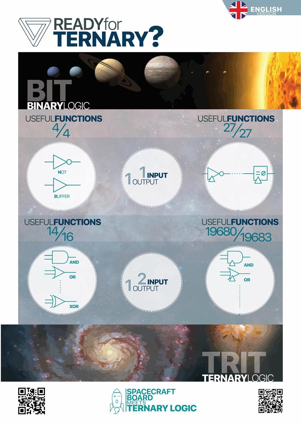
3 2.0 Ternary Logic: a "spacecraft" to explore it. The board design called Ternary Spacecraft was born with the aim of providing a tool to explore what will henceforth be referred to as the "Galaxy" of Ternary Logic. It consists of two parts: a hardware one and a software one. Everything started, in the last months, from the following two articles: Appunti Logica Ternaria Monadic and Diadic Ternary Logic Simulation Results published on my website back in In the Binary system, all the logic functions with one input and one output (monadic functions) are: 2 ^ 2 = 4, as clearly shown in the table below: x f0(x) f1(x) f2(x) f3(x) Among the four monadic functions, only one of them, f1 (x), leads to an elementary logic gate commonly used in the design of digital boards: the NOT. The functions with two inputs and one output (dyadic functions) are instead: 2 ^ 4 = 16, as clearly shown in the table below: x y Among the 16 dyadic functions, six of them lead to usable elementary logic gates: AND [f8 (x, y)], NAND [f7 (x, y)], OR [f14 (x, y)], NOR [f1 (x, y)], XOR [f6 (x, y)], XNOR [f9 (x, y)]. If the logical dyadic functions are implemented with mux then all four monadic functions are used! 3/15
4 Things in the ternary system are slightly different: Number of monadic functions: 3 ^ 3 = 27. Number of dyadic functions: 3 ^ 9 = 19'683 (incredibly high number!) It is easy to assume that nobody has ever ventured into the complete exploration of such a large number of functions, also due to the lack, to date, of commercially available components able to operate on three levels. In this galaxy of possible components, most of them have neither a symbol nor a name. The Ternary Spacecraft, which can be interfaced with either Arduino or Raspberry or any other system equipped with I2C, allows you to generate and explore, thanks to the use of an oscilloscope: the 27 ternary logic gates with one input and one output; the 19'683 gates with two entrances and one exit. Ultimately, the card creates a "Programmable Universal Ternary Dyadic Logic Gate". It consists essentially of a 9: 1 mux, made from four Mux 3: 1, of nine Trit generators that feed the nine inputs of the first level mux 3: 1 and two additional Trit generators to realize two possible ternary signals to be sent to the inputs of the dyadic gate. By programming, from time to time, the ternary truth table of the logic gate (inputs of the Mux) it is possible to obtain all the approximately twenty thousand logical gates mentioned above. Eventually, by appropriately programming the input ternary signals, it is possible to display and study the output waveforms (from which to obtain useful information for a possible use of them in the future design of circuit boards in ternary logic). An entire computer can be made with only MUXes. In fact, the latter are able to realize any truth table and therefore any combinational logic function. Moreover, the sequential digital circuits present in each computer are obtained starting from the combinational circuits. 3.0 The Two-way Binary MUX Let s start with the operation of a simple 2: 1 binary Mux. It can be compared to a twoposition electro-mechanical selector. The "y" output is obtained by manually selecting one of the two possible inputs. In Mux 2: 1 the selection of the input bit, which is output (device output), is obtained through another selection bit "x" (which actually forms the device input). The two bits present at the inputs of the mux "I0", "I1" make the column of a Truth Table with only two lines. Ultimately, a Mux 2: 1 realizes a monadic device, that is with an input and an output, whose operation is regulated by a truth table consisting of a column and two lines. 4/15
5 In terms of binary algebra, the output of the mux has the following logical expression: y = (x * I0) + (x * I1) It is therefore an OR with two inputs, in turn made up of two dyadic AND whose inputs are: x, I0 for the first and x, I1 for the second. A mux can also be made from electronic switches and this is the way used to make the Ternary Spacecraft. As already mentioned, in the monadic binary case all the possible truth tables are four: 2 ^ (Number of Mux Input Bits). Ultimately, by imposing one of the four possible combinations as input to the mux it is possible to obtain one of the following four logical functions: Contradiction Buffer Not Tautology (always output at "0" whatever the value of the input) (Output equal to the input) (Input negation output) (always output at "1" whatever the value of the input) That is, in terms of truth tables: x f0(x) f1(x) f2(x) f3(x) The function f0 (x) always returns 0 (false) and the function f3 (x) always returns 1 (true), regardless of the value of the input symbol. The function f2 (x) returns the same value as the input symbol and therefore is called the Identity or Buffer function. The function f1 (x) returns the negated of the input value and is the only non-trivial of the four. The function f1 (x) is called NOT (logical negation): f1(x) = NOT(x) The binary values of the four truth tables are nothing more than the two-bit binary count from zero to three. The number assigned to each function corresponds to the binary value of the two bits in the table. 5/15
6 The order of the columns of the four tables is completely arbitrary, so they can be arranged as follows: x f-2(x) f-1(x) f0(x) f1(x) The binary values are arranged according to the two's complement notation. The following formula applies to the table as follows: fi (x) = NOT [f-i-1 (x)] with i in [0,1] This expression leads to formulating an interesting property that applies to the whole table: "Half of the table is obtained by complementing the other half". This implies that it is enough to study half the functions, the others will simply be the same but complemented. What for the binary system and especially for the monadic functions is more of a curiosity, for the ternary functions its application is definitely more interesting. 3.1 The Binary Mux 4:1 All sixteen possible two-input binary functions are shown in the table below, adopting the two-complement representation. At the top of each column is shown the subscript of the dyadic function: fi (x, y) with i = [- 8.7] x y The following formula applies to the table as follows: fi (x,y) = NOT[ f-i-1 (x,y) ] con i in [-8,7] As the highlights also suggest, half the table is obtained complementing, column by column, the other half. 6/15
 the NAND function, if x = 1, we have: f7 (1, y) = NOT (y) Being f1 (x, y) the function NOR, if x = 0, we have: f1 (0, y) = NOT (y) Since f6 (x, y) the function XOR, if x")
7 Some notable features: the function of index -2, that is: f-2 (x, y), is: x OR y the function of index -8, that is: f-8 (x, y), is: x AND y the function of index 6, that is: f6 (x, y), is: x XOR y Furthermore: Since f7 (x, y) the NAND function, if x = 1, we have: f7 (1, y) = NOT (y) Being f1 (x, y) the function NOR, if x = 0, we have: f1 (0, y) = NOT (y) Since f6 (x, y) the function XOR, if x = 1, we have: f6 (1, y) = NOT (y) Notice also that: f3 (x, y) = NOT (x), for each y f-4 (x, y) = x, for each y thus, for what has been said before: f-4 (x, y) = NOT [f3 (x, y)] = NOT [NOT (x)] = x The mux 4: 1 allows to select (send in "output") a binary value between four, thanks to two inputs (binary signals) of selection "x" and "y" that make up the two true inputs of the dyadic device. The following figure shows the realization of such a device starting from three monadic 2: 1 muxes. Binary Dyadic Gate The previous scheme suggests that any binary dyadic function can be obtained starting from two monadic functions. The signal y selects from time to time which of the two monadic functions goes out, while the signal x has already selected which of the two possible monadic binary values, for both mux first level, they will form the inputs of the second level mux. This two-level mux model will come in handy later when we talk about the 9: 1 mux ternary. 7/15
.")
8 4.0 The Ternary Mux 3:1 The 3: 1 mux has 3 trit (or 1 Tribble) configuration, a selection Trit and a ternary output (Trit). Its truth table: a c 1 I- 0 I0 1 I+ 8/15
9 The set of the 27 ternary monadic functions can be represented by the following truth tables, combined in a single one: X (i=) D C B A A B C D The function index, which in decimal would be i = [ ], is here represented with the symbols in balanced eptaventesimal: i = [D, D]. x represents the input Trit, while fi (x) represents the output Trit of the monadic gate. [I +, I0, I-] represents the generic configuration Tribble of the ternary monadic gate (the set of three Trit is called Tribble). In this case, observing the table, one has the following property: fi (x) = NOT [f-i (x)] The index 0 function, called Unknown, divides the table into two. The two parts are the inverted copy of the other (note the colors). The index D function is called Contradiction. The index D function is called Tautology. All three functions mentioned do not translate into useful devices, but are used in the implementation of dyadic functions with mux! The Ternary Spacecraft board has three Monadic outputs: MonOut+ MonOut0 MonOutprogrammable and each can generate all 27 functions. Eventually, configuring via software, the three mux of the first level with the same value of Tribble, the Dyadic output is downgraded to the Monadic output of the input signal "a", independently from the signal of "b". 9/15

10 The following is the block diagram of the board:: All Ternary Monadic Functions Generator. The diagram shown above has been submitted to the selection of the Maker Faire Rome /15
11 4.1 The Ternary Mux 9:1 The 9: 1 mux has 9 trit (1 Tryte) configuration, two selection Trit and a ternary output (Trit). The truth table of the ternary 9: 1 MUX is as follows: a b c=f(a,b) 1 1 I I I I0-0 0 I I I I I++ 11/15

12 5.0 Ternary Spacecraft Board Block Diagram The following board diagram shows the design and implementation made for the Maker Faire Rome /15
13 5.1 Optical Interface with Raspberry Being the Ternary Spacecraft a "tweakable" board where to configure and/or display the ternary functions, an optical interface has been added to the design to safeguard the hardware integrity of the Raspberry or of the Arduino connected. Otherwise, an accidental short, even temporary, could have led to the failure of the I/O ports of the aforementioned devices. 5.2 Trit Generators The use of a DG 403, which consists of four analog electronic switches, allows to generate a trit. On the card there are nine Trit Generators to drive the dyadic port, that is to configure the nine ternary inputs of the 9: 1 mux, plus two more for the generation of the real ternary inputs of the dyadic device. Two I/O expansion circuits via the I2C standard interface are used to drive the DG403 selection inputs. Basically, a Bit-Trit decoder is implemented: Bit Trit Ternary Dual Mux The Ternary Dual Mux allows the implementation of the "Programmable Universal Ternary Gate" or a 9: 1 mux ternary, through the adoption of four 3: 1 mux ternaries. The scheme is that of two-level muxes. 5.4 Generation of input signals "a" and "b" The Mux 9:1 input signals "a" and "b" can be provided from the two special trit generators on-board or from the outside. The hardware arrangement takes place through two specially made straps. Connecting INPUT_a with Tsignal_a and INPUT_b with Tsignal_b the signals come from within the board and are generated via software. 13/15

14 6.0 Ternary-Binary Compatibility If the generation of 1 is blocked by software, the board creates a "Universal Programmable Binary Gate" with which to obtain all 16 dyadic functions and 4 monadic ones. Both in Input and Output the signals assume the two classical values [0,1]. The following figure shows the board "downgrading": If instead, no "0" is ever generated by software, the board works in binary mode with non-standard levels, the extreme ones of the ternary. This mode has been called "binary mode PM" (PlusMinus). 14/15


15 7.0 Ternary Spacecraft Software The configuration and operating software of the board has been totally developed in Python and runs on a Raspberry Pi v2 or v3. It allows you to control both the first boards created: the "All Ternary Monadic Functions Generator Board" and the second called "Ternary Spacecraft". 8.0 Contacts Official Maker Faire project link: giustala@gmail.com 15/15
LAB #1 BASIC DIGITAL CIRCUIT
 LAB #1 BASIC DIGITAL CIRCUIT OBJECTIVES 1. To study the operation of basic logic gates. 2. To build a logic circuit from Boolean expressions. 3. To introduce some basic concepts and laboratory techniques
Logic Gates and Boolean Algebra ENT263
 Logic Gates and Boolean Algebra ENT263 Logic Gates and Boolean Algebra Now that we understand the concept of binary numbers, we will study ways of describing how systems using binary logic levels make
(Refer Slide Time 3:31)
") Digital Circuits and Systems Prof. S. Srinivasan Department of Electrical Engineering Indian Institute of Technology Madras Lecture - 5 Logic Simplification In the last lecture we talked about logic functions
Digital Circuits and Systems Prof. S. Srinivasan Department of Electrical Engineering Indian Institute of Technology Madras Lecture - 5 Logic Simplification In the last lecture we talked about logic functions
Combinational Circuits
 Combinational Circuits Combinational circuit consists of an interconnection of logic gates They react to their inputs and produce their outputs by transforming binary information n input binary variables
COMBINATIONAL LOGIC CIRCUITS
 COMBINATIONAL LOGIC CIRCUITS 4.1 INTRODUCTION The digital system consists of two types of circuits, namely: (i) Combinational circuits and (ii) Sequential circuits A combinational circuit consists of logic
(Refer Slide Time 6:48)
") Digital Circuits and Systems Prof. S. Srinivasan Department of Electrical Engineering Indian Institute of Technology Madras Lecture - 8 Karnaugh Map Minimization using Maxterms We have been taking about
Digital Circuits and Systems Prof. S. Srinivasan Department of Electrical Engineering Indian Institute of Technology Madras Lecture - 8 Karnaugh Map Minimization using Maxterms We have been taking about
DIGITAL CIRCUIT LOGIC UNIT 9: MULTIPLEXERS, DECODERS, AND PROGRAMMABLE LOGIC DEVICES
 DIGITAL CIRCUIT LOGIC UNIT 9: MULTIPLEXERS, DECODERS, AND PROGRAMMABLE LOGIC DEVICES 1 Learning Objectives 1. Explain the function of a multiplexer. Implement a multiplexer using gates. 2. Explain the
ECE 2030B 1:00pm Computer Engineering Spring problems, 5 pages Exam Two 10 March 2010
 Instructions: This is a closed book, closed note exam. Calculators are not permitted. If you have a question, raise your hand and I will come to you. Please work the exam in pencil and do not separate
1. Mark the correct statement(s)
") 1. Mark the correct statement(s) 1.1 A theorem in Boolean algebra: a) Can easily be proved by e.g. logic induction b) Is a logical statement that is assumed to be true, c) Can be contradicted by another
1. Mark the correct statement(s) 1.1 A theorem in Boolean algebra: a) Can easily be proved by e.g. logic induction b) Is a logical statement that is assumed to be true, c) Can be contradicted by another
Chapter 4. Combinational Logic
 Chapter 4. Combinational Logic Tong In Oh 1 4.1 Introduction Combinational logic: Logic gates Output determined from only the present combination of inputs Specified by a set of Boolean functions Sequential
DLD VIDYA SAGAR P. potharajuvidyasagar.wordpress.com. Vignana Bharathi Institute of Technology UNIT 3 DLD P VIDYA SAGAR
 DLD UNIT III Combinational Circuits (CC), Analysis procedure, Design Procedure, Combinational circuit for different code converters and other problems, Binary Adder- Subtractor, Decimal Adder, Binary Multiplier,
Digital Circuits 1: Binary, Boolean, and Logic
 Digital Circuits 1: Binary, Boolean, and Logic Created by Dave Astels Last updated on 2018-03-22 04:13:46 PM UTC Guide Contents Guide Contents Introduction Number systems Decimal: base 10 Binary Octal
Combinational Circuits
 Combinational Circuits Jason Filippou CMSC250 @ UMCP 06-02-2016 ason Filippou (CMSC250 @ UMCP) Circuits 06-02-2016 1 / 1 Outline ason Filippou (CMSC250 @ UMCP) Circuits 06-02-2016 2 / 1 Hardware design
Logic, Words, and Integers
 Computer Science 52 Logic, Words, and Integers 1 Words and Data The basic unit of information in a computer is the bit; it is simply a quantity that takes one of two values, 0 or 1. A sequence of k bits
Midterm Exam Review. CS 2420 :: Fall 2016 Molly O'Neil
 Midterm Exam Review CS 2420 :: Fall 2016 Molly O'Neil Midterm Exam Thursday, October 20 In class, pencil & paper exam Closed book, closed notes, no cell phones or calculators, clean desk 20% of your final
1. Draw general diagram of computer showing different logical components (3)
") Tutorial 1 1. Draw general diagram of computer showing different logical components (3) 2. List at least three input devices (1.5) 3. List any three output devices (1.5) 4. Fill the blank cells of the
Tutorial 1 1. Draw general diagram of computer showing different logical components (3) 2. List at least three input devices (1.5) 3. List any three output devices (1.5) 4. Fill the blank cells of the
MODULE 5 - COMBINATIONAL LOGIC
 Introduction to Digital Electronics Module 5: Combinational Logic 1 MODULE 5 - COMBINATIONAL LOGIC OVERVIEW: For any given combination of input binary bits or variables, the logic will have a specific
Chapter 2: Combinational Systems
 Uchechukwu Ofoegbu Chapter 2: Combinational Systems Temple University Adapted from Alan Marcovitz s Introduction to Logic and Computer Design Riddle Four switches can be turned on or off. One is the switch
Bits, Words, and Integers
 Computer Science 52 Bits, Words, and Integers Spring Semester, 2017 In this document, we look at how bits are organized into meaningful data. In particular, we will see the details of how integers are
Principles of Digital Techniques PDT (17320) Assignment No State advantages of digital system over analog system.
 Assignment No State advantages of digital system over analog system.") Assignment No. 1 1. State advantages of digital system over analog system. 2. Convert following numbers a. (138.56) 10 = (?) 2 = (?) 8 = (?) 16 b. (1110011.011) 2 = (?) 10 = (?) 8 = (?) 16 c. (3004.06)
Assignment No. 1 1. State advantages of digital system over analog system. 2. Convert following numbers a. (138.56) 10 = (?) 2 = (?) 8 = (?) 16 b. (1110011.011) 2 = (?) 10 = (?) 8 = (?) 16 c. (3004.06)
Department of Electrical Engineering McGill University ECSE 221 Introduction to Computer Engineering Assignment 2 Combinational Logic
 Department of Electrical Engineering McGill University ECSE 221 Introduction to Computer Engineering Assignment 2 Combinational Logic Question 1: Due October 19 th, 2009 A convenient shorthand for specifying
COMP combinational logic 1 Jan. 18, 2016
 In lectures 1 and 2, we looked at representations of numbers. For the case of integers, we saw that we could perform addition of two numbers using a binary representation and using the same algorithm that
END-TERM EXAMINATION
 (Please Write your Exam Roll No. immediately) END-TERM EXAMINATION DECEMBER 2006 Exam. Roll No... Exam Series code: 100919DEC06200963 Paper Code: MCA-103 Subject: Digital Electronics Time: 3 Hours Maximum
Injntu.com Injntu.com Injntu.com R16
 1. a) What are the three methods of obtaining the 2 s complement of a given binary (3M) number? b) What do you mean by K-map? Name it advantages and disadvantages. (3M) c) Distinguish between a half-adder
UNCA CSCI 255 Exam 1 Spring February, This is a closed book and closed notes exam. It is to be turned in by 1:45 PM.
 UNCA CSCI 255 Exam 1 Spring 2017 27 February, 2017 This is a closed book and closed notes exam. It is to be turned in by 1:45 PM. Communication with anyone other than the instructor is not allowed during
ECE 2030D Computer Engineering Spring problems, 5 pages Exam Two 8 March 2012
 Instructions: This is a closed book, closed note exam. Calculators are not permitted. If you have a question, raise your hand and I will come to you. Please work the exam in pencil and do not separate
Computer Organization and Levels of Abstraction
 Computer Organization and Levels of Abstraction Announcements Today: PS 7 Lab 8: Sound Lab tonight bring machines and headphones! PA 7 Tomorrow: Lab 9 Friday: PS8 Today (Short) Floating point review Boolean
LECTURE 4. Logic Design
 LECTURE 4 Logic Design LOGIC DESIGN The language of the machine is binary that is, sequences of 1 s and 0 s. But why? At the hardware level, computers are streams of signals. These signals only have two
Introduction to Boolean logic and Logical Gates
 Introduction to Boolean logic and Logical Gates Institute of Statistics Fall 2014 We saw the importance of the binary number system for data representation in a computer system. We ll see that the construction
Digital Logic Design Exercises. Assignment 1
 Assignment 1 For Exercises 1-5, match the following numbers with their definition A Number Natural number C Integer number D Negative number E Rational number 1 A unit of an abstract mathematical system
Primitive Computer Functions
 Primitive Computer Functions Basic computer devices are currently binary switching devices. These devices are often called logic devices because their switching behavior can be described by logic or truth
Combinational Logic. Prof. Wangrok Oh. Dept. of Information Communications Eng. Chungnam National University. Prof. Wangrok Oh(CNU) 1 / 93
 1 / 93") Combinational Logic Prof. Wangrok Oh Dept. of Information Communications Eng. Chungnam National University Prof. Wangrok Oh(CNU) / 93 Overview Introduction 2 Combinational Circuits 3 Analysis Procedure
Combinational Logic Prof. Wangrok Oh Dept. of Information Communications Eng. Chungnam National University Prof. Wangrok Oh(CNU) / 93 Overview Introduction 2 Combinational Circuits 3 Analysis Procedure
Digital Systems. John SUM Institute of Technology Management National Chung Hsing University Taichung, ROC. December 6, 2012
 Digital Systems John SUM Institute of Technology Management National Chung Hsing University Taichung, ROC December 6, 2012 Contents 1 Logic Gates 3 1.1 Logic Gate............................. 3 1.2 Truth
COMPUTER SIMULATION OF COMPLEX SYSTEMS USING AUTOMATA NETWORKS K. Ming Leung
 POLYTECHNIC UNIVERSITY Department of Computer and Information Science COMPUTER SIMULATION OF COMPLEX SYSTEMS USING AUTOMATA NETWORKS K. Ming Leung Abstract: Computer simulation of the dynamics of complex
R07
 www..com www..com SET - 1 II B. Tech I Semester Supplementary Examinations May 2013 SWITCHING THEORY AND LOGIC DESIGN (Com. to EEE, EIE, BME, ECC) Time: 3 hours Max. Marks: 80 Answer any FIVE Questions
Review. EECS Components and Design Techniques for Digital Systems. Lec 05 Boolean Logic 9/4-04. Seq. Circuit Behavior. Outline.
 Review EECS 150 - Components and Design Techniques for Digital Systems Lec 05 Boolean Logic 94-04 David Culler Electrical Engineering and Computer Sciences University of California, Berkeley Design flow
Boolean Algebra and Logic Gates
 Boolean Algebra and Logic Gates Binary logic is used in all of today's digital computers and devices Cost of the circuits is an important factor Finding simpler and cheaper but equivalent circuits can
Propositional Calculus. Math Foundations of Computer Science
 Propositional Calculus Math Foundations of Computer Science Propositional Calculus Objective: To provide students with the concepts and techniques from propositional calculus so that they can use it to
EXPERIMENT #8: BINARY ARITHMETIC OPERATIONS
 EE 2 Lab Manual, EE Department, KFUPM EXPERIMENT #8: BINARY ARITHMETIC OPERATIONS OBJECTIVES: Design and implement a circuit that performs basic binary arithmetic operations such as addition, subtraction,
Gate Level Minimization Map Method
 Gate Level Minimization Map Method Complexity of hardware implementation is directly related to the complexity of the algebraic expression Truth table representation of a function is unique Algebraically
Designing Information Devices and Systems II Spring 2018 J. Roychowdhury and M. Maharbiz Discussion 1A
 EEC 16B esigning Information evices and ystems II pring 2018 J. Roychowdhury and M. Maharbiz iscussion 1A 1 igit Bases (N) p is used to indicate that the number N is expressed in base p. For example, (N)
COMPUTER ARCHITECTURE AND ORGANIZATION Register Transfer and Micro-operations 1. Introduction A digital system is an interconnection of digital
 Register Transfer and Micro-operations 1. Introduction A digital system is an interconnection of digital hardware modules that accomplish a specific information-processing task. Digital systems vary in
HANSABA COLLEGE OF ENGINEERING & TECHNOLOGY (098) SUBJECT: DIGITAL ELECTRONICS ( ) Assignment
 SUBJECT: DIGITAL ELECTRONICS ( ) Assignment") Assignment 1. What is multiplexer? With logic circuit and function table explain the working of 4 to 1 line multiplexer. 2. Implement following Boolean function using 8: 1 multiplexer. F(A,B,C,D) = (2,3,5,7,8,9,12,13,14,15)
Assignment 1. What is multiplexer? With logic circuit and function table explain the working of 4 to 1 line multiplexer. 2. Implement following Boolean function using 8: 1 multiplexer. F(A,B,C,D) = (2,3,5,7,8,9,12,13,14,15)
Scheme G. Sample Test Paper-I
 Sample Test Paper-I Marks : 25 Times:1 Hour 1. All questions are compulsory. 2. Illustrate your answers with neat sketches wherever necessary. 3. Figures to the right indicate full marks. 4. Assume suitable
CS Bootcamp Boolean Logic Autumn 2015 A B A B T T T T F F F T F F F F T T T T F T F T T F F F
 1 Logical Operations 1.1 And The and operator is a binary operator, denoted as, &,, or sometimes by just concatenating symbols, is true only if both parameters are true. A B A B F T F F F F The expression
Designing Information Devices and Systems II Fall 2017 Miki Lustig and Michel Maharbiz Discussion 1B
 EEC 16B esigning Information evices and ystems II Fall 2017 Miki Lustig and Michel Maharbiz iscussion 1B igit Bases (N) p is used to indicate that the number N is expressed in base p. For example, (N)
ECE 331: N0. Professor Andrew Mason Michigan State University. Opening Remarks
 ECE 331: N0 ECE230 Review Professor Andrew Mason Michigan State University Spring 2013 1.1 Announcements Opening Remarks HW1 due next Mon Labs begin in week 4 No class next-next Mon MLK Day ECE230 Review
DE Solution Set QP Code : 00904
 DE Solution Set QP Code : 00904 1. Attempt any three of the following: 15 a. Define digital signal. (1M) With respect to digital signal explain the terms digits and bits.(2m) Also discuss active high and
Computer Organization and Levels of Abstraction
 Computer Organization and Levels of Abstraction Announcements PS8 Due today PS9 Due July 22 Sound Lab tonight bring machines and headphones! Binary Search Today Review of binary floating point notation
Chapter 2 Basic Logic Circuits and VHDL Description
 Chapter 2 Basic Logic Circuits and VHDL Description We cannot solve our problems with the same thinking we used when we created them. ----- Albert Einstein Like a C or C++ programmer don t apply the logic.
Binary Adders: Half Adders and Full Adders
 Binary Adders: Half Adders and Full Adders In this set of slides, we present the two basic types of adders: 1. Half adders, and 2. Full adders. Each type of adder functions to add two binary bits. In order
Software and Hardware
 Software and Hardware Numbers At the most fundamental level, a computer manipulates electricity according to specific rules To make those rules produce something useful, we need to associate the electrical
Objectives: 1. Design procedure. 2. Fundamental circuits. 1. Design procedure
 Objectives: 1. Design procedure. 2. undamental circuits. 1. Design procedure Design procedure has five steps: o Specification. o ormulation. o Optimization. o Technology mapping. o Verification. Specification:
Combinational Logic II
 Combinational Logic II Ranga Rodrigo July 26, 2009 1 Binary Adder-Subtractor Digital computers perform variety of information processing tasks. Among the functions encountered are the various arithmetic
VALLIAMMAI ENGINEERING COLLEGE. SRM Nagar, Kattankulathur DEPARTMENT OF ELECTRONICS AND COMMUNICATION ENGINEERING EC6302 DIGITAL ELECTRONICS
 VALLIAMMAI ENGINEERING COLLEGE SRM Nagar, Kattankulathur-603 203 DEPARTMENT OF ELECTRONICS AND COMMUNICATION ENGINEERING EC6302 DIGITAL ELECTRONICS YEAR / SEMESTER: II / III ACADEMIC YEAR: 2015-2016 (ODD
BOOLEAN ALGEBRA. Logic circuit: 1. From logic circuit to Boolean expression. Derive the Boolean expression for the following circuits.
 COURSE / CODE DIGITAL SYSTEMS FUNDAMENTAL (ECE 421) DIGITAL ELECTRONICS FUNDAMENTAL (ECE 422) BOOLEAN ALGEBRA Boolean Logic Boolean logic is a complete system for logical operations. It is used in countless
Chapter Three. Digital Components
 Chapter Three 3.1. Combinational Circuit A combinational circuit is a connected arrangement of logic gates with a set of inputs and outputs. The binary values of the outputs are a function of the binary
Chapter 2 Boolean algebra and Logic Gates
 Chapter 2 Boolean algebra and Logic Gates 2. Introduction In working with logic relations in digital form, we need a set of rules for symbolic manipulation which will enable us to simplify complex expressions
Mark Redekopp, All rights reserved. EE 352 Unit 8. HW Constructs
 EE 352 Unit 8 HW Constructs Logic Circuits Combinational logic Perform a specific function (mapping of 2 n input combinations to desired output combinations) No internal state or feedback Given a set of
Chapter 2: Universal Building Blocks. CS105: Great Insights in Computer Science
 Chapter 2: Universal Building Blocks CS105: Great Insights in Computer Science Homework 1 It is now available on our website. Answer questions in Word or any text editor and upload it via sakai. No paper
ECE 2020B Fundamentals of Digital Design Spring problems, 6 pages Exam Two Solutions 26 February 2014
 Problem 1 (4 parts, 21 points) Encoders and Pass Gates Part A (8 points) Suppose the circuit below has the following input priority: I 1 > I 3 > I 0 > I 2. Complete the truth table by filling in the input
2008 The McGraw-Hill Companies, Inc. All rights reserved.
 28 The McGraw-Hill Companies, Inc. All rights reserved. 28 The McGraw-Hill Companies, Inc. All rights reserved. All or Nothing Gate Boolean Expression: A B = Y Truth Table (ee next slide) or AB = Y 28
QUESTION BANK FOR TEST
 CSCI 2121 Computer Organization and Assembly Language PRACTICE QUESTION BANK FOR TEST 1 Note: This represents a sample set. Please study all the topics from the lecture notes. Question 1. Multiple Choice
IT 201 Digital System Design Module II Notes
 IT 201 Digital System Design Module II Notes BOOLEAN OPERATIONS AND EXPRESSIONS Variable, complement, and literal are terms used in Boolean algebra. A variable is a symbol used to represent a logical quantity.
Basic Arithmetic (adding and subtracting)
") Basic Arithmetic (adding and subtracting) Digital logic to show add/subtract Boolean algebra abstraction of physical, analog circuit behavior 1 0 CPU components ALU logic circuits logic gates transistors
Basic Arithmetic (adding and subtracting) Digital logic to show add/subtract Boolean algebra abstraction of physical, analog circuit behavior 1 0 CPU components ALU logic circuits logic gates transistors
Boolean Algebra. BME208 Logic Circuits Yalçın İŞLER
 Boolean Algebra BME28 Logic Circuits Yalçın İŞLER islerya@yahoo.com http://me.islerya.com 5 Boolean Algebra /2 A set of elements B There exist at least two elements x, y B s. t. x y Binary operators: +
Chapter 3. Boolean Algebra and Digital Logic
 Chapter 3 Boolean Algebra and Digital Logic Chapter 3 Objectives Understand the relationship between Boolean logic and digital computer circuits. Learn how to design simple logic circuits. Understand how
BOOLEAN ALGEBRA AND CIRCUITS
 UNIT 3 Structure BOOLEAN ALGEBRA AND CIRCUITS Boolean Algebra and 3. Introduction 3. Objectives 3.2 Boolean Algebras 3.3 Logic 3.4 Boolean Functions 3.5 Summary 3.6 Solutions/ Answers 3. INTRODUCTION This
REGISTER TRANSFER AND MICROOPERATIONS
 1 REGISTER TRANSFER AND MICROOPERATIONS Register Transfer Language Register Transfer Bus and Memory Transfers Arithmetic Microoperations Logic Microoperations Shift Microoperations Arithmetic Logic Shift
60-265: Winter ANSWERS Exercise 4 Combinational Circuit Design
 60-265: Winter 2010 Computer Architecture I: Digital Design ANSWERS Exercise 4 Combinational Circuit Design Question 1. One-bit Comparator [ 1 mark ] Consider two 1-bit inputs, A and B. If we assume that
Combinational Logic with MSI and LSI
 1010101010101010101010101010101010101010101010101010101010101010101010101010101010 1010101010101010101010101010101010101010101010101010101010101010101010101010101010 1010101010101010101010101010101010101010101010101010101010101010101010101010101010
2. BOOLEAN ALGEBRA 2.1 INTRODUCTION
 2. BOOLEAN ALGEBRA 2.1 INTRODUCTION In the previous chapter, we introduced binary numbers and binary arithmetic. As you saw in binary arithmetic and in the handling of floating-point numbers, there is
EE292: Fundamentals of ECE
 EE292: Fundamentals of ECE Fall 2012 TTh 10:00-11:15 SEB 1242 Lecture 22 121115 http://www.ee.unlv.edu/~b1morris/ee292/ 2 Outline Review Binary Number Representation Binary Arithmetic Combinatorial Logic
 Get Free notes at Module-I One s Complement: Complement all the bits.i.e. makes all 1s as 0s and all 0s as 1s Two s Complement: One s complement+1 SIGNED BINARY NUMBERS Positive integers (including zero)
Topics. Computer Organization CS Exam 2 Review. Infix Notation. Reverse Polish Notation (RPN)
") Computer Organization CS 231-01 Exam 2 Review Dr. William H. Robinson October 11, 2004 http://eecs.vanderbilt.edu/courses/cs231/ Topics Education is a progressive discovery of our own ignorance. Will Durant
Computer Organization CS 231-01 Exam 2 Review Dr. William H. Robinson October 11, 2004 http://eecs.vanderbilt.edu/courses/cs231/ Topics Education is a progressive discovery of our own ignorance. Will Durant
Boolean Algebra & Digital Logic
 Boolean Algebra & Digital Logic Boolean algebra was developed by the Englishman George Boole, who published the basic principles in the 1854 treatise An Investigation of the Laws of Thought on Which to
Course Batch Semester Subject Code Subject Name. B.E-Marine Engineering B.E- ME-16 III UBEE307 Integrated Circuits
 Course Batch Semester Subject Code Subject Name B.E-Marine Engineering B.E- ME-16 III UBEE307 Integrated Circuits Part-A 1 Define De-Morgan's theorem. 2 Convert the following hexadecimal number to decimal
DeMorgan's Theorem. George Self. 1 Introduction
 OpenStax-CNX module: m46633 1 DeMorgan's Theorem George Self This work is produced by OpenStax-CNX and licensed under the Creative Commons Attribution License 3.0 Abstract Boolean Algebra is used to mathematically
Introduction to Boole algebra. Binary algebra
 Introduction to Boole algebra Binary algebra Boole algebra George Boole s book released in 1847 We have only two digits: true and false We have NOT, AND, OR, XOR etc operations We have axioms and theorems
CSE303 Logic Design II Laboratory 01
 CSE303 Logic Design II Laboratory 01 # Student ID Student Name Grade (10) 1 Instructor signature 2 3 4 5 Delivery Date -1 / 15 - Experiment 01 (Half adder) Objectives In the first experiment, a half adder
Gate-Level Minimization. BME208 Logic Circuits Yalçın İŞLER
 Gate-Level Minimization BME28 Logic Circuits Yalçın İŞLER islerya@yahoo.com http://me.islerya.com Complexity of Digital Circuits Directly related to the complexity of the algebraic expression we use to
(Refer Slide Time: 00:01:53)
") Digital Circuits and Systems Prof. S. Srinivasan Department of Electrical Engineering Indian Institute of Technology Madras Lecture - 36 Design of Circuits using MSI Sequential Blocks (Refer Slide Time:
Digital Circuits and Systems Prof. S. Srinivasan Department of Electrical Engineering Indian Institute of Technology Madras Lecture - 36 Design of Circuits using MSI Sequential Blocks (Refer Slide Time:
Lecture #21 March 31, 2004 Introduction to Gates and Circuits
 Lecture #21 March 31, 2004 Introduction to Gates and Circuits To this point we have looked at computers strictly from the perspective of assembly language programming. While it is possible to go a great
GC03 Boolean Algebra
 Why study? GC3 Boolean Algebra Computers transfer and process binary representations of data. Binary operations are easily represented and manipulated in Boolean algebra! Digital electronics is binary/boolean
Experimental Methods I
 Experimental Methods I Computing: Data types and binary representation M.P. Vaughan Learning objectives Understanding data types for digital computers binary representation of different data types: Integers
R a) Simplify the logic functions from binary to seven segment display code converter (8M) b) Simplify the following using Tabular method
 Simplify the logic functions from binary to seven segment display code converter (8M) b) Simplify the following using Tabular method") SET - 1 1. a) Convert the decimal number 250.5 to base 3, base 4 b) Write and prove de-morgan laws c) Implement two input EX-OR gate from 2 to 1 multiplexer (3M) d) Write the demerits of PROM (3M) e) What
SET - 1 1. a) Convert the decimal number 250.5 to base 3, base 4 b) Write and prove de-morgan laws c) Implement two input EX-OR gate from 2 to 1 multiplexer (3M) d) Write the demerits of PROM (3M) e) What
CS40-S13: Functional Completeness
 CS40-S13: Functional Completeness Victor Amelkin victor@cs.ucsb.edu April 12, 2013 In class, we have briefly discussed what functional completeness means and how to prove that a certain system (a set)
Written exam for IE1204/5 Digital Design Thursday 29/
 Written exam for IE1204/5 Digital Design Thursday 29/10 2015 9.00-13.00 General Information Examiner: Ingo Sander. Teacher: William Sandqvist phone 08-7904487 Exam text does not have to be returned when
Simplification of Boolean Functions
 Simplification of Boolean Functions Contents: Why simplification? The Map Method Two, Three, Four and Five variable Maps. Simplification of two, three, four and five variable Boolean function by Map method.
Summary of Course Coverage
 CS-227, Discrete Structures I Spring 2006 Semester Summary of Course Coverage 1) Propositional Calculus a) Negation (logical NOT) b) Conjunction (logical AND) c) Disjunction (logical inclusive-or) d) Inequalities
Combinational Circuits Digital Logic (Materials taken primarily from:
 Combinational Circuits Digital Logic (Materials taken primarily from: http://www.facstaff.bucknell.edu/mastascu/elessonshtml/eeindex.html http://www.cs.princeton.edu/~cos126 ) Digital Systems What is a
Date Performed: Marks Obtained: /10. Group Members (ID):. Experiment # 09 MULTIPLEXERS
:. Experiment # 09 MULTIPLEXERS") Name: Instructor: Engr. Date Performed: Marks Obtained: /10 Group Members (ID):. Checked By: Date: Experiment # 09 MULTIPLEXERS OBJECTIVES: To experimentally verify the proper operation of a multiplexer.
Name: Instructor: Engr. Date Performed: Marks Obtained: /10 Group Members (ID):. Checked By: Date: Experiment # 09 MULTIPLEXERS OBJECTIVES: To experimentally verify the proper operation of a multiplexer.
Read this before starting!
 Points missed: Student's Name: Total score: /100 points East Tennessee State University Department of Computer and Information Sciences CSCI 2150 (Tarnoff) Computer Organization TEST 1 for Spring Semester,
Combinational and sequential circuits (learned in Chapters 1 and 2) can be used to create simple digital systems.
 can be used to create simple digital systems.") REGISTER TRANSFER AND MICROOPERATIONS Register Transfer Language Register Transfer Bus and Memory Transfers Arithmetic Microoperations Logic Microoperations Shift Microoperations Arithmetic Logic Shift
REGISTER TRANSFER AND MICROOPERATIONS Register Transfer Language Register Transfer Bus and Memory Transfers Arithmetic Microoperations Logic Microoperations Shift Microoperations Arithmetic Logic Shift
that system. weighted value associated with it. numbers. a number. the absence of a signal. MECH 1500 Quiz 2 Review Name: Class: Date:
 Name: Class: Date: MECH 1500 Quiz 2 Review True/False Indicate whether the statement is true or false. 1. The decimal system uses the number 9 as its base. 2. All digital computing devices perform operations
Lecture (05) Boolean Algebra and Logic Gates
 Boolean Algebra and Logic Gates") Lecture (05) Boolean Algebra and Logic Gates By: Dr. Ahmed ElShafee ١ Minterms and Maxterms consider two binary variables x and y combined with an AND operation. Since eachv ariable may appear in either
Lecture (05) Boolean Algebra and Logic Gates By: Dr. Ahmed ElShafee ١ Minterms and Maxterms consider two binary variables x and y combined with an AND operation. Since eachv ariable may appear in either
Institute of Engineering & Management
 Course:CS493- Computer Architecture Lab PROGRAMME: COMPUTERSCIENCE&ENGINEERING DEGREE:B. TECH COURSE: Computer Architecture Lab SEMESTER: 4 CREDITS: 2 COURSECODE: CS493 COURSE TYPE: Practical COURSE AREA/DOMAIN:
Parallel logic circuits
 Computer Mathematics Week 9 Parallel logic circuits College of Information cience and Engineering Ritsumeikan University last week the mathematics of logic circuits the foundation of all digital design
CHAPTER 4: Register Transfer Language and Microoperations
 CS 224: Computer Organization S.KHABET CHAPTER 4: Register Transfer Language and Microoperations Outline Register Transfer Language Register Transfer Bus and Memory Transfers Arithmetic Microoperations
BUILDING BLOCKS OF A BASIC MICROPROCESSOR. Part 1 PowerPoint Format of Lecture 3 of Book
 BUILDING BLOCKS OF A BASIC MICROPROCESSOR Part PowerPoint Format of Lecture 3 of Book Decoder Tri-state device Full adder, full subtractor Arithmetic Logic Unit (ALU) Memories Example showing how to write