Real Time Rendering Version 5 Release 13. Real Time Rendering
|
|
|
- Catherine Walker
- 6 years ago
- Views:
Transcription
1 Real Time Rendering Page 1 Preface Using This Guide Where to Find More Information Conventions What's New? Getting Started Applying Materials Modifying Mapped Material Basic Tasks Materials Applying a Material Modifying Material Lighting Properties Modifying Material Texture Properties Copying Material Rendering Parameters Replacing a Material Link Finding Materials Using Paste Special... for Materials Using Knowledge Advisor Defining Reflection Settings Activating/Deactivating Material Reflections Cameras Creating a Camera Using Knowledgeware Parameters Viewing Objects Editing the View Angle Light Sources Defining a Light Source Adjusting Light Source Parameters Creating Real Time Shadows Creating Object-to-Object Shadows Using the Light Commands Toolbar Stickers Applying Stickers Modifying Stickers Animations Creating a Turntable Creating a Simulation Animating Scene Elements in a Simulation Using the Player
2 Generating a Video Environments Creating a Standard Environment Creating a One-Face Sphere Environment Managing Environment Walls Defining the Wallpaper Generating an Environment Image from an Environment Displaying Environment Reflections Importing an Environment Scene Catalog Advanced Tasks Before You Start Opening the Workbench Creating a Material Library Interoperability with V4 Textures Sorting Materials Sending Material Texture Images ClearCoat 360 Textures Using ClearCoat 360 Textures Generating ClearCoat 360 Textures Advanced Materials Using the Car Paint Material Using OpenGL Materials Using Virtual Reality Working with ENOVIA LCA: Optimal CATIA PLM Usability Workbench Description Real Time Rendering 1 Menu Bar Material Library Toolbar Quick Reference Card Real Time Rendering 2 Menu Bar Scene Editor Toolbar Animation Toolbar Apply Material Toolbar Viewpoint Toolbar Light Commands Toolbar Quick Reference Card Customizing For Real Time Rendering Customizing For Real Time Rendering 1 Setting Priority Between Part and Product Material Library Customizing For Real Time Rendering 2 Display General Stickers Frequently Asked Questions Glossary Page 2 Index
 is a next generation product that allows you to define material specifications that will be shared across your entire product development process as well as map")
3 Preface Page 3 Welcome to Real Time Rendering products! Version 5 Real Time Rendering 1 (RT1) is a next generation product that allows you to define material specifications that will be shared across your entire product development process as well as map materials onto parts and products to produce realistic renderings. Material specifications define the characteristics of materials: Physical and mechanical properties (Youngs modulus, density, thermal expansion, and so forth.) 3D representation: textures on geometry 2D representation: patterns for drafting purposes. Other Version 5 products such as Analysis, Generative Drafting and Knowledge Advisor share the material specifications defined using Real Time Rendering 1. Materials are organized and managed in libraries. A default material library is provided with Real Time Rendering.

4 Page 4 Version 5 Real Time Rendering 2 (RTR) is a product allowing designers to interactively create realistic and dynamic renderings and animations in real-time, by extensively using all the hardware features available. Users can dynamically create and manipulate materials, lights and environments and immediately view the result of any modification. RTR provides some specific key functionalities like: advanced reflection settings like non-linear reflections and the ability to define one environment image per material embedded environment image generator new manual adaptative mapping operator ability to copy material parameters from an existing material simple and powerful animation capabilities. When mapping materials, Real Time Rendering products are available in conjunction with.catpart and.catproduct document types. Users can apply materials in Part Design, Shape Design, Assembly Design, FreeStyle Shaper, FreeStyle Optimizer, and FreeStyle Profiler workbenches as well as in all DMU products. Using This Guide More Information Conventions
5 Using This Guide Page 5 This guide is intended for administrators who need to create and manage families of materials, as well as to any users wishing to apply materials to parts. All users should be familiar with basic Infrastructure concepts such as document windows, standard and view toolbars as well as the 3D compass. To get the most out of Real Time Rendering products, check in the table below where to find information for your selected profile. Go to: I am a first time user The Getting Started tutorial. Once you have finished, you should move on to the user task section of this guide. This steps you through basic procedures. I have used Real Time Rendering before If you need some help in understanding tools and commands, use the on-line help. You can also take a look at the Basic Tasks section of this guide to locate information with which you are not already familiar. I am an administrator The Advanced Tasks section of this guide. This steps you through how to organize and manage your own collections of materials.
6 Where to Find More Information Page 6 Prior to reading this book, we recommend that you read the Version 5 Infrastructure User's Guide. Certain conventions are used in the documentation to help you recognize and understand important concepts and specifications.
7 Conventions Page 7 Certain conventions are used in CATIA, ENOVIA & DELMIA documentation to help you recognize and understand important concepts and specifications. Graphic Conventions The three categories of graphic conventions used are as follows: Graphic conventions structuring the tasks Graphic conventions indicating the configuration required Graphic conventions used in the table of contents Graphic Conventions Structuring the Tasks Graphic conventions structuring the tasks are denoted as follows: This icon... Identifies... estimated time to accomplish a task a target of a task the prerequisites the start of the scenario a tip a warning information basic concepts methodology reference information information regarding settings, customization, etc. the end of a task functionalities that are new or enhanced with this Release. allows you to switch back the full-window viewing mode. Graphic Conventions Indicating the Configuration Required Graphic conventions indicating the configuration required are denoted as follows: This icon... Indicates functions that are...
8 Page 8 specific to the P1 configuration specific to the P2 configuration specific to the P3 configuration Graphic Conventions Used in the Table of Contents Graphic conventions used in the table of contents are denoted as follows: This icon... Gives access to... Site Map Split View mode What's New? Overview Getting Started Basic Tasks User Tasks or the Advanced Tasks Workbench Description Customizing Reference Methodology Glossary Index Text Conventions The following text conventions are used: The titles of CATIA, ENOVIA and DELMIA documents appear in this manner throughout the text. File -> New identifies the commands to be used. Enhancements are identified by a blue-colored background on the text. How to Use the Mouse The use of the mouse differs according to the type of action you need to perform. Use this mouse button... Whenever you read...
9 Select (menus, commands, geometry in graphics area,...) Page 9 Click (icons, dialog box buttons, tabs, selection of a location in the document window,...) Double-click Shift-click Ctrl-click Check (check boxes) Drag Drag and drop (icons onto objects, objects onto objects) Drag Move Right-click (to select contextual menu)
10 What's New? Page 10 New Functionalities Real Time Rendering 2 Replacing a Material Link This new contextual command enables you to replace the link to a selected material with a link to another material. Activating/Deactivating Material Reflections This new command lets you activate or deactivate material reflections. Enhanced Functionalities Real Time Rendering 1 ENOVIA/CATIA Interoperability Optimal CATIA PLM Usability for Real Time Rendering 1. Real Time Rendering 2 ENOVIA/CATIA Interoperability Optimal CATIA PLM Usability for Real Time Rendering 2. Car Paint and OpenGL Advanced Materials Ambient and diffuse coefficients of standard light sources are now supported. Spot light sources created in the Real Time Rendering workbench are also supported. Virtual Reality Enhancements to the Immersive System Assistant.
11 Getting Started Page 11 This section will guide you step-by-step through your first rendering session. You are going to apply pre-defined materials (pink marble then blue onyx) to a part and then edit the last material mapped. You should be familiar with basic concepts such as document windows, standard and view toolbars as well as the 3D compass. You should be able to complete this task in about 10 minutes. The result will look like this: Applying Materials Modifying Mapped Material
12 Applying Materials Page 12 This task shows you how to apply pre-defined materials. In this example, you will map pink marble and then blue onyx onto a part. Open the GettingStarted.CATProduct document. 1. Select any element of the part onto which the material should be applied. 2. Click the Apply Material icon. The Library dialog box opens, containing sample materials from which to choose:
13 Page Click the Stone tab. 4. Select Pink Marble.

14 Page Click Apply Material to map the material onto the part. To visualize the applied material, select the Shading with Material icon from the View Toolbar. 6. Click OK. The material is mapped onto the selected part and is identified in the specification tree. 7. Repeat steps 1 and 2 then click the Stone tab and change the material to Alabaster. 8. Click OK in the Library dialog box.
15 Page Click in the free space. Alabaster is now mapped and the specification tree is updated to include the material you just applied.
16 Modifying the Mapped Material Page 16 This task shows you how to edit materials. You will change the color and density as well as reposition the material mapped onto the part. Open the GettingStarted.CATProduct document. 1. Right-click the mapped material (Alabaster) in the specification tree and select the Properties item from the contextual menu. The Properties dialog box is displayed:
17 Page 17 Note: The mapping support (in this case a box support) appears in the geometry area. This will assist you later when you interactively position the material. 2. Under the Rendering tab, click the Lighting tab if not already active. 3. Change the color of the material to green: Click [...] opposite Color besides the Ambient, Diffuse, and Specular parameters. The Color dialog box is displayed: Click in the preview area to select the color you want Click OK in the Color dialog box. The selected color is displayed in the Color field. 4. Change the material density:

18 Page 18 Click the Analysis tab in the Properties dialog box Key in a new density, 2000 kg/m3 for example Click Apply. Note: appropriate licenses are required to use these products. 5. Click OK in the Properties dialog box. 6. Change the mapped material to "Alabaster" using the Apply Material icon. 7. Right-click the mapped material in the specification tree and select the Properties item from the contextual menu. 8. Change the material size (in the Rendering tab of the Properties dialog box) so that the texture shrinks in size relative to the part. In our example, a material size of 300mm was used:
19 Page 19 Now that you have finished, let's go to taking a closer look at the Real Time Rendering application!
20 Basic Tasks Page 20 The Basic Tasks section shows how to use Real Time Rendering products and is intended for the end-user. Materials Cameras Viewing Objects Light Sources Stickers Animations Environments Scene Catalog
21 Materials Page 21 Applying a Material Modifying Material Lighting Properties Modifying Material Texture Properties Copying Material Rendering Parameters Replacing Material Rendering Parameters Finding Materials Using Paste Special... for Materials Using Knowledge Advisor Defining Reflection Settings Activating/Deactivating Material Reflections
22 Applying a Material Page 22 This task explains how to apply a pre-defined material as well as to interactively re-position the mapped material. A material can be applied to: a PartBody, Surface, Body or Geometrical Set (in a.catpart document). Note: you can apply different materials to different instances of a same CATPart. a Product (in a.catproduct document) instances of a.model,.cgr,.catpart (in a.catproduct document). Within a CATProduct, you should not apply different materials to different instances of a same Part because a material is part of the specific physical characteristics of a Part. Therefore, this could lead to inconsistencies. Materials applied to.catpart,.catproduct and.cgr documents can be saved in ENOVIAVPM. For detailed information on ENOVIAVPM, refer to the ENOVIAVPM User's Guide. Open the ApplyMaterial.CATProduct document. To visualize the applied material, select the Shading with Material icon from the View Toolbar.
23 Page Select the element on which the material should be applied. Note: you can also apply a material simultaneously to several elements. To do so, simply select the desired elements (using either the pointer or the traps) before applying the material. 2. Click the Apply Material icon. The Library dialog box opens. It contains several pages of sample materials from which to choose. Each page is identified by a material family name on its tab (each material being identified by an icon) if you select the Display icons mode...

24 Page 24...or each page is identified by a material family name in a pulldown list if you select the Display list mode:
25 Page 25 Note that clicking the Open a material library icon opens the File Selection dialog box which lets you navigate through the file tree to your own material libraries. You can, of course, use the default library (see What You Should Know Before You Start in this guide) by choosing "Default Material Catalog". The pulldown list will display the list of previously opened material libraries. Note: when you reopen the dialog box, the last chosen material library will be placed on top of the list and used by default unless you select another one. 3. Select a material from any family, by a simple click. Once a material is selected, you can drag and drop or copy/paste it onto the desired element directly from the material library. You can also double-click a material or click it once then select the Properties contextual menu to display its properties for analysis purposes. 4. Click the Link to file checkbox if you want to map the selected material as a linked object and have it automatically updated to reflect any changes to the original material in the library. Two different icons (one with a white arrow and one without ) identify linked and non-linked materials respectively in the specification tree. Note: You can edit linked materials. Doing so will modify the original material in the library. If you want to save changes made to the original material, use the File->Save All command. When no object is selected in the specification tree, you can select the Edit->Links... command to identify the library containing the original material. You can then open this library in the Material Library workbench if desired. You can also use the Paste Special... command to paste material as a linked object. You can copy both unlinked and linked materials. You can, for example, paste a linked material on a different element in the same document as well as on an element in a different document. For more information, see Copying & Pasting Using Paste Special... in this guide.

26 Page Click Apply Material to map the material onto the element. The selected material is mapped onto the element and the specification tree is updated. In our example, the material was not mapped as a linked object. A yellow symbol may be displayed to indicate the material inheritance mode. For more information, refer to Setting Priority between Part and Product in this guide. Material specifications are managed in the specification tree: all mapped materials are identified. To edit materials (for more information, see Modifying Materials), simply rightclick the material and select Properties from the contextual menu or double-click the material. You can also run searches to find a specific material in a large assembly (for more information, see Finding Materials in this guide) as well as use copy & paste or drag & drop capabilities. Unless you select in the specification tree the desired location onto which the material should be mapped, dragging & dropping a material applies it onto the lowest hierarchical level (for instance, dragging and dropping onto a part will apply the material onto the body and not onto the part itself). However, note that a material applied onto a body has no impact on the calculation of the part physical properties (mass, density, etc.) since only the physical properties of the part, and not those of the body, will be taken into account.
27 Page Click OK in the Library dialog box. The object looks the following way: Note: applying materials to elements affect the physical and mechanical properties, for example the density, of elements. 7. Right-click the material just mapped in the specification tree and choose the Properties item. The Properties dialog box is displayed:

28 Page Choose the Rendering tab to edit the rendering properties you applied on the element. 9. If necessary; change the material size to adjust the scale of the material relative to the element.
29 Page Click OK in the Properties dialog box, when you are satisfied with the material mapping on the element. Note: Appropriate licenses are required to use the Analysis and Drafting tabs. If you are working in "Materials" visualization mode (i.e. Materials option is checked in the Custom View Modes dialog box) with no material applied to your object, this object will be visualized using default parameters which only take into account the color defined in the object graphic properties. As a consequence, an object with no mapped material will appear as if made of matte plastic, non-transparent and without any relief. 11. Use the 3D compass to interactively position the material: Note that material positioning with the 3D compass is only possible in the Rendering, Product Structure, Part Design and DMU Navigator workbenches. Select the material in the specification tree: The compass is automatically snapped and the mapping support (in this case, a cylinder) appears, showing the texture in transparency. If necessary, zoom in and out to visualize the mapping support which reflects the material size.
 of the compass (drag any compass axis) Rotate in a plane (drag an arc on the compass) Pan in a plane")
: For more")
30 Page 30 Pan and rotate the material until satisfied with the result. You can: Pan along the direction of any axis (x, y or z) of the compass (drag any compass axis) Rotate in a plane (drag an arc on the compass) Pan in a plane (drag a plane on the compass) Rotate freely about a point on the compass (drag the free rotation handle at the top of the compass): Use the mapping support handles to stretch the material texture along u- and v- axes (as you can do it with the slider in the Scale U, V fields displayed in the Texture tab): For more information on manipulating objects using the 3D compass, refer to the Version 5 Infrastructure User's Guide.
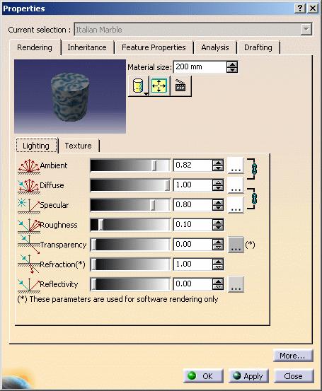
31 Modifying Material Lighting Properties Page 31 You can change the material size and mapping type as well as edit material specifications (lighting and texture parameters) of both linked and unlinked materials. Notes: Editing materials linked to libraries will modify the original material in the library. If you want to save changes made to the original material, use the File->Save All command Editing linked materials on parts in the same document or on parts in different documents will change all linked materials. This tasks explains how to edit the material lighting parameters. Open the Chess.CATProduct document. 1. Select the Italian Marble material in the specification tree. 2. Select the Edit->Properties command (or use the ALT+ENTER keyboard shortcut) to access material properties. Note: you can also right-click and select Properties from the contextual menu, or double-click the material. The Properties dialog box is displayed:
32 Page 32

33 Page 33 Note: the material properties can also be accessed by right-clicking the object onto which the material has been applied, then selecting the Material->Edit Material contextual commands. This avoids selecting the material in the specification tree and is especially useful when working in Full Screen mode, for instance. 3. Make sure the Rendering tab is active. Using this dialog box, you can edit the lighting and texture parameters of the material you are currently editing. Material specifications defined using Real Time Rendering are shared with other CATIA V5 products. For information on Drafting and Analysis tabs, see the Version 5 - Generative Drafting Version 5 and the Version 5 - Generative Part Stress Analysis user guides, respectively. Appropriate licenses are required to use these products. 4. Modify the Lighting parameters: ambient, diffuse, specular, roughness, transparency, reflectivity and refraction. You can either use the slider or enter the desired value directly in the field.
34 Page By default, the Ambient, Diffuse, Specular and Transparency colors are set to the basic color. You can, however, click [...] opposite Color and choose the color to be used for the material texture. The Transparency color is relevant for software rendering only (i.e. Photo Studio product). The Color dialog box is displayed allowing you to choose the exact color you wish to define as a material texture: You can click in the preview area to choose the color, or even key in the exact value of the desired color. You can enter a value comprised between 0 and 255 for any of these fields. As you can see it in the above picture, two color system models are used: HLS (Hue, Saturation, Luminance) model is an intuitive, easy to use tool for describing or modifying a color. Hue is the "color" of the color. It is the name by which the color is designated and is used to define the desired color. Saturation is the intensity of the color. The higher the number, the more intense the color. It is used to tune the purity of the color. Luminance is the brightness of the color, i.e. the degree to which the pure color is diluted by white or black. The larger the number, the lighter the color. It is used to adjust intensity
35 Page 35 RGB (Red, Green, Blue) model is a more physical model. It is based on the tristimulus theory of the human perception system. This model is usually used to define, with a high precision, the three primary components of the color. When satisfied, simply click OK, and the color is applied to the shape in the Properties preview. 6. Set the other material parameters: Parameter set to 0 (or 1 for Refraction) Parameter set to 1 (or 2 for Refraction) Ambient: the intensity of light diffused in any direction by the object, even if not lit by any light source. The ambient light is essentially used to show objects or parts of objects that are not illuminated directly by the light source. This parameter affects the whole object, including the shadowed area. The intensity is defined by a coefficient (with a value between 0 and 1). Diffuse: the intensity of light diffused by the object when lit by light sources. Typically, a shiny metal surface would have a diffuse reflectance value close to 0, while a piece of cardboard would have a value probably above 0.9. The intensity is defined by a coefficient (with a value between 0 and 1).
36 Specular: intensity and color of light reflected in one particular direction (highlights) Page 36 Set the value to a minimum to generate very sharp highlights on very shiny surfaces. Set the shininess to a higher value to generate large specular spots creating a duller effect. Typically, a polished object would have a high value for the specular reflectance coefficient, while a more mat surface would have a lower one. Roughness: dullness of an object (size of the reflecting zone) Set the value to a minimum to generate very sharp highlights on very shiny surfaces. Set the shininess to a higher value to generate large specular spots creating a duller effect on rougher surfaces. Transparency: degree of transparency of an object and color of the filter interfering with the light passing through an object. The transparency color acts like a photographic filter which modifies artificially the light rays received by an optical lens. It is generally identical to the ambient and diffuse color but when it is different, the shadows cast by the object are colored accordingly. For instance, a blue object with a red transparency color will cast slightly red shadows. The higher the value, the more transparent the object (in the example the value is 0.75), the lower the value, the more opaque the object.


37 Page 37 Refraction: degree of light passing obliquely through an object. The refraction is defined by a coefficient (value between 1 and 2). Set to 1, the transparent object will show no light distortion. As an example, water has a 1.2 coefficient. This parameter is relevant for software rendering only. Reflectivity: degree of reflectivity of an object. Set to a high value, the object reflects its environment. Set the Reflectivity parameter to 0.2 in order to see the reflections when a texture is applied. Otherwise, set this parameter to a value greater than 0 to see the texture. When setting the Reflectivity parameter, you can also set advanced reflection settings if you wish to use a customized environment image for environment reflections. For more information, refer to Defining Reflection Settings in this guide. A reflecting material lets you visualize the environment image it reflects. As you can use images of various origins for your environment, here is the priority order in which they are seen: 1. material reflectivity image defined in the Advanced Reflection Settings dialog box (for Real Time Rendering 2 users only) 2. environment image defined in the Tools->Options->Material tab 3. default environment image provided with Version 5. All values can be defined either using the scroll bar, the arrows or directly in the value field. If several values are to be modified, better skip from each value field to another using the tabulation key: in this case, the preview icon will be updated only once.
38 Page Click Apply to validate the material lighting definition. The material icon reflects the material as defined. Please note the following: All lighting parameter values range from 0 to 2 Any amount of reflectivity, however small, means that you will no longer visualize the mapped texture simultaneously with the reflected scene. If you want to see the texture, make sure you set the Reflectivity parameter to 0 in the Lighting tab.
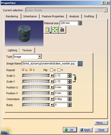
39 Modifying Material Texture Properties Page 39 This tasks explains how to edit the material texture parameters of both linked and unlinked materials. Open the Chess.CATProduct document. 1. Select the Italian Marble material in the specification tree 2. Select the Edit->Properties command (or use the ALT+ENTER keyboard shortcut). You can also right-click and select Properties from the contextual menu to open the Properties dialog box. Note: the material properties can also be accessed by right-clicking the object onto which the material has been applied, then selecting the Material->Edit Material contextual command. This avoids selecting the material in the specification tree and is especially useful when working in Full Screen mode, for instance. 3. Click the Texture tab in the Properties dialog box:
40 Page 40

41 Page In the Image Name field, navigate to locate the desired image, and click OK to map it onto the preview element as the texture. In the example, we choose the sky.tif image available with the default catalog. The following image formats can be used: tif: TIFF (Tagged Image File Format) rgb: Silicon Graphics 24-bit RGB color bmp: Microsoft Windows Bitmap Format jpg: JPEG (Joint Photographic Experts Group) pic: Apple Macintosh Format psd: Photoshop Format png: Portable Network Graphics tga: Truevision Targa file format The Type field indicates the type of texture you applied: Image: identifies materials with a texture. In that case, the corresponding image name is displayed in the Image Name field None: identifies materials with no texture such as metals. A preview area, in which different mapping types can be visualized, is also available:
. You can use it for textures with two privileged directions such as Chessboard or Wall of Bricks Spherical Mapping is similar to a painted light bulb.")
42 Page 42 These different mapping types are available to let you select the most appropriate mapping for the shape of the geometry: Planar Mapping is similar to a slide projector (a picture on a wall, for instance). You can use it for textures with two privileged directions such as Chessboard or Wall of Bricks Spherical Mapping is similar to a painted light bulb. You can use it for textures that do not have a privileged direction such as stone or raw metal Cylindrical Mapping is similar to placing a label on a can of food. You can use it for textures having a privileged direction such as shiny metal or marble Cubical Mapping is similar to wrapping a box Adaptive Mapping lets you choose between two mapping types: Automatic or Manual. The "Automatic" adaptive mapping automatically creates a planar mapping on each object face. "Manual" adaptive mapping gathers together faces which have close normal vectors. For each group of faces, a unique planar mapping is applied. The precision value defined using the slider modifies the tolerance used during the grouping process: the lower the precision, the more faces with greatly different normal vectors will be gathered together. This "Manual" mapping enables textures to cross slightly sharpen edges, thus providing higher visual quality. This mapping type is especially relevant for materials with no specific orientation such as leather or wood for example. Note: as "Manual" adaptive mapping is available for Real Time Rendering 2 users only, it will automatically change to "Automatic" adaptive mapping for Real Time Rendering 1 and Photo Studio users. Manipulations are available within the preview area: zooming in and out, rotating the support, translating it. Use the icon to reframe the support within the preview area.
43 Page 43 You can also manipulate the object (i.e. zooming in/out, etc.) directly in the geometry area while displaying the Properties dialog box either by double-clicking the material in the specification tree or by selecting Object->Definition... from the contextual menu. 5. If necessary, change the Material size to adjust the scale of the material relative to the part. 6. Define the image repetition along U and V, as well as its scale, its position and its orientation: U and V correspond to parameters of the local parametric surface. Repeat U, V: lets you specify whether or not you want the texture repeated ad infinitum along u- and v-axes Scale U, V: determines how the texture is stretched along u- and v-axes Position U, V: determines the position of the texture along u- and v-axes. By default, the image is centered Orientation: defines the rotation of the texture on surfaces. 7. Use the Flip U, V checkboxes to invert the material texture along U and V axes. You can click the Link U and V scales icon to resize U and V proportionally. This is especially useful for square shapes, the Floor material for instance. Note that when this option is on, the Scale V field is grayed and the icon changes to. The Inheritance tab displays information about the material inheritance mode and the checkboxes are grayed until a material is applied. 8. Click the Analysis tab if you wish to edit the material physical properties, such as the density and so on. These data will be used for calculation purposes in the Version 5 - Generative Structural Analysis User's Guide.


44 Page 44 Note: appropriate licenses are required to use this tab. 9. Click the Drafting tab if you wish to set the pattern used for creating section views or section cuts:
45 Page 45 When a material is applied onto a product, the pattern information will be used only for the part(s) contained in the product. For more information, refer to the Version 5 - Generative Drafting User's Guide. Note: appropriate licenses are required to use this tab. 10. Click OK (or Apply then OK) to validate the material texture definition. The material icon reflects the material as defined. There is no specific order when defining parameters. 11. Position the material interactively using the 3D compass as explained in Applying a Material.
46 Copying Material Rendering Parameters Page 46 This tasks explains how to copy the rendering parameters from one material to another. Open the GettingStarted.CATProduct document. The document looks like this: 1. Select the material in the specification tree. 2. Right-click then select the Copy Rendering Data contextual command to open the Copy Parameters dialog box.

47 Page 47 Note: the Copy Parameters dialog box can also be accessed by right-clicking the object onto which the material has been applied, then selecting the Material->Copy Rendering Data... contextual command: This avoids selecting the material in the specification tree and is especially useful when working in Full Screen mode, for instance.
 have been replaced on the selected material. In our example, we chose the \"Walnut\" material from the \"Wood\" family:")
48 Page Select a material from the list. By default, all materials are displayed. However, you can use the pulldown list to sort the materials by family before selecting the desired material. 4. Click OK to validate. The rendering parameters (i.e. lighting and texture parameters) have been replaced on the selected material. In our example, we chose the "Walnut" material from the "Wood" family:

49 Page 49 The material name remains the same as well as the other material parameters such as Analysis, Drafting and so on.

50 Page 50 Replacing a Material Link This tasks explains how to replace the link to a material with a link to another material. This functionality is relevant for linked materials only Only the documents open in your current session will be impacted There is no impact on the material catalog which will not be modified. Therefore you can work with a read-only catalog. Open the Materials.CATProduct document. The same material ("Gold") has been applied onto each part: You can also see that two of the three materials have been applied with a link to the material catalog: these materials are identified by a white arrow in the specification tree:.
 in the specification tree then select the Replace Material Link... contextual command to open the Replace Link dialog box.")
51 Page Select one of the materials in the specification tree. 2. Right-click it then select the Properties contextual command to display the material properties: 3. Click Close. 4. Right-click the first "Gold" material (which is a linked material) in the specification tree then select the Replace Material Link... contextual command to open the Replace Link dialog box.

52 Page 52 Note: the Replace Link dialog box can also be accessed by right-clicking the object onto which the material has been applied, then selecting the Material->Replace Material Link... contextual command: This avoids selecting the material in the specification tree and is especially useful when working in Full Screen mode, for instance.

53 Page 53 The Replace Link dialog box always opens the default material catalog, whether it is the one provided by Dassault Systèmes or a user-defined catalog. 5. Select a material from the list. By default, all materials are displayed. However, you can use the pulldown list to sort the materials by family before selecting the desired material. In our example, we will choose "Floor" in the "Construction" family. 6. Click OK to validate.

54 Page A message displays to ask you whether the replacement should be propagated to all the materials in your session: click Yes to replace all the occurrences of the selected material in all the products open in your session click No if you want to replace the selected material on the current product only. In our example, we will click Yes. The two "Gold" materials applied with a link are replaced with the "Floor" material and the product now looks like this: Moreover, when looking at the specification tree you will see that only the linked materials have been replaced, the "Gold" material applied without link is still applied onto one of the parts. 8. Now, access the material symbol in the specification tree. You can see that it has changed from to. The new material has also been applied with a link to the material catalog,.
55 Page Right-click the Floor material in the specification tree then select the Properties command: The properties now displayed are those of the "Floor" material and not those of the "Gold" material anymore.

56 Finding Materials Page 56 This task explains how to use the search for materials in documents. This is useful in large assemblies where you will be able to rapidly identify materials of interest. You can then, if desired, individually edit selected materials. For more information on the Search command, see the Using the Search... command (General Mode) task in the Version 5 Infrastructure User's Guide. You can also perform advanced queries and save your favorite queries using the Advanced and Favorites tab. For more information, refer to the Using the Search... command (Advanced and Favorites Mode) task in the Version 5 Infrastructure User`s Guide. Open the SaltnPepper.CATProduct document. 1. Select the Edit -> Search... command to open the Search dialog box. 2. Click the General tab.

57 Page Set the Workbench field to "Rendering". 4. Set the.type field to "Material". 5. Ensure the Look box is set to "Everywhere" to search the whole product structure. 6. Click Search to start the search The search results are listed in the area in the lower half of the Search dialog box.

58 Page Click Select to select found items and then OK to exit the dialog box. 8. Expand all entries in the specification tree to see that all mapped materials have been selected:

59 Page Select the Edit->Properties command: The Properties dialog box appears letting you edit the properties of selected materials. Click the Current selection drop-down list box and select the materials in turn to edit them. For more information on editing materials, see Modifying Material Lighting and Texture Properties. To edit other materials in your document, de-select the first material in the specification tree then select the Edit -> Properties command again.

60 Page 60 Copying & Pasting Materials Using Paste Special... When you use the Paste Special... command, material is pasted as a linked object. You can copy a: Material from a library: The part will be automatically updated to reflect any changes to the original material in the library. This is also useful in large assemblies if you have material specifications that may change and that you use in more than one place. Materials can also be mapped as linked objects from libraries using the Link to file checkbox in the Library dialog box. Paste the material on a different part in the same document: The link is made from the second part to the first part. Editing the material on either part will automatically update the material on the other part Paste the material on parts in different documents: Editing the material on any part will automatically update all linked materials on all parts in all documents. You can in this way change the material specifications in all places where they appear without having to edit each individual occurrence. This tasks explains how to copy and paste materials using the Paste Special... command. Open the EditMaterial1.CATMaterial and Paste.CATProduct documents. 1. Select the material you want to copy from the EditMaterial library. 2. Copy the material. To do so, you can either: Click the Copy icon Select the Edit->Copy command or Select the Copy command in the contextual menu 3. Select the part onto which you want to map the material (Part2 in our example) 4. To paste, you can either: Select the Edit->Paste Special... command or Select the Paste Special... command in the contextual menu The Paste Special dialog box appears:

61 Page Click Material Link in the dialog box, then click OK. The material is mapped onto the selected part and the specification tree updated. A linked material icon identifies the material in the specification tree. Note: You cannot change the material name in the Feature Properties tab of the Properties dialog box. For detailed information about the Paste Special... command, refer to Using the Paste Special... command. Simple copy and paste as well as drag and drop operations can also be performed. In both cases, the mapped material is not linked. Managing Broken Links Mapping a material as a linked object sometimes leads to a broken link when the mapped material is not found. This task details in which cases this may occur. Open the EditMaterial1.CATMaterial and Pad.CATProduct documents and select the Shading with Material icon from the View toolbar. 1. Select the Edit->Links command from the main menu to open the Links... dialog box: 2. Close the Links dialog box then move the document EditMaterial1.CATMaterial to another folder. 3. Restart your session, then reopen the document Pad.CATProduct. The Open dialog box appears, explaining that the document EditMaterial1.CATMaterial could not be found:


62 Page 62 A different icon material. identifies the broken link in the specification tree and will appear in any document referencing this There are several reasons why a link with a material may no longer work: the material has been deleted. In that case, the link cannot be restored since the material has been definitely lost the material has been moved or renamed which means that it exists but it is different from the file pointed to. In that case, the pointed document will be searched in: the current session the directory of the loaded document the default material library. This library is defined in the CATStartupPath variable or in the Material Libray subcategory (under the Tools->Options...->Infrastructure->Material Library category). If the material is found then the broken link icon is replaced with the linked material icon in the specification tree. Otherwise, the broken link icon is still displayed in the specification tree and you can try to restore the link manually using the following method: 4. Click the Close button then select the Edit->Links... command:
63 Page Click the Pointed documents tab. This activates the Find button and provides you with the path and name of the document pointed to in the session. 6. Click the Find button to open the File Selection dialog box, explore your file system to find the corresponding missing file, select it, then click Open. The File Selection dialog box can be directly accessed from the Open dialog box (introduced in Step 3) either by double-clicking the file path inside the field or by clicking the Desk button. In both cases, the Desk opens and you just have to select the CATMaterial before choosing the Find... contextual which opens the File Selection dialog box. 7. In the Links... dialog box, click the Open button. The dialog box disappears and the EditMaterial1.CATMaterial is displayed. 8. If you now select the Edit->Links... command with the EditMaterial1.CATMaterial document active, the Links... dialog box will indicate that the right material library has been found and loaded. For more information on managing document links, refer to the Version 5 Infrastructure User`s Guide. Use the Send To->Mail/Directory command from the File menu when you want to send a document to another person. This command enables you to check the various links existing between your documents and thus, to avoid broken links.
64 Using Knowledge Advisor Capabilities Page 64 Material specifications defined using Real Time Rendering are shared with Knowledge Advisor. This is illustrated in the two tasks below. In our examples, you will change the material mapped onto a part or a product directly in the knowledgeware Formulas dialog box as well as write a rule using material as a parameter to, for example, change the mapped material as a function of hole diameter. For more information on Knowledge Advisor, see the Version 5 - Knowledge Advisor User's Guide. Note that to use this product you need the appropriate license. Changing the Material Mapped onto a Part or a Product Directly in the Formulas Dialog Box This tasks explains how to change the material mapped onto a part or a product directly in the knowledgeware Formulas dialog box. Open the ChangeMaterial.CATProduct document. 1. Click the Formula icon in the Standard toolbar. The Formulas dialog box appears listing all the part parameters. 2. Select the Material parameter. The Edit name, value or formula fields are updated.

65 Page Enter another material, Gold for example, directly in the value field The dialog box, part itself and specification tree are all updated. You have changed the material mapped onto the part directly in the dialog box. You can only change materials mapped in the Formulas dialog box to those available in the default material library. Any material changed in this way will be mapped as linked objects and will be automatically updated to reflect any changes to the original material in the library. Note: The material icon in the specification tree appears with a link to indicate that the material gold is mapped as a linked object.

66 Page 66 Writing a Rule This task explains how to write a rule using material as a parameter to, for example, change the mapped material as a function of hole diameter. Open the WriteARule.CATProduct document. Make sure that the Shading with Material icon has been selected from the View toolbar. 1. Select Tools -> Options.... In the Mechanical Design category, select the Part Design subcategory then click the Relations checkbox in the Display tab to display relations in the specification tree 2. Select the part 3. Select Knowledge Advisor from the Start -> Knowledgeware menu 4. Click the Rule icon: The Rule Editor dialog box appears. 5. Click OK to identify your rule in the Rule Editor dialog box. The Rule Editor : Rule 1 dialog box is displayed. You can now write your rule. 6. Write the following rule: if (PartBody\Hole.1\Diameter > 60mm) Material = "Gold" else Material = "Aluminium"

67 Page 67 For detailed information on the Knowledge Advisor rules, refer to "Using Rules" in the Version 5 - Knowledge Advisor User's Guide. 7. Click OK when done: The system checks that your syntax is valid. If it is not, you are prompted to correct it. You cannot edit or apply materials that have been incorporated as parameters into rules. You can now check your rule. 8. Select Part Design from the Start -> Mechanical Design menu 9. Right-click the hole and select Hole1.Object -> Edit Parameters from the contextual menu 10. Double-click the hole diameter and enter a new value in the Constraint Edition dialog box, for example 70, then press Enter The material changes from aluminium to gold.


68 Page 68 Before: After: Note: Materials incorporated as parameters into rules are mapped as linked objects. Linked materials are identified in the specification tree by a material icon with a white arrow symbolizing the link.

69 Defining Reflection Settings Page 69 This tasks explains how to define advanced reflection settings for a material in case you do not intend to use the default environment reflections. Open the ApplyMaterial.CATProduct document. 1. Access the Aluminium material properties. The Properties dialog box is displayed:

70 Page Click the... button beside the Reflectivity field to open the Advanced Reflection Settings dialog box: This displays the default environment provided which can be seen on the teapot you opened a few steps before. However, as this image will be used for reflection purposes only, you will not be able to visualize the environment reflections on the object unless you set the Reflectivity parameter to the a non-zero value (provided that the object itself is reflecting).

71 Page Use the Environment Image field to define another texture image. You can either enter a file name directly in the field or click the... button to navigate to the desired file. Note: the button lets you reset the environment image to the default image. 4. If you wish to create your own environment image, click the icon to open the Environment Image Generator dialog box:

72 Page In the upper part of the dialog box, just click each environment wall (i.e. "Up", "Back", etc.) then navigate to the desired image using the File Selection dialog box. The resulting environment will be displayed on the environment map as shown below: 6. The Image Size pulldown list lets you choose a Small, Medium or Large size for your environment image. 7. Enter the name and path of the generated image in the "Save as" field or click the icon to open the File Selection dialog box which lets you browse your folders to the desired location. 8. Click OK to validate and go back to the Advanced Reflection Settings dialog box.


73 Page Choose the environment Reflection Type: Chroma, Paint, Matte Metal, Bright Plastic or Custom. Chroma Paint Matte Metal Bright Plastic Selecting "Custom" activates the Transparency Width and Transparency Height fields to let you specify the desired ratios (values comprised between 0 and 1) for the transparency filter. 10. Click OK. The environment image is defined. This image supersedes the environment image you may have chosen in the Environment Image File field in the Material General Settings tab.

 is reflected on the")
74 Page 74 Activating/Deactivating Material Reflections In this scenario, you will learn how to the reflections displayed on your materials, whether they are emitted from the default environment or from a customized environment image. Open the ApplyMaterial.CATProduct document. As you can see it in the picture below, an environment image (the default one, in our example) is reflected on the teapot: 1. Select Tools->Customize... then click the Commands tab:
75 Page Under Categories, select "All Commands" then in the Commands list to the right, select Activate/Deactivate Reflections. 3. Drag the command from the command list to the toolbar to which you want to add the command. 4. Drop the command onto the desired toolbar. In our scenario, the icon for the Activate/Deactivate Reflections command has been added to the Scene Editor toolbar: 5. Click the Activate/Deactivate Reflections icon. The reflections are no longer displayed and you can compare the two different results below: Activation Deactivation 6. To re-activate the material reflections, click the Activate/Deactivate Reflections icon again. The Activate/Deactivate Reflections icon lets you switch from one display mode to another.
76 Cameras Page 76 Creating a Camera Using Knowledgeware Parameters

77 Creating a Camera Page 77 The camera enables you to specify a viewpoint from which a photorealistic image will be computed. This task will show you how to create a camera and manage its specifications. Open the Lamp.CATProduct document. 1. Click the Create Camera icon. The camera is created at the current viewpoint. 2. Click the Camera item in the specification tree and rotate the model to see the camera symbol:

78 Page 78 This standard visualization is not affected by any change of scale ("zoom"). In case you wish to hide the camera representation, click the camera in the specification tree then select the Camera object->hide/show Representation contextual command. Inversely, this command lets you show a hidden representation. You can create several cameras at different locations to have different viewpoints. The camera which is taken into account to render a given image is said to be active. Any other camera is inactive. 3. Use the two spheres and the two squares displayed in green on the 3D representation to interactively manipulate and position the camera. This visualization is affected by changes of view scale (zoom) and is activated when selecting a camera in the scene or in the specification tree. Otherwise, all elements are set to the standard visualization. Conical camera Pyramid height = focal length and Pyramid base = film dimensions Cylindrical camera Plane = film dimensions the source point (1) rotates the camera around its target point the target point (2) rotates the camera around its source point the source green square translates and rotates the camera around its target point the target green square translates and rotates the camera around its source point. Cameras are needed to render and view a scene. "An image is worth a thousand words": the better the camera is positioned, the more accurate the saying is.

79 Page Select the camera in the specification tree then right-click and select the Properties command. The Properties dialog box is displayed:
80 Page In the Lens tab, select the lens Type: Perspective or Parallel, i.e. to obtain a conical or a cylindrical projection. The Preview area shows the result of your selection accordingly. A conical camera is equivalent to a standard camera, with a non-zero focal length. Parallel lines in the camera line of view appear to intersect at the same point. Perspective cameras are used in most cases since they are close to the human vision. In the case of a cylindrical camera, parallel lines never appear as intersecting. These cameras are mainly used to define architectural viewpoints. 6. Specify the Focal Length, which determines the field of view, in millimeters. In a cylindrical projection, the focal length is replaced by a zoom factor which determines the scale of view (i.e. "Scale" appears instead of "Focal Length" in the dialog box).

81 Page 81 You can also specify the camera view directly inside the preview window by zooming, rotating or panning the view.


82 Page Click the Position tab to define the target and origin position. You can define the Origin and the Target position in millimeters along the X, Y and Z axes. If you are not satisfied with the values you defined, you can click the desired parameter to reset its value. button next to the The Feature Properties tab provides general information on the currently selected camera, e.g. its name, its creation date, etc. Snapping the compass to the camera lets you modify the camera position and orientation very easily simply by dragging the arcs of the compass as shown below:
83 Page 83 For detailed information about compass manipulation, refer to Moving Objects Using the 3D Compass in the Infrastructure User`s Guide. 8. Check the Update camera from View option if you wish to update automatically the camera when the viewpoint is modified: Picture 1 - Camera with Original Viewpoint Picture 2 - Camera after viewpoint modification This avoids selecting the Update From View contextual command each time a viewpoint modification is done. 9. Click OK when finished. 10. In case you want to position yourself behind the camera and observe the captured image, select the Window -> Camera Window command: a new window displaying the camera viewpoint is opened. When you manipulate the handler in this window, the camera is simultaneously positioned in the main window. Note: You can choose three arrangements for the opened windows, i.e. horizontal, vertical and cascading by selecting the following commands from the menu bar: Window -> Tile Horizontally Window -> Tile Vertically Window -> Cascade

84 Page 84 Example of vertical tiling You can double-click the Camera item in the specification tree to position the camera from the current point of view. You can also select the camera in the specification tree then the Update From View contextual menu to update the camera when the viewpoint is modified.
85 Using Knowledgeware Parameters Page 85 The camera shows you how to control camera parameters using Knowledgeware tools. This enables you to link parameters to constraints like formulas in order to, for instance, automatically update the camera position whenever the object is moved. Open the Lamp.CATProduct document. 1. Create a camera by clicking the Create Camera icon. The camera is created at the current viewpoint. You can refer to Creating a Camera for detailed information on cameras. 2. Make sure that the camera is selected either in the geometry area or in the specification tree then click the Formula icon from the Knowledge toolbar to open the f(x) dialog box:

86 Page 86 The Parameter list displays the parameters related to the camera: KweType: controls the lens type of the camera. This parameter is an integer and you can choose between "0" for perspective or "1" for parallel. The default value is "0" KweViewAngle: controls the view angle of the camera. The default value is "15 " KweFocus: controls the focal length (i.e. the field of view) for perspective cameras. The default value is "420mm" KweZoom: controls the zoom factor (i.e. the field of view) for parallel cameras. The default value is "1" KweVisuMode: controls the representation of the camera, i.e. whether the camera is displayed in the geometry area or not. The default value is "1" which means that the camera is displayed KweUpdateFromView: controls the update mode of the camera. You can choose between "0" to indicate that the camera should not be updated when the viewpoint is modified and "1" to indicate that the camera should be updated. The default value is "0" KweOriginX: controls the position of the camera origin along the X axis (in mm) KweOriginY: controls the position of the camera origin along the Y axis (in mm) KweOriginZ: controls the position of the camera origin along the Z axis (in mm) KweTargetX: controls the position of the camera target along the X axis (in mm) KweTargetY: controls the position of the camera target along the Y axis (in mm) KweTargetZ: controls the position of the camera target along the Z axis (in mm) KweZenithX: controls the rotation of the camera around the X axis KweZenithY: controls the rotation of the camera around the Y axis KweZenithZ: controls the rotation of the camera around the Z axis.
87 Page To edit a parameter, select it from the list: the selected parameter appears in the "Edit name of the value of the current parameter" field along with the corresponding value in the field to the right. In this scenario, we will select the KweUpdateFromView parameter: 4. Enter the "1" in the field displayed to the right to indicate that the camera should be updated according to the viewpoint. For detailed information on how to use the other fields available from this dialog box, refer to Getting Familiar With the f(x) Dialog Box. 5. Click OK or Apply + OK to validate and close the dialog box. The parameter is modified. 6. Modify the viewpoint (by rotating the object, for instance) and check the result: the camera is updated accordingly as shown below: Picture 1 - Camera with original viewpoint Picture 2 - Camera after viewpoint modification You can also create formulas to constrain the parameters of your choice. For instance, you could associate the center of a part to the camera target so that the camera position changes according to the the object position. For detailed information on how to create and use formulas, refer to Formulas.
88 Viewing Objects Page 88 Editing the View Angle
89 Editing the View Angle Page 89 This task explains edit interactively the view angle. The view angle sets the angle of the pyramidlike shape with which you look at the geometry (available in perspective views only): Open the Chess.CATProduct document. 1. Select the View->Commands List... command then choose "View Angle" from the list or enter directly c:view angle in the power input field. The View Render Style dialog box prompts you to choose the desired view mode: either "Perspective" or "Parallel".

90 Page Select "Perspective". A green circle appears with an arrow indicating the current view angle as shown below: Note that the current view angle is identical to the view angle you define in the Camera properties when working with user-defined views. 3. Drag the green arrow (which turns red) to change the view angle. Bear in mind that the angle cannot exceed 90.
91 Page 91 At this step, you can click Cancel to close the View Render Style dialog box and go back to the current view angle. 4. When you are happy with the result, click OK to close the View Render Style dialog box and apply the new view angle.
92 Light Sources Page 92 Defining a Light Source Adjusting Light Source Parameters Creating Real Time Shadows Creating Object-to-Object Shadows Using the Light Commands Toolbar

93 Defining a Light Source Page 93 This task shows you how to create a light source. Lights let you illuminate the objects to be rendered as you wish for example, by highlighting a specific element in your scene, thus focusing the viewer's attention. Open the Lamp.CATProduct document. You can choose between three different types of light sources: spot, point and directional. 1. Click the Create Spot Light icon to create a light source with a conical shape: Note that the representation of the light source displayed above corresponds to the default representation mode (i.e. "wireframe display). You can choose to display the light source in shading mode by checking the corresponding option in the Tools->Options- >Infrastructure->Rendering->Display tab.
 and the angle that the edge of the cone forms with this axis.")
94 Page 94 This light source is located at a given place, emitting the light isotropically inside a cone of influence determined by the privileged direction of illumination (forming the axis of revolution) and the angle that the edge of the cone forms with this axis. Spot light sources are mainly used to simulate spot light (the most frequently used lights) and are useful for tuning the lighting of each object individually. You can also click the Create Point Light icon to create a light source situated at a given point, emitting light isotropically, i.e. in all directions. This light source type is mainly used to simulate light bulb, for instance. or click the Create Directional Light icon...

95 Page to create a light source coming from a given direction, generating constant intensity parallel lighting. This light source type is mainly used to simulate a global lighting as the sun does. Note: you can click anywhere in the geometry area to see the light symbol: Spot light Punctual light Directional light Direction vector represents the privileged direction of illumination of the source for spot and directional light sources. It is visualized by an arrow whose origin is the anchoring point of the source. Anchoring point is the position of the light source and is represented by a small star. When the source is characterized by a direction, the anchoring point coincides with the origin of the arrow. In the case of a spot or punctual light source, the anchoring point physically localizes the source. In the case of a directional light source, it can be used (with the target point) to define the illumination direction. 2. As for cameras, you can interactively manipulate a light source:
96 Page 96 the source point (1) rotates the spot around its target point the target point (2) rotates the spot around its source point the upper green manipulator translates and rotates the spot around its target point the lower green manipulator translates and rotates the spot around its source point. It also lets you modify the attenuation end. 3. To activate a light source, simply select it in the specification tree then check the Light On option from the contextual menu. Inversely, to deactivate a light source, simply select it in the specification tree then uncheck the Light On option from the contextual menu. Light sources illuminating the scene are said to be active (On). Otherwise, they are inactive (Off) and do not cast any light.
97 Page 97 Due to OpenGL limitations, some active lights may not be seen in the 3D window though they are defined as being "active". In that case, a warning sign identifies the light in the specification tree. On most platforms, up to 8 lights can be seen at the same time, however this number may be higher depending on the graphics card. You are now ready to adjust the light source parameters. Automation Macros are provided to automate the activation/deactivation of light sources. Refer to the "Use Cases" section in the Real Time Rendering Automation documentation for detailed information.

98 Adjusting Light Source Parameters Page 98 This task aims at showing how to adjust an existing light source so that it best suits your needs. Open the Lamp.CATProduct document. This scenario assumes that a light source has been created as explained in Defining a Light Source. 1. Select the light then the Edit->Properties command (or use the ALT+ENTER keyboard shortcut) to access the Lighting tab in order to edit the lighting parameters. You can also select the light in the specification tree then the Properties or the Light object- >Definition... command from the contextual menu also opens the Properties dialog box: The Type field lets you modify the source type by selecting a new type from the pulldown list: Spot, Point or Directional.
99 Page Use the slider to modify the color intensity, then click the button if you want to choose another color (the default color is white): You can enter a value comprised between 0 and 255 for any of these fields. The overall color of a light source is composed of three independent colors: diffuse, ambient an specular. The values of these colors are given in RGB mode or in HLS mode by three real positive values: HLS (Hue, Saturation, Luminance) model is an intuitive, easy to use tool for describing or modifying a color. Hue is the "color" of the color. It is the name by which the color is designated and is used to define the desired color. Saturation is the intensity of the color. The higher the number, the more intense the color. It is used to tune the purity of the color. Luminance is the brightness of the color, i.e. the degree to which the pure color is diluted by white or black. The larger the number, the lighter the color. It is used to adjust intensity RGB (Red, Green, Blue) model is a more physical model. It is based on the tristimulus theory of the human perception system. This model is usually used to define, with a high precision, the three primary components of the color.
100 Page Click OK to confirm and close the Color dialog box. 4. Define the light Intensity using the slider or the value-entry field. The intensity of a light source is the maximal lightness value of three colors (ambient, diffuse and specular). The light color will be computed by multiplying the Red, Green and Blue values you defined in previous step by the intensity value. Therefore, this parameter allows you to adjust the luminosity of the light source, while preserving its chrominance ("color") component. You can enter values comprised between 0 and 4: the higher the value, the more saturated (i.e. the whiter) the light. More precisely, as soon as the intensity value exceeds 1, the color starts saturating. Here are two examples comparing 2 different sets of RGB values with 3 different intensities. In the first example, all color components (R, G and B) are multiplied by intensity: R,G,B = 10,100,10 R,G,B = 10,100,10 R,G,B = 10,100,10 Intensity = 0.5 Intensity = 1 Intensity = 3 Result = 5,50,5 Result = 10,100,10 Result = 20,255,30 In the second example, when the intensity is greater than 1, R and B are the only components to be multiplied since G is already saturated:


101 Page 101 R,G,B = 40,255,40 R,G,B = 40,255,40 R,G,B = 40,255,40 Intensity = 0.5 Intensity = 1 Intensity = 3 Result = 20,128,20 Result = 40,255,40 Result = 120,255, To define more precisely the light intensity, click the button which opens the Intensity dialog box:

102 Page 102 This dialog box lets you define three coefficents using the slider or by entering a value directly in the corresponding field: Ambient: defines the intensity of light emitted in any direction by the object, even if not lit by any light source Diffuse: defines the intensity of light diffused by the object when lit by a light source Specular: defines the intensity and color of light reflected in one particular direction. This coefficient affects the highlight on shiny surfaces. Ambient, Diffuse and Specular coefficients only impact the material aspect. They are identical to those used to define material lighting properties (and are used in combination with them) but have no influence on the material definition. Example of use: when visualizing a model on screens with different characteristics (e.g. LRT screen versus LCD screen), you can recalibrate the screen simply by modifying the light intensity using these three coefficients. You do not need to modify all the materials. The following images show how Ambient, Diffuse and Specular coefficients impact the material aspect: "Ambient" only: "Diffuse" only: "Specular" only: - no relief - relief - no relief - no highlight - no highlight - highlight
 and stops at attenuation end.")
103 Page The Falloff field lets you define the light energy attenuation (which is set to None by default): None: no lighting end which means that the light energy will be constant and infinite. The cone limits, however, are kept Linear: light energy decreases linearly with a 1/r ratio ("r" = distance to light origin) and stops at attenuation end. For instance, if the energy received at a distance of 10 mm from the light origin will be equal to 1/10th of the light energy at light origin Realistic: light energy decreases with a 1/r 2 ratio and becomes negligible at attenuation end. A realistic falloff requires a high value when distant objects are to be illuminated. Note: directional lights do not disperse and therefore have no falloff. The following picture illustrates the three different types of light energy attenuation:
.")
104 Page The Lighting tab also lets you define: Source Angle Enables you to define the half-angle of the cone, that is the angle between the axis of revolution and the cone edge (for spot light sources only). The angle is a value between 0 and 90 degrees. This means that a value of 90 degrees would generate a light source equivalent to a punctual light source. Attenuation End Defines in millimeters the maximum distance for light attenuation (i.e. the distance to the center from which the light source does not illuminate). Attenuation Start Ratio Defines as a ratio the minimum distance for light attenuation. For example: 0 corresponds to an attenuation starting from the center 0.5 corresponds to an attenuation starting from the middle 1 corresponds to an attenuation starting from the end, i.e. a null attenuation.


105 Page 105 Attenuation Angle Ratio Defines as a fraction of the light angle the angle to the light axis from which the light starts to attenuate. For example: 0 corresponds to an attenuation starting from the axis 0.5 corresponds to an attenuation starting from the half-angle 1 corresponds to an attenuation starting from the end, i.e. a null attenuation. Note that you also position your pointer over the one of the side lines then click and drag the segment to modify the attenuation angle ratio. The Ray Traced option available in the Shadows tab is relevant for software rendering only (i.e. Photo Studio products). 8. Click the Position tab to define the light source anchoring point and the point to which the source is directed, respectively in the Origin and Target areas. You can define this position in millimeters along the X, Y and Z axes.
106 Page 106 Note that you can click the button at anytime to reset the light source to the default position. 9. The Reference Axis area lets you define the light source position relative to the Model axis or to the Viewpoint according to the radio button you select: Model By default, any light source you create is positioned relative to the model and thus, moving the viewpoint moves the light source along the model. Click the thumbnail below to see the corresponding animation: Viewpoint Attaching a light source to the viewpoint means that moving the viewpoint only moves the model; the light source keeps the same position in the window. Click the thumbnail below to see the corresponding animation: When a light source is attached to the viewpoint, it is identified by an anchor symbol in the specification tree as shown below for Light 1: Note that you can also attach a light source to the viewpoint by right-clicking it in the specification then selecting Attach to View. Inversely, once a light source is attached to the viewpoint, you can re-attach it to the model by unchecking Attach to View.
107 Page 107 The Feature Properties tab provides general information on the currently selected light source, e.g. its name, its creation date, etc. 10. If you want to display the light source viewpoint (to visualize the object as if you were positioned behind the light source), right-click the light item in the specification tree then select the Light View contextual command: To go back to the original view, select the View->Modify->Previous View commands or click the Previous view icon from the Viewpoint toolbar. Then, you can switch again to the light view by clicking the Next View icon. Right-clicking the light item in the specification tree also lets you select the Update From View contextual command to adjust (i.e. center) the light source when the viewpoint is modified as shown below: Update From View -->
108 Page If you want to position the light source along a perpendicular to the point you click on the object. To do so: right-click the light source item in the specification tree (or the light symbol in the geometry area) and select the Position Along Normal contextual command then place your pointer over any point of the object and click: the light source is positioned along the normal to the selected point. Note that as long as the Position Along Normal command is active, you can hold down the left-mouse button and keep on moving the cursor to find the best position: when satisfied, release the mouse button to position the light source. Click the thumbnail below to see the corresponding animation: When satisfied with the result, deactivate the Position Along Normal command by selecting any other command in the workbench or by pressing the Esc key. 12. You can also adjust the specular effect of your light source. To do so: right-click the light source item in the specification tree (or the light symbol in the geometry area) and select the Position Specular contextual command then place your pointer over any point of the object and click: the specular spot is positioned at the selected point.
109 Page 109 Note that as long as the Position Specular command is active, you can hold down the leftmouse button and keep on moving the cursor to find the best position for the specular spot: when satisfied, release the mouse button to position the specular effect. Click the thumbnail below to see the corresponding animation: When satisfied with the result, deactivate the Position Specular command by selecting any other command in the workbench or by pressing the Esc key. 13. Click OK to apply the parameters to the light source.

110 Creating Real Time Shadows Page 110 In this task, you will learn how to create real time ground shadows to simulate in a very realistic way the reflections of an object on its environment walls. Open the Lamp.CATProduct document. 1. Create a directional light source by selecting the Create Directional Light icon Only directional light sources can cast real time ground shadows. 2. Create an environment (you can also apply textures on the walls). The model should look something like this: Note: in case no environment exists, a default environment (very big and with transparent walls) will be created.

111 Page In the specification tree, select the Bottom wall and display its lighting properties by selecting the Properties... contextual command then the Lighting tab to make sure that the Shadows option is "On". 4. Access the lighting Properties dialog box (by selecting the light in the specification tree then the Properties or the Light object->definition... contextual command), select the Shadows tab then activate the On Environment option: 5. Set the following parameters using the corresponding slider or enter directly a value in the corresponding field: Smoothing: defines the shadow attenuation, i.e. the limit between light and shadow. The higher the value, the more attenuated the limit. For instance, "0" means a clear break with no attenuation at all Color: lets you define the color of the shadow by clicking the button to select the desired color. The slider sets the color intensity Transparency: sets the opacity of the shadow. The higher the value, the less opaque the shadow.

112 Page Click OK to validate when satisfied with your parameters. The shadow of the lamp now appears on the bottom wall as shown below: You can move the created shadow simply by dragging and dropping the compass onto it. Automation Macros are provided to automate the activation/deactivation real time shadows. Refer to the "Use Cases" section in the Real Time Rendering Automation documentation for detailed information.

113 Creating Object-to-Object Shadows Page 113 This task shows you how to enable shadow-casting between objects. Open the FindMaterials1.CATProduct document. 1. Create a spot light source by selecting the Create Spot Light icon Only spot light sources can cast shadows between objects. Note also that object shadows are supported on NT only and that we recommend the following graphic boards: nvidia Quadro4 750XGL, NVidia Quadro4 900XGL, ATI Radeon 8800, FireGL2 or Wildcat Access the Lighting properties dialog box by right-clicking the light in the specification tree then selecting Properties. 3. Click the Shadows tab and check the On objects option to activate shadow casting between objects: Only one light source can cast shadows at a time. As a consequence, when the On objects option is activated, other light sources you may have previously created (as well as the standard light sources defined using the View->Lighting... command) are deactivated and identified by a specific symbol in the specification tree. In the following example, Light 3 cast shadows on objects and Light 1 and 2 are deactivated:

114 Page 114 Moreover, note that creating a new light source automatically switches shadows off for the other light sources. To switch shadows from one light source to another, access the light source properties then check the On objects option: a warning window will appear to prompt you to confirm your choice. When the On objects option is activated, the light source angle cannot exceed 45. Inversely, defining a light source with an angle greater than 45 prevents you from creating shadows between objects. 4. Use the Map Precision pulldown list to define the size of the shadow map: Small Medium Large. A shadow map is a kind of map identifying illuminated points in the scene with respect to a given light source. This ray-tracing technique relies on a precomputed depth map attached to the light source. The higher the map precision, the more accurate the shadows but bear in mind that there is a price to pay in performance and allocated memory. 5. Define the shadow Quality which enables you to optimize the performance by selecting a value from the list: Standard: this is the default value. In that case, the shadow map is not recomputed at each interaction Good: the shadow map is recomputed at each interaction, which provides a more accurate shadow but affects performance. We recommend that you start with a low precision with a standard quality then, when satisfied with your lighting parameters, increase Map Precision and Quality. 6. Select the Near Plane mode: either Automatic or Manual. The field is activated as soon as you move the light in the geometry area. The Near Plane corresponds to the minimum distance from the light origin and is represented by a dotted rectangle in the light source symbol:

115 Page 115 The near plane distance is used when you want to focus on a specific part of the scene as if viewed from behind the light source. Each part of the scene positioned between the near and far distance will be taken into account to compute the shadow. Near and far plane distances have an impact on the shadow map quality: the greater the distance, the less accurate the details of the object. Automatic: this is the default mode which means that the near plane is automatically adjusted according to the current viewpoint and the bounding box. This bounding box is not the box that usually appears around the selected object but corresponds to the sum of all the bounding boxes around all the objects in the scene. Near Plane set to Automatic mode

116 Page 116 As you can see it in the above scheme, any object located above the near plane will be illuminated. Manual: this mode lets you define the desired distance for the near plane by dragging the green arrow to manipulate the near plane. However, do not forget that the minimum distance from the light origin cannot be overridden. Note: Be careful not to position the light source too close to the illuminated object, otherwise the near plane is set to a minimum value and illuminated zones appear in the scene. 7. Click OK or Apply then OK to validate. The following are sample images showing shadows between objects On and Off: Shadows Off Shadows On Note that when the On objects option is activated, shadows are cast on the environment as well (if there is one) even if the On Environment option is off.
117 Using the Light Commands Toolbar Page 117 This task aims at showing how to use the Light Commands toolbar to manipulate light sources more easily. Open the Lamp.CATProduct document. This scenario assumes that at least one light source has been created as explained in Defining a Light Source. The Light Commands toolbar is displayed by default under the Menu bar when accessing the Real Time Rendering 2 workbench: Note that all the commands available in this toolbar can also be accessed by right-clicking the light source in the specification tree then selecting the corresponding contextual command: Light Command Contextual command Turn Light On/Off (default) Light On (checked) Turn Light On/Off Light On (unchecked) Light View Light View Update From View Update From View Toggle Light Attachment (default) Toggle Light Attachment Attach to View (unchecked) Attach to View (checked) Position Along Normal Position Along Normal Position Specular Position Specular
118 Page Select a light source in the pulldown list (where you see "None" right now) which contains all the light sources you may have previously created. The light commands are activated: According to the light source you select, the look of the Turn Light On/Off icon will change to reflect the status of the light source: indicates that the selected light is active and indicates that the selected light is inactive. 2. To activate a light source, select it in the pulldown list then click the icon. Inversely, to deactivate a light source, select it in the pulldown list then click the icon. Light sources illuminating the scene are said to be active (On). Otherwise, they are inactive (Off) and do not cast any light. 3. Click the Light View icon to display the light source viewpoint, i.e. to visualize the object as if you were positioned behind the light source:
119 Page 119 To go back to the original view, select the View->Modify->Previous View commands or click the Previous view icon from the Viewpoint toolbar. Then, you can switch again to the light view by clicking the Next View icon. 4. Click the Update From View icon to adjust (i.e. center) the light source when the viewpoint is modified as shown below: Update From View --> 5. Use the Toggle Light Attachment icon to attach the light source to the model or to the viewpoint. By default, any light source you create is positioned relative to the model and is identified by the icon in the Light Commands toolbar. This means that moving the viewpoint moves the light source along the model. Click the thumbnail below to see the corresponding animation:
120 Page 120 To attach the light source to the viewpoint, click the Toggle Light Attachment icon which will turn. Attaching a light source to the viewpoint means that moving the viewpoint will only move the model; the light source will keep the same position in the window. Click the thumbnail below to see the corresponding animation: 6. Click the Position Along Normal icon to position the light source along a perpendicular to the point you click on the object in the geometry area. As long as the Position Along Normal mode is active (i.e. when the icon looks like this ), you can hold down the left-mouse button and keep on moving the cursor to find the best position: when satisfied, release the mouse button to position the light source. When you hold down the left-mouse button, the representation of the light source is hidden but reappears when you release the button. Click the thumbnail below to see the corresponding animation: Note that instead of holding down then releasing the left-mouse button, you can also click a point on the object to position the light source then move your cursor over another point and click again, etc. until you are satisfied with the result. When satisfied with the light source position, click the Normal mode. icon to exit the Position Along
121 Page Click the Position Specular icon then the object in the geometry to position the specular spot as desired. This capability helps you to tune the specular effect and can also be used to analyze surfaces (curves). As long as the Position Specular mode is active (i.e. when the icon looks like this ), you can hold down the left-mouse button and keep on moving the cursor to find the best position for the specular spot: when satisfied, release the mouse button to position the specular effect. When you hold down the left-mouse button, the representation of the light source is hidden but reappears when you release the button. Click the thumbnail below to see the corresponding animation: Note that instead of holding down then releasing the left-mouse button, you can also click a point on the object to position the specular spot then move your cursor over another point and click again, etc. until you are satisfied with the result. When satisfied with the light source position, click the Specular mode. icon to exit the Position
122 Stickers Page 122 Applying Stickers Modifying Stickers
123 Applying Stickers Page 123 This task explains how to apply a sticker on a digital mockup (i.e. CATProducts, CATParts, cgr and MultiCAD files). Open the SaltnPepper.CATProduct document. Select the Tools->Options->General->Display commands then check the Highlight faces and edges option in the Navigation tab. This option enables to highlight the sticked face. Select also the Shading with Material icon from the View toolbar. 1. Click the Apply Sticker icon to open the Sticker dialog box: Note: You can also select directly in the geometry area the element onto which the sticker should be applied then click the Apply Sticker icon. If you do so, you can skip step 2 and jump to step 3.

124 Page Select the 3D geometry location where you want to apply the sticker: for a V5 model, you can either select one or multiple elements using the multiselection in the 3D window or select the desired element(s) in the specification tree for a V4 model, you can select a face or the entire product as well either in the 3D window or in the specification tree for cgr and MultiCAD files, you can select either a face or the entire product in the 3D window or in the specification tree. As far as cgr files are concerned, the sticker will be applied onto the entire product. However, note that applying a sticker onto the entire product will result in a longer response time when manipulating geometry.

125 Page 125 Depending on the location where you click, the sticker is applied the following way: if you click an object in the specification tree, the sticker's manipulator is centered by default on the selected object and its size is proportional to the size of this object if you click an object in the geometry area, the manipulator is centered by default on the point you clicked and is positioned along the normal to this point. 3. Click the button to choose the type of mapping: either Planar, Spherical or Cylindrical. These different mapping types are available to let you select the most appropriate mapping for the shape of the geometry: Planar Mapping is similar to a slide projector (a picture on a wall, for instance). You can use it for stickers with two privileged directions such as a picture of a chessboard or a wall of bricks Spherical Mapping is similar to a painted light bulb. You can use it for stickers that do not have a privileged direction Cylindrical Mapping is similar to placing a label on a can of food. You can use it for stickers having a privileged direction such as a picture of marble. When a sticker is created, it is placed under a node named Stickers which is located under the current active product:


126 Page 126 The number of selected elements is displayed in the Selection field. The sticker is applied tangent to the surface with a visualization in transparency and a default image. The shape of the manipulator reflects the mapping type selected in step 3 ("Planar" in our example): You can assign a new default image to the sticker using the Tools->Options- >Infrastructure->Real Time Rendering->Sticker tab. 4. Use the manipulator handles to adjust the texture scale as shown below:


127 Page 127 When the sticker is selected, the compass is automatically snapped to it to let you position the sticker as you wish in the geometry: However, as soon as you access the Sticker dialog box, the compass disappears. For detailed information on object manipulation with the compass, refer to Manipulating Objects Using the Mouse and Compass.
128 Page 128 You can also use the Texture tab's sliders in the Sticker dialog box: Size: defines the sticker size in millimeters Scale U, V: determines how the sticker is stretched along u- and v- axes Position U, V: determines the gizmo position along u- and v- axes. By default, the sticker image is centered Use Normal: lets you apply the sticker according to the plane projection. The Reverse Normal option lets you invert the normal. When "Use Normal" is not checked, the sticker is applied on both sides of the selected element Flip U, V: inverts the sticker texture along u- and v- axes Orientation: defines the gizmo rotation around U-, V- and W- axes. The W axis represents the normal to the surface. You can click the icon to resize U and V proportionally. This is especially useful for square shapes such as the Floor material. When this option is on, the Scale V field is grayed and the icon changes to. When the lock is green, clicking an highlighted element automatically removes the sticker applied onto it. Just click the green lock so that it turns orange in order to lock the selection and prevent any removal. 5. Click the Lighting tab:

129 Page Use the Color slider to set the sticker color or click [...] opposite Color then choose the color to be used for the material texture. The Color dialog box is displayed allowing you to select the exact color you wish to define as a texture:

130 Page 130 You can click in the preview area to choose the color, or even key in the exact value of the desired color. You can enter a value comprised between 0 and 255 for any of these fields. 7. Define the other lighting parameters: Luminosity: determines the intensity of light diffused in any direction by the object, even if not lit by any light source Contrast: the intensity of light diffused by the object when lit by light sources Shininess: intensity and color of light reflected in one particular direction (highlights) Transparency: determines the degree of transparency of an object. The higher the value, the more transparent the object. 8. Click OK to validate your parameters. The sticker is applied according to the parameter values you specified:

131 Page 131 You can create as many stickers as you wish on the same geometry and make them overlap each other, the last sticker created being placed on the top. You are now ready to modify the sticker properties.
132 Modifying Stickers Page 132 This task explains how to modify the sticker properties such as the lighting or the projected image, for instance. Open the SaltnPepper.CATProduct and apply a sticker as explained in Applying Stickers. 1. Select the sticker in the specification tree then choose Properties from the contextual menu (or use the ALT+ENTER keyboard shortcut). You can also double-click the Sticker icon or select the Sticker object->definition... command to open the Sticker dialog box which lets you modify the sticker properties as well. Note: the Properties dialog box does not allow you to perform geometry modifications on a sticker that is already sticked. To do so, access the Sticker dialog box using the Sticker object->definition... command.

133 Page 133 The Feature Properties tab provides general information on the currently selected sticker, e.g. its name, its creation date, etc. The Rendering tab enables you to modify the Texture and Lighting parameters: The Texture and Lighting parameters displayed in this dialog box are identical to those contained in the Stick dialog box, except that you can not manipulate the viewpoint interactively.
. 3. Navigate to the image you wish to apply then click Open.")
134 Page If you want to apply an image to the sticker, click the... button to open the File Selection dialog box. The supported image formats are.bmp,.rgb,.jpg and.tif (this format supports transparency so that you can see the underlying stickers and geometry in the transparent areas of your image). 3. Navigate to the image you wish to apply then click Open. In case you want to remove the image, just click the Reset Value button. The name, the path and the graphical representation of the chosen image are displayed in the Image field: Whatever image format you choose, you can access the Lighting tab to check the "Use Transparent Color" option then click the icon to open the Pick Transparent Color dialog box (the default transparent color is Black):

135 Page 135 This dialog box lets you select the color onto which the transparency will be applied after clicking OK. Note: the transparent Color results from a comparison between pure color components. There is no tolerancy which implies that some aliasing artifacts may appear. 4. Click Apply to validate your new parameters. The new sticker properties are applied onto the object:
136 Animations Page 136 Creating a Turntable Creating a Simulation Animating Scene Elements in a Simulation Using the Player Generating a Video

137 Creating a Turntable Page 137 This task explains how to create a turntable which is the preliminary step before running a simulation. A turntable lets you generate a movie of your model, permitting a better analysis of the design quality. It is a set of successive images. The movie generated consists in a rotation of the active camera around an axis. Open the LAMP.CATProduct document. 1. Click the Create Turntable icon to open the Turntable dialog box. The turntable symbol is displayed on the product:

138 Page 138 You can now define the model rotation axis. The entire product geometry will be able to rotate around that axis. 2. Position the turntable along the x, y, and z axes by dragging it to the desired location using the compass:
.")
139 Page Rotate the turntable along the u, v and w axes: 4. In the Turntable dialog box, indicate the rotation Start and End angles in degrees. By definition, the turntable is a simple rotation animation. The rotation can be limited to less than 360 degrees (for instance a half-turn, that is 180 degrees). The end angle is identified by an arrow.

140 Page 140 Note: you can change the rotation direction by clicking the Reverse Direction button. 5. Click OK. The turntable is created. You can select the turntable axis in the specification tree then Axis object -> Definition... from the contextual menu to edit the turntable rotation axis.
141 Creating a Simulation Page 141 This task shows you how to animate a product in a simulation once you have created the turntable. 1. Select the turntable axis. 2. Click the Simulation icon. The Edit Simulation dialog box appears: Note: In case you have not previously selected the element to animate, the Select dialog box will open to let you select the desired element.


 you can press the")
142 Page Move the turntable as you wish using the compass. 4. Click the Insert button to record the desired shots in your animation. As soon as you insert your first keyframe, the dialog box buttons are activated to let you Modify, Delete or Skip the current shot by clicking the appropriate button. For more information on animating in a simulation and using the Manipulation toolbar, refer to Animating Scene Elements in a Simulation in this guide. 5. Keep on inserting keyframes then preview the animation by clicking the Play forward button and with the "Animate viewpoint" option checked. When you run the simulation, the animated object rotates around the turntable axis. Just click the picture below to run the animation: Notes: you cannot add objects to a simulation based on a turntable (even if the "Edit simulation objects" button is available) you can press the Edit analysis button at any time to open the Edit Analysis in Simulation dialog box which lets you edit the interferences you may have previously defined. In case no interference has been defined, the dialog box is empty. Whenever you wish to modify the simulation, just double-click it in the specification tree to re-open the Edit Simulation dialog box.

143 Animating Scene Elements in a Simulation Page 143 This task shows you how to animate the various elements composing the scene, i.e. cameras, lights, environments and materials. The Light 1 object will be taken as a simulation example to illustrate this task but bear in mind that the method is identical whether you animate a camera, a light, an environment or a material. Open the Lamp.CATProduct documentthen create a spot light source by clicking the Create Spot Light icon. 1. Click the Simulation icon. The Select dialog box opens: 2. Select the object to be animated (Light 1 in our example) then click OK to validate. The Edit Simulation dialog box appears:

144 Page 144 If you first select the element to be animated in the specification tree, then click the Simulation icon afterwards, the Select dialog will not be displayed. As you can see it below, running the Simulation command snaps the compass to the element to be animated, enabling you to manipulate it very easily:
145 Page Click the Insert button to record the starting shot. 4. Modify the lighting orientation using the 3D compass. 5. Click the Insert button to record the desired keyframe and insert it into your simulation scenario. As you insert your first keyframe, the dialog box buttons are activated to let you Modify, Delete or Skip the recorded shots. The initial position is automatically recorded. If you need to reposition your object, just delete its first position or modify it.
146 Page Select the interpolation which defines the number of steps between the shots you have recorded. The lower the number, the slower the replay speed. Note: the interpolation is used for preview only and does not affect the rendered animation. 7. Use the other VCR buttons to play backward, step forward, modify the speed, etc. 8. Click the Play Forward button to preview the animation. You can also use one of the loop modes to: run the simulation once run the simulation in a continuous way run then reverse the simulation in a continuous way. Note that you can press the Edit analysis button at any time to open the Edit Analysis in Simulation dialog box which lets you edit the interferences you may have previously defined. In case no interference has been defined, the dialog box is empty.


147 Page Click the Edit simulation objects button to edit objects in your simulation. This opens the following dialog box: 10. Select the simulation object to edit from the proposed list then click the Edit... button to open the Properties dialog box:


148 Page Modify the object parameters as desired then click the OK button twice to close the Properties and Edit Simulation Objects dialog boxes. If you wish to animate more elements in your simulation, click the Add... button. This opens the Select dialog box and enables you to select additional objects: 12. Modify the parameters and the object position to change the viewpoint as often as necessary, clicking the Insert button to record each of the desired shot. 13. Replay your simulation with the "Animate viewpoint" option checked:

149 Page 149 The simulation is replayed and shows the viewpoint changes you recorded. Click the picture below to run the simulation: Note: this option can be activated whenever you want, either before recording the simulation or after. You can activate the "Automatic insert" at any time. This option records the shots automatically as you move the object as often as necessary. 14. Click OK to save your simulation. Your simulation is identified in the specification tree along with the simulation track displayed in the geometry area:
150 Page 150 Whenever you wish to modify the simulation, just double-click its track or its name in the specification tree to re-open the Edit Simulation dialog box. Note: you can also record a fitting track using lights and environments. For detailed information on tracks, refer to Using Tracks in the Version 5 - DMU Fitting Simulation documentation.
151 Using the Player Page 151 This task shows you how to use the Player which is available every time you create a simulation. Open the LampSimulation.CATProduct document. 1. Click the Play a Simulation icon to display the Player toolbar. 2. In the specification tree, select the simulation to be replayed to activate the toolbar which now looks like this: Note: you can dock the Player toolbar at any time by clicking the cross in the upper right. You can replay either track simulations (provided that you created a track using the Version 5 DMU Fitting Simulator product) or turntable simulations. When simulating a track created using the DMU Fitting Simulator product, you can select one of these parameter units using the drop-down list: Time in seconds (default parameter) Shots Path Finder (translation step in length unit, i.e. mm) or smooth specifications if previously defined. For detailed information on simulating a track, refer to "DMU Player" in the Version 5 - DMU Fitting Simulator User's Guide.
152 Page Select the desired loop mode among the three modes available: corresponds to the single loop mode corresponds to the one way loop mode corresponds to the return simulation mode. 4. Enter the precise time value in the time field. 5. Use either the VCR buttons or the slider to run the simulation: skip to beginning step backward play backward stop play forward step forward skip to end.
153 Page 153 Note: you can also use the following shortcuts to run your simulation, which is especially useful when working in Full Screen mode (since the Player toolbar is not accessible): Use... Right arrow Left arrow Up arrow Down arrow l (in lower case) p (in lower case) To... Play forward Play backward Step forward Step backward Set the Loop mode Access Speed and Pause settings 6. Click the Parameters icon to access the Player Parameters dialog box: 7. Enter the Sampling Step value. The sampling step corresponds to the sampling step value in seconds (the total duration is divided into intervals calculated in seconds). By default, six values are available in the pulldown list, but feel free to enter your own value whenever you need it. 8. Use the Temporization field to insert a pause between sampling steps. Once all these parameters have been set, you can replay your simulation.

154 Generating a Video Page 154 This task shows you how to generate a video file. Open the LampSimulation.CATProduct document. 1. Click the Generate Video icon to display the Player toolbar. 2. In the specification tree, select the simulation to be recorded to display the Video Generation dialog box: 3. In the Video Generation dialog box, select the video format. The video formats supported vary according to your operating system: Microsoft AVI (Windows) Still Image Capture: available on all operating systems, this format is not generated by operating system-dependent libraries and provides still, compressed JPG captures SGI Movie (IRIX) Quicktime (IRIX) MPEG (IRIX).

155 If you install the appropriate CODEC for the MPEG format, you will be able to generate MPEG format files on Windows (you can download video CODECs from the Microsoft Support Internet site). Page 155 If you choose "Still Image Capture", each step of the track will be captured as a single image and saved in the folder you specified. Thus there will be as many captured images as recorded track steps. In our example, we choose Microsoft AVI. 4. Click the Setup button to set up your video compression/decompression parameters in the Choose Compressor dialog box: This dialog box allows you to choose a CODEC from the list of CODECs installed on your computer, then configure it. The role of the CODEC is to compress your video files. Installing Version 5 does NOT install CODECs on your computer. The list of CODECs differs from one platform to another. For information about how to configure the CODEC, refer to the CODEC supplier's documentation. On Windows, the Compressor list contains the option: Full Frames (Uncompressed). Selecting this option prior to recording has the following effects: the resulting video file is larger (because it is not compressed) but performance during the recording is enhanced (because each frame is not compressed as soon as it is recorded). Note that if you installed DirectShow on your machine, you will be able to use all CODECs and compression options provided by the DirectShow multimedia architecture. Therefore, additional CODECs will be available in the Compressor list.
156 Page Click OK to start recording. The video is replayed and recorded. A progress bar appears in the Video Generation dialog box: A.avi file is generated and saved in the folder you specified. Note: you can use the Player toolbar at any time to modify the simulation.
157 Environments Page 157 Creating a Standard Environment Creating a One-Face Sphere Environment Managing Environment Walls Defining the Wallpaper Generating an Environment Image from an Environment Displaying Environment Reflections Importing an Environment

158 Creating a Standard Environment Page 158 This task will show you how to create an environment. Three environment types are available: box, sphere and cylinder. An environment is a simplified simulation of a landscape surrounding your model and directly reflected by your model. It is an efficient way to get a very quick feedback of the illumination behavior of your model and check its integration in its final environment. For example, placing neon lights as a 3D-texture on the ceiling will be used for car body design, while referring to a picture of a Norvegian forest for the walls will produce an impressive marketing image of a newly designed chainsaw. Open the Lamp.CATProduct document. 1. Click the Create Box Environment icon if you want to create an environment with a rectangular shape (to represent a room for example). 2. Zoom out then click anywhere in the geometry area to deselect the environment. Example of Box environment
.")

159 Page 159 The Box environment is taken as an example in this scenario but you can also: click the Create Sphere Environment icon if you want an environment being a non-dimensional sphere with two hemispheres: top and bottom (to simulate a sky for example). click the Create Cylinder Environment icon if you want an environment having a cylindrical shape: Showroom environments (square or cylindrical shape) correspond to a square or cylinder room without windows, with a texture or an image on the walls, floor and ceiling. This type of environment is a very efficient tool for design study of very close reflection, for instance, reflection of rows of neon lights on a car body. Their size can be set and they can be positioned at a desired location. They are always visible and will appear as other geometrical elements of the model at their defined location. Sky-ground environments (spherical shape) will be used to simulate the reflections of a "real world" onto the geometry. Texture simulating grounds or skies will provide good results. They totally surround the model. As soon as you create an environment, it becomes the active one. Any previously created environment is deactivated in the specification tree, only one active environment being taken into account at rendering time.

160 Page 160 In our example, Environment 2 has been created and Environment 1 is deactivated. To activate an environment, just select it in the specification tree then select the Environment Active command from the contextual menu. 3. Position your pointer over the edges then use the green segments displayed to resize the environment walls: click and drag a segment to resize the walls according to the edges shift-click and drag a segment to resize the walls according to the center. 4. Select the environment in the specification tree then right-click the Edit -> Properties contextual command. The Properties dialog box is displayed. 5. Click the Dimensions tab to define the environment size. In our example, specify the Length, Width and Height of the walls in millimeters.


161 Page Click the Position tab to interactively define: the environment translation from the Origin along the X, Y or Z axis the environment translation along the X, Y, or Z Axis. The Feature Properties tab provides general information on the currently selected environment, e.g. its name, its creation date, etc. You can also interactively position your environment by dragging the compass and dropping it onto the environment.

162 Creating a One-Face Sphere Environment Page 162 This task will show you how to create a sphere environment with one face. One-face sphere environments lets you have an image mapped continuously and thus, avoid the need to make manual adjustments for each wall as you would do with a standard spherical shape. No sample is required to follow this scenario. 1. Click the Create Sphere Environment icon to create an environment being a nondimensional sphere with two hemispheres: Top and Bottom. 2. Zoom out then click anywhere in the geometry area to deselect the environment.

163 Page Select the environment in the specification tree then right-click the Edit -> Properties contextual command. The Properties dialog box is displayed. 4. Click the Dimensions tab which enables you to define the environment size as well as the geometry type: 5. In the Geometry area, select the "1 Face" option then click OK (or Apply then OK) to validate. As the environment is changed into a one-face environment, the Top wall is extended to the whole sphere and the bottom wall disappears as indicated by the specification tree: 6. Select Top wall in the specification tree.

164 Page Apply a texture, for instance, by clicking the Apply Material icon then selecting a texture from the material catalog. Note that you can map either a default or a custom texture image. For detailed information on how to map images onto an environment wall, refer to Defining the Wallpaper. 8. Click OK to validate. The texture image you selected is mapped continuously onto the whole environment as shown below: Courtesy of the City of Nice (France) - Picture by Denis Picard As for a standard environment, you can resize the one-face environment and modify its position and dimensions.
")
165 Page Whenever you wish to switch from one to two faces, re-access the environment properties (by selecting the environment in the specification tree then right-clicking the Edit -> Properties command) then check the "2 Faces" option. In that case, the Bottom wall appears as it was before switching to "1 Face". In our example, no texture image has been applied to Bottom wall before and thus, the environment looks like this: Courtesy of the City of Nice (France) - Picture by Denis Picard Note that when the On Environment option is activated, shadows are cast on the environment as well.

166 Managing Environment Walls Page 166 This task will introduce wall list management. Open the Lamp.CATProduct document and create an environment as explained in Creating an Environment. 1. In the specification tree, select an environment wall (or select it directly in the 3D window). 2. Right-click to display the contextual menu then uncheck the Wall Active option. The selected wall is grayed in the specification tree and is not taken into account at rendering time, as shown in the example below:
.")
167 Page 167 Only the edges of the deactivated wall are displayed in the environment representation except if you have specified to display inactive environments (select the Tools- >Options->Product commands then the Rendering tab). Note: the geometry shadows are projected onto environment flat walls.
168 Defining the Wallpaper Page 168 This task will show you how to associate images to your environment walls either using the default textures provided in the default material library or custom textures. Open the Lamp.CATProduct document and create an environment as explained in Creating an Environment. Using default textures 1. Select any wall of the environment for which the wallpaper should be defined. Note: As far as showroom environments are concerned, you can apply a different texture to each wall of the environment. 2. Click the Apply Material icon to display the Library window.

169 Page 169 The material must have a texture, otherwise an error window will be displayed. 3. Click the Construction tab, for example.

170 Page Select Marble Paving. 5. Click Apply Material to map the image texture of the material onto the selected wall. 6. Repeat these steps as many times as necessary for the other walls. Instead of clicking Apply, you can also use the contextual menu then copy the material before pasting it or drag and drop the material directly onto the wall. 7. Select the Shading with Material icon from the View toolbar. The material texture is mapped onto the selected wall. In the above example, we have applied the following materials: Summer Sky and Wood Floor.

171 Page To modify the mapped texture properties, right-click the corresponding environment wall in the specification tree then select the Properties or the object->definition... contextual command. The Properties dialog box is displayed: The Texture tab lets you modify the Image Name as well as the material Scale, Position and Orientation. Note: the Image Name field lets you modify the mapped texture either by choosing another texture from the default material library or by choosing a custom texture. 9. The Flip U,V checkboxes lets you invert the material texture along U and V axes. Check the Lock Texture Fit option if you want to prevent texture fit alteration when modifying the environment size.

172 Page Define the image repetititon along U and V, as well as its scale, its position and its orientation: U and V correspond to parameters of the local parametric surface. Repeat U, V: lets you specify whether or not you want the texture repeated ad infinitum along u- and v-axes Scale U, V: determines how the texture is stretched along u- and v-axes Position U, V: determines the position of the texture along u- and v-axes. By default, the image is centered Orientation: defines the rotation of the texture on surfaces. You can click the Link U and V scales icon to resize U and V proportionally. This is especially useful for square shapes, the Floor material for instance. Note that when this option is on, the Scale V field is grayed and the icon changes to. Use the Fit All in Wall option to automatically scale the texture in order to fit it in the wall. 11. Click the Lighting tab and check the "Shadows" option if you want to enable shadow casting on the wall. When the option is off, the wall is visible even if not illuminated.

173 Page 173 Note: this option is used for rendering only. 12. Click OK or Apply + OK to validate and close the Properties dialog box. Using custom textures 1. Select any wall of the environment onto which the wallpaper should be applied. 2. Right-click then select Properties or the object->definition... command from the contextual menu then access the Texture tab:
174 Page Enter the name of the texture to be mapped directly in the Image Name field or click the... button to navigate to the desired file. 4. Click OK to validate. 5. Repeat steps 1 to 4 for the other walls. Once a file name has been entered in the Image Name field, the other fields are grayed out to let you modify the texture properties. To do so, repeat steps 9 to 12 detailed above. 6. Click OK to validate your modifications.

175 Page 175 Generating an Environment Image from an Environment This task will show you how to generate automatically an environment image to be used for reflection purposes. Open the Lamp.CATProduct document then create an environment with wallpapers as explained in Defining the Wallpaper. 1. Select the environment in the specification tree. 2. Click the Save Reflection... contextual command. The Environment Image Generator dialog box appears:
176 Page 176 The map of the environment you created in the previous tasks is displayed in the previsualization window. This previsualization is automatically updated whenever you modify the point of view. 3. Use the Image Size pulldown list to choose a Small, Medium or Large size for your environment image. 4. Enter the name and path of the generated image in the "Save as" field or click the icon to open the File Selection dialog box which lets you browse your folders to the desired location. 5. Click OK to save your image. This image can be re-used as many times as you wish, for instance when defining advanced reflection settings. For detailed information, refer to Defining Reflection Settings. As this image will be used for reflection purposes only, you will not be able to visualize the environment reflections on the objects unless you set the Reflectivity parameter to the a non-zero value (provided that the object itself is reflecting).

177 Displaying Environment Reflections Page 177 This task will show you how to preview the environment reflections. Open the Lamp.CATProduct document then create an environment with wallpapers as explained in Defining the Wallpaper. 1. Select the Tools->Options... command. 2. Choose the Infrastructure category. 3. Click the Real Time Rendering subcategory. The Display tab opens:
178 Page In the Environment Reflections area, check the "Enable" option. This option enables you to activate/deactivate the update of environment reflections on reflecting objects (i.e. those having a non null reflectivity). 5. Specify the reflection Quality: Low, Medium or High. 6. Check the "Update reflections when viewpoint is changed" option to update environment reflections on reflecting objects when the viewpoint is modified beyond a predefined threshold. Otherwise, the reflection update only occurs when you are working with a new or modified environment (i.e. new wall textures or colors). In order to see environment reflections, an object must be reflecting and thus having a non-zero reflectivity coefficient. 7. Indicate the texture Quality when the viewpoint is moved (e.g during a zoom, a translation, etc.). 8. Specify the texture update threshold in degrees when the viewpoint is rotated in the "Update threshold" field. 9. Indicate the number of texture Computation passes, that is to say in how many passes the computation should be split. 10. Click OK to validate your parameters.

179 Importing an Environment Page 179 This task will show you how to generate an environment based on stitched images computed by Realviz Stitcher from a series of pictures. The generated files to be imported in Photo Studio are of type.cam. 1. Click the Import an Environment icon from the Scene Editor toolbar to open the File Selection dialog box. 2. Navigate to the desired.cam file then click OK to validate. The file is imported and directly mapped onto an environment (either cubical, cylindrical or spherical), the convenient shape being automatically detected:
180 Browsing the Scene Catalog Page 180 In this task you will learn how to browse the Scene catalog and instantiate its components. Would you need further information about catalogs (creation, preview, query, and so on), please refer to the Version 5 - Component Catalog Editor User's Guide. This default catalog is located under: downloaddirectory/os/startup/components/rendering/scene.catalog where OS is the operating system, for example intel_a (on Windows). Open the SaltnPepper.CATProduct document. 1. Open the Catalog browser dialog box by clicking the Catalog Browser icon. The Scene catalog opens:

181 Page Double-click a family from the list to display its components. 3. Click the selected component to see its preview as shown below:

182 Page Click the Table>> button to show/hide the catalog descriptions and keywords. By default, the table is hidden. 5. Instantiate the desired element by double-clicking it. Then you just have to adapt the instantiated element to your product: Deskroom scene instantiation You can also Copy->Paste or drag and drop the element directly onto the product in the specification tree.
183 Advanced Tasks Page 183 The Advanced Tasks section shows you how to organize and manage materials in libraries. It is intended for the administrator. The Real Time Rendering product lets you define material specifications that will be shared across your entire development process. Material specifications define the characteristics of materials: Physical and mechanical properties (Youngs modulus, density, thermal expansion, and so forth.) 3D representation: textures on geometry 2D representation: patterns for drafting purposes. Before You Start Opening the Workbench Creating a Material Library Interoperability with V4 Textures Sorting Materials Sending Material Texture Images ClearCoat 360 Textures Advanced Materials Using Virtual Reality Working with ENOVIA LCA: Optimal CATIA PLM Usability
184 What You Should Know Before You Start Page 184 A default material library file is provided with Real Time Rendering. By default, this file is located: under Windows: $CATStartupPath\startup\materials\Catalog.CATMaterial under UNIX: $CATStartupPath/startup/materials/Catalog.CATMaterial Note: For languages other than English, a folder identified by the appropriate language contains the Catalog.CATMaterial. Would you need to open a specific library, you can do so interactively using the Library dialog box. See Applying a Material. The environment variable CATStartupPath concatenates start-up directories. When applying a material, the library is looked for according to the user-defined path, and if no specific path has been indicated, the first occurrence of the Catalog.CATMaterial found in the directories listed in the variable is loaded.

185 Opening the Material Workbench Page 185 This tasks explains how to load the Material Workbench and open a CATMaterial document. 1. Select the Start-> Infrastructure-> Material Library menu item. The Material Workbench is loaded, and a CATMaterial document is created. By default a family and a material are in the document, ready to be renamed and edited.

186 Creating a Material Library Page 186 This tasks shows you how to add materials to a family, and create more families for your material libraries. Open a.catmaterial document as described in Opening the Material Workbench. 1. Click the Rename Family icon to give an explicit name to the default tab. The New Name dialog box is displayed. 2. Key in the new name for the family, and click OK. Here we called it Wood: 3. Click on the New Family icon to create a new family. A New Family tab is displayed in the document.
187 Page Repeat step 2 and 3 to create more families such as Metal, Stone, Cloth and so forth. Note: You can copy and paste families. None of the new families contain any material yet. 5. Click the Wood tab to activate the wood family. There is only the default material in this family so far. 6. Select the material. 7. Click the Rename Material icon to rename the material via the New Name dialog box. Let's call it Bark. 8. Click the New Material icon to add material to this family. You can add, and rename the Beech, Cork, Teak, Wild Cherry types of wood for example, and many more.

188 Page 188 Now that your library is defined, you will need to modify each material to give it specific material properties. For more information on how to do so, see Modifying a Material. You can also remove a family or a material, simply by selecting the object then clicking on the Remove Family or Remove Material(s) icon respectively.

189 Interoperability with V4 Textures Page 189 What You Should Know About V4 Textures: Before you start converting V4 2D textures into a V5 material, you should be aware that you might not be able to see the V4 texture in the V4 template, even though it is present in the.model. This is the case when: the V4 texture is smaller than the face onto which it has originally been applied the V4 texture has been defined, but not applied to any face in the V4 model. In both cases, though not visible, the V4 texture exists and can be converted to a V5 material as described below. This functionality is also available for Real Time Rendering 1 users (P2 only) but a V4I licence is required to copy a V4 texture. This tasks shows you how to convert a V4 2D texture to a V5 material. Open the texture2d_v4.model document.

190 Page Double-click MASTER to display the tree. 2. Click on the plus sign beside IMDE1. 3. Click on the name of the texture you want to copy. In our example, we will copy "V4 TEXTURE EARTH": 4. Copy the texture by selecting Edit -> Copy in the menu bar or by right-clicking and selecting Copy in the contextual menu. 5. Open a material library, using the Start -> Infrastructure -> Material Library menu item for a new library, and paste the new texture in the family on which you want to create a material based on it. A message warns you that no image is associated to the texture (identified by a broken link symbol) and that you have to edit the material properties in order to solve this. Note: you can paste the texture in a part.
191 Page 191 When you double-click on the applied texture, you can display properties: if you are working with UNIX, the right path is immediately displayed. The texture is displayed in the dialog box if you are working on Windows, a UNIX path is displayed and you must change it into a Windows path.
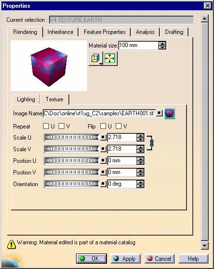
192 Page 192
193 Sorting Materials Within a Family Page 193 This tasks explains how to arrange materials alphabetically within a family in ascending and descending order. Open the SortMaterial.CATMaterial document. 1. Click the Sort Materials (A->Z) icon.


194 Page 194 The materials are automatically arranged in ascending alphabetical order, from left to right and top to bottom: 2. Click the Sort Materials (Z->A) icon to reverse the sort order of materials: You are not obliged to sort materials alphabetically. Simply click on one or more materials and drag them to their new location if you wish to set them in a specific order. You can do this material by material, or use the multi-selection capabilities (Shift and Ctrl keys).
195 Sending Material Texture Images Page 195 This tasks explains how to send images used for material textures in the mail or to a directory or a diskette. Open the SortMaterial.CATMaterial document. Sending in the mail 1. Select the File->Send To->Mail command. The Send To Mail dialog box opens:

196 Page 196 In the upper part of the dialog box you can see a list of all the different documents linked to the document you selected for the send operation. The four columns provide information about the file name, the file type, the location and whether or not the file was found. 2. Select the files in the upper list individually and transfer them to the lower list using the icon. If you want to select the files by type, place the cursor inside the list and right-click to display the list of file types and then select the appropriate type. (Selecting by type in this way operates of course in the lower list as well.) The OK button may be grayed out. This means that problems shown in the Problem column have not been resolved. 3. Click OK. You will now be prompted to give the name of your system.

197 Page 197 For detailed information on using the Send To Directory command, refer to the Version Infrastructure User's Guide - Transferring Version 5 Data To Another Directory. Copying to a directory or diskette 1. Select the File->Send To->Directory command. The Send To Directory dialog box opens:
198 Page 198 In the upper part of the dialog box you can see a list of all the different documents linked to the document you selected for the copy operation. The four columns provide information about the file name, the file type, the location and whether or not the file was found. 2. Select the files in the upper list individually and use the icon to transfer them to the lower list If you want to select the files by type, place the cursor inside the list and right-click to display the list of file types and then select the appropriate type. (Selecting by type in this way operates of course in the lower list as well.). It might be useful, especially if copying files to a diskette, to know the size of the documents to be copied. You will find this just above the Copy to: field. The OK button may, as in the case shown above, be grayed out. This means that problems shown in the Problem column have not been resolved. 3. Enter the path of the target directory in the Copy to: field using the Browse button if necessary and click OK. This field is in fact a list and contains the nine destinations last used. 4. Click OK. A progress box appears as each file is copied and when the copy has been performed, the Files Copied dialog box appears telling you the number, size and type of the files copied. For detailed information on using the Send To Mail command, refer to the Version Infrastructure User`s Guide - Sending Version 5 Data in the Mail.
199 ClearCoat 360 Textures Page 199 Using ClearCoat 360 Textures Generating ClearCoat 360 Textures
200 Using ClearCoat 360 textures Page 200 This tasks explains how to apply a ClearCoat 360 texture. ClearCoat 360 technology is supported for real-time lighting and reflection computation. It reproduces the reflective nature of glossy materials such as paint, plastic and glass. This life-like rendering technology improves greatly the fidelity of styling reviews. You can apply ClearCoat 360 textures (.cc360 extension files) the same way you apply textures to your model: Version 5 Real Time Rendering product lets you create materials with ClearCoat 360 textures Version 5 Real Time Rendering product lets you create a Box environment where you can apply environment textures used by your ClearCoat 360 files. ClearCoat 360 technology is available for IRIX (SGI only). To be able to use ClearCoat 360 technology, download the ClearCoat 360 runtime library (named "libcc360.so") from the following site: This library must be installed in the Version 5 filetree containing runtime code (...code/bin). 1. Open your document then access the material texture properties: 2. Select ClearCoat 360 from the Type pulldown list as shown below:
201 Page In the Image Name field, indicate the name of the ClearCoat 360 texture to be applied or click the button to navigate to the desired file. 4. Click Apply to validate then OK to close the dialog box. The ClearCoat 360 texture is applied. The following picture illustrates the result you can obtain when applying ClearCoat 360 textures:

202 Page 202 If you do not have any ClearCoat 360 texture to apply, you can generate one by yourself. Refer to Generating ClearCoat 360 Textures for detailed information.
203 Generating ClearCoat 360 textures Page 203 This tasks explains how to generate a ClearCoat 360 texture based on 6 images you select representing a cubical scene. ClearCoat 360 technology is available for IRIX (SGI only). To be able to use ClearCoat 360 technology, download the ClearCoat 360 runtime library (named "libcc360.so") from the following site: This library must be installed in the Version 5 filetree containing runtime code (...code/bin). To create ClearCoat files, use the Sphere Maps generator SMGen. SMGen ordering instructions are available from the following site: 1. Open your document then access the material texture properties. 2. Select ClearCoat 360 from the Type pulldown list as shown below:
204 Page Click the icon to open the ClearCoat 360 Texture Generator:

205 Page 205 This dialog box lets you choose the type of ClearCoat 360 texture you want to generate. The tabs displayed below will be accessible according to the type you select, except Quality which is common to all texture types. 4. To create your own environment image, just click each environment wall (i.e. "Up", "Back", etc.) In the upper part of the dialog box then navigate to the desired image using the File Selection dialog box. Note: only rbg and tif formats are supported.

206 Page Choose the type of texture to be generated from the Texture Type pulldown list: Multi-layer Paint to produce a realistic multi-layer paint Lets you access Quality, ClearCoat Layer and Substrate Layer tabs Mirror to produce a perfect BRDF mirror (for Bidirectional Reflection Distribution Function) Lets you access Quality tab Spherical mirror to produce a perfect normal reflector Lets you access Quality tab Phong effect to create a Phong-type render Lets you access Quality and Phong Parameters tabs. Note that only.tif images of type "float" can be used to generate Phong-type textures. To convert your.tif images to this format, you can use a SGI utility which lets you open then re-save your images in TIF float format. As the number of tabs you can access varies according to the texture type you select, here is a description of each tab: 6. Use the Quality tab lets you define the following parameters:

207 Page 207 Super Sampling Corresponds to the sampling number Number of Rays Sets the number of rays to be sent Image Size Sets the texture resolution (either Large, Medium or Small) Viewpoint Precision Defines the viewpoint repartition which is divided into three layers: top, middle and bottom of an icohedron, "0" representing the level of the icohedron. Each value higher than "0" adds a subdivision to the icohedron. 7. Use the ClearCoat Layer tab to define the following parameters: Particle Shape Defines the shape of the ClearCoat 360 particles. It can be either spherical, the the shape of a round platelet or the shape of a square platelet Particle Size Defines the size of the particles in millimeters Particle Density Defines the number of particles per square millimeters Layer Depth Defines the depth of the layer in millimeters Particle Color Lets you define the color luminosity using the slider or the value-entry field. You can also click the white). button to choose another color for particles (the default color is
208 Page 208 Particle Refraction Defines the refraction coefficient for particles, i. e. the degree of light passing through particles. You can enter a value comprised between 1 and 2. If set to 1, there is no light distortion Layer Refraction Defines the refraction coefficient for the layer, i.e. the degree of light passing through the layer. 8. Use the Substrate Layer tab to define the following parameters for the Substrate Layer: These parameters are identical to those displayed under the ClearCoat Layer. Refer to previous step for detailed information. 9. Use the Phong Parameters tab to define the following parameters:

209 Page 209 Ambient Defines the intensity of light diffused in any direction by the object, even if not lit by any light source. You can enter a value comprised between 0 and 1 for this coefficient Diffuse Defines the intensity of light diffused by the object when lit by light sources. You can enter a value comprised between 0 and 1 Specular Defines the intensity and color of light reflected in one particular direction (highlights) Typically, a polished object would have a high value for the specular reflectance coefficient, while a more mat surface would have a lower one Roughness Defines the dullness of the object, i.e. the size of the reflecting zone. Set the value to a minimum to generate very sharp highlights on very shiny surfaces. Set the shininess to a higher value to generate large specular spots creating a duller effect on rougher surfaces Refraction Defines the degree of light refraction passing through the object. You can enter a value comprised between 1 and 2 Light Color Use the slider or the value-entry field to modify the light luminosity, then click the button if you want to choose another color (the default color is white) Light Direction Defines the light direction along X, Y and Z axes to specify the point at which the light source points.
210 Page Once the parameters have been defined, indicate the name and location of the texture to be generated in the Save As field. You can also click the icon then navigate to the desired location. 11. Click OK to validate. A window opens to inform you that the texture computation starts: Once the texture is computed, its name is automatically displayed in the Image Name field in the material texture properties.
211 Advanced Materials Page 211 Using the Car Paint Material Using OpenGL Materials
212 Using the Car Paint Material Page 212 This tasks explains how to use the Car Paint material which lets you apply a metallic texture with reflective-particle effects. This advanced material is hard-coded and delivered with your Version 5 product. The Car Paint shader is available on Windows and SGI only. Moreover, bear in mind that this shader is not taken into account when computing rendered images. To be able to use this advanced material, you need to download the OpenGL Shader development kit. To do so: if you are working on IRIX, browse the following site: then download the corresponding kit. if you are working on Windows, browse the following site: then send an to the Strategic Partner Manager (click its name on the page) to ask for the required elements. You can then open the Hood.CATProduct document. 1. Access the Tools->Options->General->Display->Performances tab then check the "Enable OpenGL Shader" option in the Miscellaneous area:
213 Page Select the Chroma material in the specification tree. 3. Select the Edit->Properties command or right-click and select Properties from the contextual menu to open the Properties dialog box. The material properties can also be accessed by right-clicking the object onto which the material has been applied, then selecting the Material->Edit Material contextual commands. This avoids selecting the material in the specification tree and is especially useful when working in Full Screen mode, for instance. You can also manipulate the object (i.e. zooming in/out, etc.) directly in the geometry area while displaying the Properties dialog box either by double-clicking the material in the specification tree or by selecting Object->Definition... from the contextual menu. Note for light sources: The Car Paint advanced material supports standard light sources (defined via the View- >Lighting... command) as well as spot and directional light sources defined in the Real Time Rendering workbench. When using the above-mentioned light sources, you can modify the specular, ambient and diffuse coefficients as needed. 4. Click the Texture tab then select "Car Paint" from the Type pulldown list:


214 Page 214 The shader is applied to your model as shown below:
215 Page Use the Paint Color field to define the color of the texture either using the slider or the value-entry field. You can also click the... button to define more precisely the color to be applied. This opens the Color chooser: Click in the preview area to choose the color, or even key in the exact value of the desired color. You can enter a value comprised between 0 and 255 for any of these fields. As you can see it in the above picture, two color system models are used: HLS (Hue, Saturation, Luminance) model is an intuitive, easy to use tool for describing or modifying a color. Hue is the "color" of the color. It is the name by which the color is designated and is used to define the desired color. Saturation is the intensity of the color. The higher the number, the more intense the color. It is used to tune the purity of the color. Luminance is the brightness of the color, i.e. the degree to which the pure color is diluted by white or black. The larger the number, the lighter the color. It is used to adjust intensity. RGB (Red, Green, Blue) model is a more physical model. It is based on the tristimulus theory of the human perception system. This model is usually used to define, with a high precision, the three primary components of the color.


216 Page 216 Once satisfied with the color, click OK to validate and go back to the Properties dialog box. 6. The Particle Brightness field lets you define the contrast, i.e. the intensity of light diffused by particles when lit by light sources. You can choose a value comprised between 0 and 1. For instance, "0" means that there will be no particles at all as shown below: Particle brightness = 0 Particle brightness = 1 7. Use the Particle Density field to set the size of the particles. The higher the value, the smaller the particles. Particle density = 1 Particle density = 3

217 Page The Reflectivity field enables you to define the degree of reflectivity of the particles. The higher the value, the more reflective the particles. You can enter a value comprised between 0 and 1. Set to a high value, the object will reflect its environment. Reflectivity = 0 Reflectivity = 0.5 When setting the Reflectivity parameter, you can also click the... button to set advanced reflection settings if you wish to use a customized environment image for environment reflections:

218 Page 218 For more information, refer to Defining Reflection Settings in this guide. Note that, when using the Car Paint shader, the Advanced Reflection Settings dialog box slightly differs from the usual one (the Reflection Type, Transparency Width and Transparency Height fields are not displayed) but works the same way. When finished, click OK to validate and go back to the Properties dialog box. 9. Use the Roughness field to set the size of the specular spot. Set the value to a maximum to generate very sharp highlights on very shiny surfaces. Set the roughness to a lower value to generate large specular spots creating a duller effect.

219 Page 219 Roughness = 0.2 Roughness = Click OK or Apply + OK to validate your parameters and close the Properties dialog box.
220 Using OpenGL Materials Page 220 In this task, you will learn how to apply a specific OpenGL material and modify the associated.isl file containing the material parameters. OpenGL materials lets you create textures such as paint, wood or marble. Some.isl file samples are delivered with their associated image files in your Version 5 but do not forget that you can use and edit your own files to address your needs. OpenGL shaders are available on Windows and SGI only. Morevoer, note that there is a price to pay in memory usage and 128 MB of RAM is the minimum recommended amount of memory when working on SGI. You must also bear in mind that this shader is not taken into account when computing rendered images. To be able to use this advanced material, you need to download the OpenGL Shader development kit. To do so: if you are working on IRIX, browse the following site: then download the corresponding kit. if you are working on Windows, browse the following site: then send an to the Strategic Partner Manager (click its name on the page) to ask for the required elements. You can then open the Chess.CATProduct document. 1. Access the Tools->Options->General->Display->Performances tab then check the "Enable OpenGL Shader" option in the Miscellaneous area:

221 Page Select the Italian Marble material in the specification tree. 3. Select the Edit -> Properties command or right-click and select Properties from the contextual menu to open the Properties dialog box. The material properties can also be accessed by right-clicking the object onto which the material has been applied, then selecting the Material->Edit Material contextual commands. This avoids selecting the material in the specification tree and is especially useful when working in Full Screen mode, for instance. You can also manipulate the object (i.e. zooming in/out, etc.) directly in the geometry area while displaying the Properties dialog box either by double-clicking the material in the specification tree or by selecting Object->Definition... from the contextual menu. Note for light sources: OpenGL advanced materials support standard light sources (defined via the View->Lighting... command) as well as spot and directional light sources defined in the Real Time Rendering workbench. When using the above-mentioned light sources, you can modify the specular, ambient and diffuse coefficients as needed. 4. Click the Texture tab then select "OpenGL Shader" from the Type pulldown list: 5. Click the icon which lets you browse your file tree to select a.isl file then click Open. This displays the parameters declared in the.isl file, each field corresponding to one parameter. In our example, we use one of the sample files named "shiny_wood.isl" provided in $CATStartupPath\startup\materials\shaders:


222 Page 222 The shader is applied to your model as shown below:
223 Page Adjust the parameters displayed as desired. The modifications you made are automatically applied to your model to let you check the result. In our example, we can modify how the texture is stretched along u-, v- and w- axes by changing the values displayed in the base_texture_scale1, 2 and 3 fields. 7. Click OK or Apply then OK to validate your parameters and close the Properties dialog box. The parameters will be stored in the model with the material and not in the.isl file. If you edit the material parameters using a non-version 5 application then re-access the material properties in Version 5, a warning window pops up to inform you that the parameters declared in the.isl file supersede any other data you may have stored in the material (and thus, these data will be lost). 8. If you want to modify the parameters declared in the.isl file, just open this file in any text editor such as WordPad, Notepad, etc. The text looks like this:
224 Page 224 You can then edit the text as you wish to modify existing parameters or create new ones. Making complex modifications implies that you are familiar with the SGI language. If this is not the case, you can still make basic changes which do not require particular knowledge of the SGI language. For instance, you could change the texture associated to this shader by replacing the file "wood.rgb" with the texture file of your choice. Note: all image formats are supported for texture files. 9. Save your.isl file when finished then go back to your Version 5 session to apply this shader to your object. It is recommended that for the sake of convenience you save your texture file and your.isl file in the same location. Below is an example of what you can get using the Car Paint shader. Click the thumbnail to see the fullsize picture: The following are samples of the various.isl files provided. Just click the desired thumbnail to display it in full-size: Advanced Car Paint Car Paint Generic Material Green Marble Shiny Wood Wood Tile Mat Brushed Metal Shiny Brushed Metal
225 Using Virtual Reality Page 225 About Virtual Reality Support in Version 5 Running a Multipiped Version 5 Session Working With the Immersive System Assistant
226 About Virtual Reality Support in Version 5 Page 226 What is Virtual Reality? Clicking and dragging your way through a 3D graphics application may be interactive, but it's not virtual reality. It's not Virtual Reality because it's not immersive. "Immersion" (or "presence") is the goal of virtual reality. Immersion refers to your sense of engagement with the virtual model or environment. When you're immersed, you focus directly on your subject and disregard everything else. In virtual reality, an "immersive" application lets you focus on the task at hand, so you don't deal with a mouse, or the UNIX command line, or a GUI, or the fact that you're actually looking at something made from digital bits instead of physical atoms. Virtual reality essentially moves the computer out of your way, so you can interact directly with your data or information. Unlike interactive 3D graphics (which can consist of a series of still images coming off disk), virtual reality lets you intuitively manipulate and navigate through a realtime simulation of an object, or a process, or a place. Where is Virtual Reality technology useful? Virtual reality adds value to virtually any application where it's vital to experience spatial relationships, and analyze, design, engineer and understand such relationships. Any project in which 3D information must be navigated or closely examined will benefit from virtual reality technology. If you are working in two dimensions (web design, word processing,...), you don't need virtual reality. What are the different types of Virtual Reality configurations?
227 Page 227 Virtual reality technology can be recognized by the presence of specific I/O devices which can be organized into five categories, each creating a different impression of immersion. These categories are not mutually exclusive: Simulators Simulators use a physical mockup of vehicle with real controls (steering, throttle, pedals, etc.), with which you can navigate through virtual environment, and are ideal for applications such as pilot training, driver training and games. Simulators can also involve multiple participants. Wearable devices Wearable devices provide direct, "body contact" input/output to virtual models or environments through such devices as head-mounted displays, boom-mounted displays, data gloves, data suits, haptic feedback systems, motion platforms. These are ideal for digital prototyping, and provide a highly immersive experience. However, they are limited to single users. Desktop devices The traditional monitor serves as a window into virtual world, with which you interact using shutter glasses and 3D input. This is a low-cost alternative to wearable devices, and are suitable for scientific data visualization. They are also flexible (easily switch from monoscopic to stereoscopic; easy keyboard access). This range of equipment includes stereoscopic workbenches, tables and desks. However, desktop devices suffer from the following drawbacks: they are based on the single user approach they do not provide a full immersion experience. External devices External devices are used to interact with your Version 5 session. Those devices consist of a hand held equipment in which a tracker and a set of buttons have been integrated. Hand tracking allows you to add a virtual hand in the model to perform interactive functions such as selection, command run or navigation. Display systems Large virtual models and environments are projected onto flat or curved screens, using such technologies as virtual reality walls (for example, in Silicon Graphics Reality Centers). They can also be projected onto vertical and/or horizontal surfaces in special chambers like "caves" (for example, the Fakespace CAVE) or "walk-in domes". These devices are the most sophisticated (and most expensive). They are ideal for digital
228 Page 228 prototyping, provide high resolution, and allow groups of participants to get involved and collaborate. They also require a lot of physical space. Which Virtual Reality tools/technologies can be used in Version 5? In the myriad of tools and configurations available, we can already identify a short-list of hardware useful for navigating through or manipulating CAD data in real time, and capable of providing some level of immersive experience: Stereoscopic viewing Stereoscopic viewing of 3D images is built in Version 5. It can be achieved either in active or passive stereo mode, depending on the display system abilities. In an active stereo display system, left eye and right eye images are alternatively displayed on the screen at twice the refresh rate. An active pair of glasses with two shutters working in synchronization with the images is needed. Synchronization is often achieved using an infrared emitter: the left eye shutter is closed when the right eye image is displayed, and reciprocally. In a passive stereo display system, left eye and right eye images are displayed simultaneously on the screen. Image separation is performed by filtering glasses using polarized light, for instance. Stereoscopic viewing is extremely easy to implement. All hardware manufacturers provide now graphic boards supporting OpenGL quad-buffered stereo on Windows and UNIX based systems. Stereoscopic shutter glasses, such as the CrystalEyes manufactured by StereoGraphics, provide a partially immersive experience of digital mock-up visualization at lowest price investment. Another possibility is to use a StereoGraphics Z-Screen mounted on top of a standard monitor and viewed wearing nonexpensive and lightweight passive stereo glasses. Head mounted display Head mounted display (HMD) afford a more immersive experience. Equipped with position-tracking capability, it displays output imagery based upon the position of your head. To use a head mounted display, you can have either: an image generator computing left eye and right eye image separately such as an SGI Onyx workstation. Those are high-end systems providing high performance and high quality 3D viewing or
229 an active to passive stereo converter such as Cyviz XPO2 box. This solution allows you to use an head mounted display on any platform supporting active stereoscopy. Page 229 In addition to head mounted display, a standard joystick can be added to the virtual reality configuration, providing a very easy way to navigate in the digital mock-up. Projector tables, projection walls, Immersive Rooms Digital prototyping is served well by using a large projection systems going from the single screen projection table, such as Fakespace Systems ImmersaDesk or Barco Baron, to the multi-projector and multi-sided projection room, such as the FakeSpace Systems CAVE or the Barco I-Space. Version 5 also supports reconfigurable immersive display systems such as the Fakespace RAVE or the Barco MoVE. Those systems are ideal for scale one digital mock-up review or designing large assemblies and facilities. Displaying the Version 5 on a single screen/single projector display system requires no specific Version 5 service. You just need to plug your machine graphic board video output to the display video input. When you have a multi-projector display system, for instance as in a TAN Holobench or in a SGI Reality Center, you need a specific hardware and specific Version 5 functionalities. Using a multipipe SGI Onyx workstation, Version 5 can support any kind of immersive environment, that is to say any number of screens and projectors, in passive or active stereo vision mode. In such environments a better immersion is achieved using head tracking, providing a 3D image depending on the exact user point of view, as well as hand tracking for immersive interaction. To do so, Version 5 supports: Trackers such as Polhemus Fastrak, Intersense IS-900 and any devices compliant with the Fastrak Protocol Hand held devices with integrated tracker and buttons such as Virtual Presence SpaceStick, Fakespace Neowand or Intersense Wand 3D Connexion Spaceball and Space Mouse which could dramatically increase your work productivity by helping you manipulating the model with your second hand. Please note that those devices are not specific to virtual reality and can be used in any standard desktop configuration. What does Version 5 support natively?
230 Page 230 The Version 5 infrastructure provides support for: stereoscopic viewing: refer to Stereoscopic Viewing for more information multipipe and multithread rendering: refer to Running a Multipiped, Multithreaded Version 5 Session for more information head and hand tracking: refer to Using Head and Hand Tracking Devices in Version 5 for more information.

231 Running a Multipiped Version 5 Session Page 231 In About Virtual Reality Support in Version 5, we discussed the different types of virtual reality configurations available. However, intensive use of virtual reality technology leads to loss of performance if you are using only one graphics pipe. What is a "pipe" and what is the difference between a single and multipipe system? A "pipe" in this context refers to the graphics board associated with each single window into an application. It also refers to the data that is placed by the application which owns the pipe. You can also have a single pipe feeding three display channels like this: Nothing prevents you from using virtual reality configurations with just one pipe, the problem is that the overhead of running multiple applications in a single piped system can result in very poor performance. In a "multipipe" system, you can have several graphics boards, and each graphics board feeds a different display channel. Each application in a " multipipe" system has its own distinct pipe to the graphics hardware. There is a price to pay in memory usage and a very slight price to pay in computer overhead to manage the multiple pipes, but the overall positive effect on system performance is dramatic. Performance can be enhanced even further if you are running workstations using multiple processors, which allow "multithreading" of applications. Note that: the Version 5 infrastructure for UNIX platforms provides support for 16 windows maximum one window/pipe can be assigned to two threads (2 CPUs). A typical configuration is an SGI Onyx2 or SGI Onyx 3000 workstation using four graphics pipes. You run a main Version 5 session using one pipe from a workstation, and create three secondary windows (each one using its own graphics pipe) for projection onto a Reality Center-type projection screen, or inside a virtual reality CAVE. 1. Log onto the Onyx workstation.
232 Page Run the following command to display graphics subsystem information about your configuration: /usr/gfx/gfxinfo This command displays information (display name, resolution, etc.) about each graphics pipe like this: Graphics board 0 is "KONAL" graphics. Managed (":0.0") 1280x Graphics board 1 is "KONAL" graphics. Managed (":0.1") 1280x Graphics board 0 is "KONAL" graphics. Managed (":0.2") 1280x Graphics board 1 is "KONAL" graphics. Managed (":0.3") 1280x Synchronize the graphics pipes with the video channels in your configuration by running the program: /usr/gfx/ircombine Refer to your IRIX documentation for more information about the ircombine program. 4. Export one of the following environment variables: export CATMPConfig=path/myconfigfile or export CATMPKConfig=path/myconfigfile where "path" is the path of a directory and "myconfigfile" is the name of a configuration file which you must create and edit to set up the secondary windows and assign them to different graphics pipes and displays. Version 5 supports OpenGL Multipipe SDK technology (MPK) as well as an older set of SGI multipipe services. The MPK library is developped by SGI to manage multi-channel display configurations. Version 5 mpconfig command switches on and off the Version 5 multichannel support. The prerequisite is that one of the environment variables, i.e. CATMPKConfig or CATMPConfig, is valuated to a configuration file path before running the application: if CATMPConfig is valuated, the command activated the old set of multipipe services if CATMPKConfig is valuated, the command activates the MPK support.
233 Page 233 Using MPK Version 5 provides powerful support for many virtual reality configurations: active or passive stereo decompositions, such as Stereo (Eye), DPLEX, 2D all multi-screen/multi-projector configurations such as TAN Holobench, Fakespace CAVE, etc. viewpoint tracking on all screens. Note: in order to use MPK, you need to download the corresponding library. For detailed information, browse the following internet site: When turned on using the mpconfig command, the multipipe support displays an information window (named "Multi Pipe started") in which you just have to click OK to proceed. Some additional windows will then appear on the managed piped and the Version 5 model will be displayed across all windows. These two variables are not compatible and if you export both of them, the CATMPConfig variable supersedes the CATMPKConfig variable. 5. Edit the configuration file. If the display ":0.0" is used for the main Version 5 session, the syntax of the following file shows how to project a session using three separate pipes and the CATMPConfig environment variable : pipe { name ":0.1" window { x 0 y 0 width 1280 height 1024 reference wall_position [0,0] 0,0 } } pipe { name ":0.2" window { // First pipe declaration // Display name // First window declaration //Horizontal position (in pixels) //Vertical position (in pixels) //Window width (in pixels) //Window (in pixels) //Use width and height of this window to compute all size parameters //Define the wall position (in pixels); the center of the main window is // Second pipe declaration // Display name // Second window declaration
234 x 0 //Horizontal position (in pixels) y 0 //Vertical position (in pixels) width 1280 //Window width (in pixels) height 1024 //Window height (in pixels) Page 234 wall_position [1280, 0] } } pipe { name ":0.3" window { x 0 y 0 width 1280 height 1024 // Third pipe declaration // Display name // Third window declaration //Horizontal position (in pixels) //Vertical position (in pixels) //Window width (in pixels) //Window height (in pixels) wall_position [-1280, 0] } } 6. Save your changes to the configuration file, then start your main Version 5 session. 7. In your main session, run the command: c:mpconfig to start multipiping. This creates the three empty secondary windows whose display name, size and position you defined in the configuration file. If you are using a Reality Center-type projection screen, for example, the three windows will be displayed side-by-side. 8. In your main session, run the command, select the command View->Full Screen. The video output displayed inside your main session is now projected coherently across the three windows. 9. In your main session, run the command: c:mpconfig again to stop multipiping.
235 Page 235 Note that you can use stereoscopic viewing from within a multipiped session. Note also that in CAVE configuration, you can increase the specular lighting accuracy by checking the "Enable OpenGL local viewer lighting" option in Tools->Options->General->Display->Performances. Be aware that this may lead to a loss of performance. Calibrating the multi-channel support First of all, let's remind us of the SGI pipe and channel architecture. An SGI machine as an Octane or an Onyx may host several graphic boards, named pipes. A same application can render images on all of these pipes. A pipe has a frame buffer in which the application write the images they compute. More precisely, each application writes images in windows that are sub-parts of the frame buffer. On the video output side, the system reads the pipes frame buffer and generate video signals. There is one video signal per active channel. Each pipe may host several channels. Each channel is positioned on a part of a pipe frame buffer, and a video signal generated display this particular part. The important caracteristic of the system is the number of pipes, their frame buffer size (called "managed area"), the number of channel per pipe, their corresponding frame buffer sub area and the video signal format they output. You get the system information by typing /usr/gfx/gfxinfo in a shell. You can modify your system configuration using the "setmon" or "ircombine" commands. They enable you to change the pipe-managed area size, the activated channels on each pipe, their frame buffer part as well as their video format. Report to the SGI documentation to use these commands. The pipes are usually named ":0.0", ":0.1", ":0.2"..., unless you have several X Servers, in which case they are named ":0.0", ":0.1"... on X Server 0, ":1.0", ":1.1",..., on X server 1...
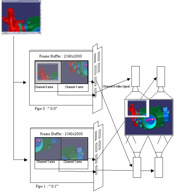
236 Page 236
237 Page 237 On the scheme above, the system has two pipes and six channels per pipe. Only two are activated on each pipe. The pipe-managed areas are 2560x2000. The Pipe 0, channel 0 is associated to an area of size 1280x1024, and located at the coordinate (0,0). The Pipe 0, channel 1 is associated to an area of size 1280x1024, and located at the coordinate (0.5,0). The Pipe 1, channel 0 is associated to an area of size 1280x1024, and located at the coordinate (0,0). The Pipe 1, channel 1 is associated to an area of size 1280x1024, and located at the coordinate (0.5,0). The channel video format are 1280x1024 at 96Hz stereo for instance. Version 5 renders 3D images in four windows. Two of them are on pipe 0, and the other two on pipe 1. Among these windows, one is particular: this is the main document window which appears within the application frame. The other windows are called "auxiliary windows". If the user goes to the "FullScreen" mode, a complete image of the model will appear on the screen. All the information Version 5 needs for such a configuation are in a configuration file (refer to SGI MPK support). However, the system should also be correctly set up using the "ircombine" or "setmon" commands. Also, since this system outputs active stereo, the pipes need to be "genlocked". This means that their video refresh are synchronized. This is necessary for the stereo glasses to work corrrectly. You should refer to the SGI support for genlocking your system. For instance, to set up the system, you can run the following script in a shell. You need the administrator privileges. This script will log you out and may badly affect the system if there is an error in it. echo "Pipe 0 INTERNAL (master). Setting..." /usr/gfx/ircombine \ -target :0.0 \ -destination eeprom \ -global syncsource=internal,size=2560x2000 \ -channel 0 format=1280x1024_96s,sync=rgb,sourceloc=0+0 \ -channel 1 format=1280x1024_96s,sync=rgb,sourceloc= echo "done." echo "Pipe 1 EXTERNAL (slave). Setting..." /usr/gfx/ircombine \ -target :0.1 \ -destination eeprom \ -global syncsource=external,syncformat=1280x1024_96s,size=2560x2000 \ -channel 0 format=1280x1024_96s,sync=rgb,sourceloc=0+0 \ -channel 1 format=1280x1024_96s,sync=rgb,sourceloc= echo "done." echo (/usr/gfx/stopgfx;/usr/gfx/startgfx)&
238 Page 238 There are two kind of configuration file you can use to deal with multi-channels configurations. We only speak here about the MPK config file. To run V5 with such a configuration file, type in a shell: export CATMPKConfig={complete path of the config file}. then, in this same shell, run CATIA : /usr/dassaultsystemes/bn/irix_a/command/catstart -env {EnvName} -direnv {environment path name} where "n" is the release number. The "Mpconfig" command will use the configuration file pointed by the CATMPKConfig environment variable.to have a full undertanding of the MPK config file format, please refer to the MPK documentation. Only a standard display configuration will be taken as an example and detailed here. Let's assume we have a cubic immersive space such as a Fakespace CAVE, or a Barco Cubic Immersive Space. This system has four walls. All of them are square. The length of each square side is 3 meters long. There are four projectors displaying active stereo (one projector per wall). The machine has two pipes and six channels per pipe. It is set (ircombine) so that: The pipe-managed areas are 2560x1024 Pipe 0 channel 0 goes to the front wall. Its size is 1280x1024. Its location is (0,0) Pipe 0 channel 1 goes to the right wall. Its size is 1280x1024. Its location is (1280,0) Pipe 1 channel 0 goes to the left wall. Its size is 1280x1024. Its location is (0,0) Pipe 1 channel 1 goes to the floor. Its size is 1280x1024. Its location is (1280,0) The mpk file writes as follows: global { MPK_WATTR_PLANES_ALPHA 1 MPK_DEFAULT_EYE_OFFSET 57 MPK_WATTR_HINTS_STEREO 1 MPK_DATTR_QUADSTEREO_HEIGHT 768 This is the global section where you set some global options. Always specify the MPK_WATTR_HINTS_STEREO option when using stereo. Set thmpk_dattr_quadstereo_height and MPK_DATTR_QUADSTEREO_WIDTH to your manage area size when using stereo. } MPK_DATTR_QUADSTEREO_WIDTH 1024 Set the "mode" to "stereo" or "mono" to activate or not the stereoscopic rendering. config { name "Config" mode stereo mono [ "", none ] Declare the pipes you are using and specify their name. In each pipe section, declare the windows Version 5
239 stereo [ "", quad ] pipe { } display ":0.0" window { name "left window" viewport [0, 0, 1, 1 ] channel { } name "left view" viewport [ 0., 0., 1., 1. ] wall { bottom_left [ , -1524, ] bottom_right [ , -1524, ] top_left [ , 1524, ] } window { name "front window" Page 239 will manage on these pipe (including the main document window). The main document window should always appear first in its pipe. If your run Version 5 in pipe X, the main document window will use the paramaters of the window declared first in the pipe X section of the configuration file. The window viewport specifies the window size and position within the pipe frame buffer. The figures correspond to a ratio of the managed area size : [x,y,width.height]. You should always declare one channel per window, and only one (Version 5 only support on channel per window). The term channel may be confusiong since it does not have the same meaning as the usual pipe channels. Just always declare the channel viewport as [0,0,1,1]. Then, specify the coordinates of the wall corners. This window image will then be supposed to be projected onto the corresponding wall, fitting exactly the rectangle described by the coordinates. The coordinates should be expressed in the MPK reference frame. Use the same unit as the unit. The default eye position is defined by this reference frame. This means that if you use the "MPConfig" command without head tracking, the point of view will be computed for a user standing with its head at this reference frame origin, looking along its -Z axis, and with its right on the positive X axis side. Since it is usually better to define the system front wall as the one naturally seen by the default head position, the MPK reference frame is chosen so that this front wall is on its -Z axis side. viewport [0, 0, 1, 1 ] channel { name "front view" viewport [ 0., 0., 1., 1. ] wall Bear also in mind that the interaction with the model is only possible within the main window. In particular, this is the case of the viewpoint manipulation with the mouse. Thus, the front wall is usually set as the main document window. Here, we get : { bottom_left [ , -1524, ] bottom_right [1828.8, -1524, ] top_left [ , 1524, ] } } }
240 Page 240 } pipe { display ":0.1" window { name "right window" viewport [0, 0, 1, 1 ] channel { name "right view" viewport [ 0., 0., 1., 1. ] wall { bottom_left [1828.8, -1524, ] bottom_right [1828.8, -1524, ] top_left [1828.8, 1524, ] } } } window { name "floor window" viewport [0, 0, 1, 1 ] channel { name "floor view" viewport [ 0., 0., 1., 1. ] wall { bottom_left [ , -1524, ] bottom_right [1828.8, -1524, ] top_left [ , -1524, ] } } }
241 Page 241 Working With the Immersive System Assistant In this task, you will learn how to access and use the Immersive System Assistant workbench in order to configure your Virtual Reality devices and display system. Within this workbench, the various elements (screens, trackers, etc.) any reality center hardware installation is made of are graphically represented and this visual feedback enables you to create, edite and delete very easily the necessary data. These data will then be used to generate automatically an XML configuration file via a command provided by the Immersive System Assistant workbench, thus avoiding a "painful" manual edition. From V5R13 onwards, all drivers and brokers supported by Version 5 are threaded which means that there is no need to run external processes anymore. In addition to that, all the necessary MPK display configuration data (including those related to the threaded brokers and drivers) are now grouped together into a single configuration file saved in XML format. These data will then be used when starting up your Version 5 session to run the broker and the driver automatically with the appropriate configuration. However, note that you can still run drivers and brokers manually as before if needed, for instance when using external drivers or when running a driver on a remote machine. Real Time Rendering 2 (RTR) users can access and use the Immersive System Assistant workbench. However, a P3 licence is required to be able to use tracking stations and trackers. 1. Access the Immersive System Assistant workbench by selecting the Start menu then Infrastructure- >Immersive System Assistant. The Immersive System Assistant workbench opens:

242 Page 242 This workbench lets you create and manipulate several types of objects: graphic board (or IG for "image generator") window view (either screen or camera) head hand picking device tracking station tracker. Note that the head, the hand picking device and the trackers are automatically managed and thus, cannot be deleted. 2. Click the New IG icon to create a graphic board (you can modify the default name by entering a new name in the Display field):

243 Page Click the Toggle the plan view on icon to display the graphic board symbol in the current window. You can then hide the graphic board by clicking again this icon. 4. Repeat steps 2 and 3 to create another graphic board and display it in the current window. The geometry area now looks like this: 5. You will now create a rendering specification by clicking the New View icon. This opens the View Properties dialog box which lets you define the type of view you wish to use as well as its properties:
. Screen View 1.")
, respectively.")
244 Page 244 You can choose between a screen view or a camera view: screen: use it when the viewpoint to render is defined by the user moving in front of a fixed screen camera: use it when the viewpoint to render is attached to the head of the user, like a camera (such as a head-mounted display). Screen View 1. Click the tab you will use to set the screen properties, either: Screen Corners Enter the coordinates of three screen corners (upper left corner, lower left corner and lower right corner) Field of view The H fov and V fov fields represent the horizontal and vertical field of view (in degrees), respectively. The H shift and V shift fields lets you translate the screen horizontally and vertically. The Head field defines the horizontal rotation of the screen around the head. The Pitch field defines the vertical rotation of the screen around the head. The Distance field defines the distance (in millimeters) to the head.

245 Page 245 Screen size The Width and Height fields correspond to the screen width and height, respectively. The Head field defines the horizontal rotation of the screen around the head. The Pitch field defines the vertical rotation of the screen around the head. The Center area lets you set the coordinates of the screen center. Once you entered values in a tab, the values of the two other tabs are automatically updated accordingly. You can then pass from one tab to another very easily. Camera View 1. Click the Frustum tab: "Frustum" is a truncated pyramid representing the angular definition of the field of view for a distance equal to 1. Enter the desired values in millimeters for Left, Right, Top and Bottom. 2. Click the Field of view tab: The H fov and V fov fields represent the horizontal and vertical field of view (in degrees), respectively. The H shift and V Shift fields lets you translate the screen horizontally and vertically. 6. Click OK when satisfied with your screen definition.


246 Page Repeat steps 5 and 6 to create another screen view. Note: you can modify the screen properties at anytime by double-clicking the screen in the geometry area or in the specification tree. The result looks something like this (depending on the values you enter): 8. Click the Snap icon to snap one of the screens to the other. To to so, select an edge of the screen to be snapped then an edge of the other screen:


247 Page 247 You can also snap the 3D compass to a screen view to manipulate it very easily as shown below: Note that the compass cannot be snapped to camera views. The next step is to render the specifications in a window. A window can be defined as an OpenGL rendering zone for a defined viewpoint and is located in the graphic board frame buffer. The specification of the viewpoint to render in a window is called a "view". As a consequence, each window points to a view, either a screen view or a camera view depending on the viewpoint to render. 9. Click the New Window icon to open the Window Properties dialog box:
. 11.")
248 Page Give a name to the new window (or leave the default name) and set is as your referenced window by clicking the Main Window option. The main window is the window which is always visible in Version 5 (the other windows being created "on the fly" when you run the mpconfig command). 11. Select the associated graphic board in the geometry area or in the specification tree. The IG field will be automatically updated accordingly. 12. Select the view the window will point to. The View field will be automatically updated accordingly. 13. In the Viewport area, indicate the portion of the graphic board you are going to use. To do so, enter the desired coordinates in the Left, Top, Width and Height fields means the view will be located in top left corner 1.00 means the view will be located in bottom right corner.
249 Page 249 Default window User-defined window Left=0.00 Top=0.00 Width=1.00 Height=1.00 Left=0.33 Top=0.15 Width=0.57 Height= Specify the Rendering Mode: Mono: only the cyclop viewpoint is rendered Left and Right eye: these modes are used for passive stereo display systems in which left eye and right eye images are displayed simultaneously on the screen. Image separation is performed by filtering glasses using polarized light, for instance Active Stereo: left eye and right eye images are alternatively displayed on the screen at twice the refresh rate. An active pair of glasses with two shutters working in synchronization with the images is needed. Synchronization is often achieved using an infrared emitter: the left eye shutter is closed when the right eye image is displayed, and reciprocally. 15. Use the Mirror Mode field if you want to create a symmetry and define the axis with respect to which the reflected image should be inverted. Note that you can also create a symmetry using the projector. 16. Click Apply then OK to validate and close the dialog box. Now let's go to modifying the head properties! 17. Double-click either the head in the geometry area or the Head item in the specification tree to open the Head edition dialog box:
 along X, Y and V axes define the head orientation in the Heading field set the vertical rotation of the head in the Pitch field set the horizontal rotation of the")

250 Page 250 indicate the distance (in millimeters) between left eye and right eye in the Inter pupillary distance field the Type field is relevant only when working with devices such as trackers define the Head position (in millimeters) along X, Y and V axes define the head orientation in the Heading field set the vertical rotation of the head in the Pitch field set the horizontal rotation of the head in the Roll field. The head position and orientation you define in this dialog box correspond to the default head position and orientation relative to the screens when the head is not tracked. 18. Click OK to validate. If you do not use trackers, it is now time to generate your configuration file. For those who use trackers, a few additional operations need to be carried out before generating the configuration file. Skip the steps below and jump to step Click the Configure VR System icon. The following dialog box appears:

251 Page 251 The Generate VR Configuration dialog box lets you: choose the directory where the configuration file file will be saved. You can either enter a path directly in the field or click the the Browse button then navigate to the desired directory set the configuration as the current one by clicking the "Set as current VR Configuration" option: this means that this configuration will be used to run the driver and the broker when restarting your session add the configuration to the list of configurations displayed in the Tools->Options->General- >Devices and Virtual Reality->Calibration tab. Note that the configuration name cannot be modified in this dialog box. To modify the name, double-click the configuration in the specification tree then, in the VR Configuration Properties dialog box, replace the default name "Config" with the new name before clicking OK: 20. Click OK to validate and close the Generate VR Configuration dialog box. The XML file is generated and saved in the directory you specified. A warning message informs you that you need to restart your session to take this modification into account. 21. Exit your Version 5 session. 22. Restart a Version 5 session which is now correctly configured. 23. Key in the following command in the power input field: c:mpconfig You are now ready to start! If you want to use trackers, here are the additional steps you need to follow:

252 Page Click the Create New Tracking Station icon to create the tracking station your trackers will be associated to and to define the type of tracker to be used. The tracking Station Properties dialog box opens: 25. Type a Name (or leave the default) then specify the Type of the driver you intend to use (either Polhemus or IS900), serial communication Port number the driver is connected to as well as the communication Baud Rate on the serial port. You can now choose a Flock of Birds or ART driver in the Type list. Note: in case you choose a Version 5 compatible driver of your own (i.e. a "Custom" type), a new field will appear to the right asking you for the corresponding daemon name. 26. Indicate the Position of the tracking station. 27. Indicate the tracking station: orientation in the Heading field vertical rotation in the Pitch field horizontal rotation in the Roll field.


253 Page In the Trackers area, identify the trackers to be connected to the tracking station by checking the corresponding figure. Once you validated the tracking station definition, the tracking station and the trackers it is associated to are displayed in the geometry area. In our example, we created a tracking station with two trackers: 29. Double-click the head in the geometry area or the Head item in the specification tree to open the Head edition dialog box then specify the head type. The next step is to edit the tracker. To do so: 30. Double-click the tracker symbol in the geometry area or the number of the tracker you wish to edit in the specification tree. This opens the Tracker Edition dialog box:
254 Page Select the Tracked Element from the pulldown list. The tracker may be attached to the head, the hand or another device. When several trackers are associated to the tracked element, activate the Viewpoint Manager option to indicate which tracker will be used. For hand tracking, this option is named Picking Manager. A tracker may be set as "Button Manager" when this tracker can also be used as a button device (for instance the IS900 or the ART tracker). Checking this option means that the button device will be used by the VRCursor command. When the tracked element is selected, the tracker is attached to the corresponding element symbol in the geometry area and the color of the sphere changes according to the type of tracking: Hand tracking Head tracking 32. If you are tracking hand or head, click the button to automatically generate the matrices and set the standard, i.e. right, position for the tracker depending on the type of tracking station and tracked element. The tracker symbol may be grayed and dotted if the matrices can be automatically calculated and if the information you entered does not match those we recommend. If you want to define by yourself the tracker position, jump to the next step.

255 Page If you choose a "custom" tracker, the position and orientation data define the virtual tracker viewed by Version 5. These data correspond to the offset of the virtual tracker in relation to the physical tracker. The orientation: button is activated to let you define the tracker position in the device as well as its the Heading field lets you define the tracker orientation the Pitch field lets you define the vertical rotation the Roll field lets you define the horizontal rotation. 34. Click the New Button Device icon to access the Button Device Properties dialog box: You have to specify the following information: enter the name of the button device in the Name field select the device type in the Type pulldown list: CUSTOM, Mike, NeoWand or SpaceStick indicate the Dameon name. Button Manager: check this option if you want the button device to be used by the VRCursor command. This capability is relevant for hand button devices onto which a tracker has been fixed, such as the Fakespace Neowand, the Virtual Presence SpaceStick, the ICIDO Mike, etc. In that case, you need to define a button device independently from the tracker. 35. Generate the configuration files by clicking the Generate Configuration Files icon. For detailed information, refer to step 19 and repeat steps 19 to 22.

256 Page The next step depends on the driver and broker you are using: if you are using a non-threaded broker and driver, you need to run them manually using the generated XML configuration file. The broker must be run first then, the driver. For detailed information on the commands to run, refer to Head Tracking or Hand Tracking according to the type of tracking you want to perform. Then, you can restart a Version 5 session if you are using a threaded broker and driver, you can directly restart a Version 5 session: the driver is automatically run with the appropriate configuration. 37. In your Version 5 session, click the Test viewpoint and VR cursor tracking icon to test either hand or head tracking, or even both if needed. The Test tracking window appears and indicates for which tracking the current session is configured: 38. Specify the type of tracking you want to test (if your session is configured for both head and hand tracking) then click the Start button to validate. As you use your tracking device, the tracker representation will move accordingly on screen.
257 Page 257 Working with ENOVIA LCA: Optimal CATIA PLM Usability When working with ENOVIA LCA, the safe save mode prevents the user from creating or editing data in CATIA that cannot be correctly saved in ENOVIA LCA. Working in this mode means that certain commands are unavailable (i.e. grayed) as you enter the Real Time Rendering 1 or the Real Time Rendering 2 workbench. ENOVIA LCA offers two different storage modes: Workpackage (Document kept - Publications Exposed) and Explode (Structure Exposed - Document not kept). Below are listed the commands along with their accessibility status in Explode mode and, in some cases, the rules that are applied to the restricted commands. Command Accessibility in LCA (Explode mode) Warning/Comment RT1 RT2 Apply Material YES (restricted use) Materials with textures are stored without the associated texture image. Materials applied onto products are not saved when closing the session Edit material properties YES (restricted use) Materials with textures are stored without the associated texture image. Materials applied onto products are not saved when closing the session Apply Sticker NO (grayed) Edit sticker properties NO (grayed) Create Spot Light NO (grayed) Create Point Light NO (grayed) Create Directional Light NO (grayed) Edit light properties Create Box Environment Create Sphere Environment Create Cylinder Environment NO (grayed) NO (grayed) NO (grayed) NO (grayed)
258 Page 258 Edit environment NO (grayed) properties Create Camera YES (restricted use) Cameras are not saved when closing the session Edit camera properties NO (grayed) Simulation Create Turntable NO (grayed) NO (grayed) When working in Workpackage mode (Document kept - Publications Exposed), all the abovementioned commands are available.
259 Workbench Description Page 259 Real Time Rendering 1 Real Time Rendering 2

260 Real Time Rendering 1 Page 260 The Material Library Version 5 application window looks like this: Click the hotspot to see the related documentation: Menu Bar Material Library Toolbar Quick Reference Card


261 Menu Bar Page 261 This section presents the menu bar tools and commands dedicated to the Material Library workbench. Start File Edit View Insert Tools Windows Help Edit For... See... Paste Special... Copying & Pasting Using Paste Special... Search... Finding Materials Links... Modifying Materials Properties Modifying Materials Insert For... See... New Family Creating a Material Library New Material Creating a Material Library
262 Material Library Toolbar Page 262 See Creating a Material Library See Creating a Material Library See Creating a Material Library See Creating a Material Library See Creating a Material Library See Creating a Material Library See Modifying Material Lighting Properties and Modifying Material Texture Properties See Sorting Materials Within a Family See Sorting Materials Within a Family
263 Page 263 Quick Reference Card Material Library Create a Family Scenario In the Material Library workbench, click the icon to create a new family. Rename a Family Scenario In the Material Library workbench, select the family to be renamed then click the icon and enter the new family name. Remove a Family Scenario In the Material Library workbench, select the family to be removed then click the icon. Create a Material Scenario In the Material Library workbench, select a family then click the icon to add a material. Rename a Material Scenario In the Material Library workbench, select the material to be renamed then click the icon and enter the new material name. Remove a Material Scenario In the Material Library workbench, select the material to be removed then click the icon. Sorting Materials Scenario In the Material Library workbench, click the icon to arrange materials in ascending alphabetical order, from left to right and top to bottom. In the Material Library workbench, click the icon to arrange materials in descending alphabetical order.
264 Page 264 Modify a Material Scenario In the specification-tree, right-click the material to be modified then click the icon. or In the specification-tree, right-click the material to be modified then select the Edit->Properties... command. or In the specification-tree, right-click the material to be modified then select Properties from the contextual menu. Apply Material Apply a Material Scenario Select the element onto which the material should be applied then click the icon and choose a material from the Library.

265 Workbench Description Page 265 Real Time Rendering 2 The Real Time Rendering 2 application window looks like this. Click the hotspots to see the related documentation: Menu Bar Scene Editor Toolbar Animation Toolbar Apply Material Toolbar Viewpoint Toolbar Light Commands Toolbar Quick Reference Card

266 Menu Bar Page 266 This section presents the menu bar tools and commands dedicated to the Real Time Rendering 2 workbench. Many other operations are documented in the Version 5 Infrastructure User`s Guide. Start File Edit View Insert Tools Windows Help Start The Start menu is a navigation tool intended to help you toggle between different workshops. The contents of the Start menu vary according to the configurations and/or products installed. For... See... Infrastructure->Real Time Rendering For more information about the Start menu, refer to the Infrastructure documentation. File The File menu lets you perform file creation, opening, saving and printing operations. Refer to the Infrastructure documentation. Edit The Edit menu lets you manipulate selected objects. Please refer to the Infrastructure documentation.

267 View Page 267 The View menu lets you view document contents. Please refer to the Infrastructure documentation. View - >Toolbars For... See... Animation Apply Material Animation Toolbar Apply Material Toolbar Scene Editor Scene Editor Scene Editor Toolbar For... See... Create Box Environment Creating an Environment Create Spot Light Defining a Light Source Create Camera Creating a Camera Animation Toolbar For... See... Create Turntable Creating a Turntable Simulation Generate Video Play a Simulation Creating a Simulation and Animating Scene Elements in a Simulation Generating a Video Using the Player Apply Material Toolbar For... Apply Material See... Applying a Material and Defining the Wallpaper
268 Page 268 Apply Sticker Applying Stickers Catalog Browser Browsing the Scene Catalog Tools The Tools menu lets you perform image capture and album management, set user preferences and manage macros. lease refer to the Infrastructure documentation. Window The Window menu lets you arrange document windows in relation one to the other. Please refer to the Infrastructure documentation. Help The Help menu lets you get help on the currently active command and the product in general. Please refer to the Infrastructure documentation.
269 Scene Editor Toolbar Page 269 This toolbar contains the following tools for creating and managing scene elements: See Creating an Environment See Creating an Environment See Creating an Environment See Importing an Environment See Defining a Light Source See Defining a Light Source See Defining a Light Source See Creating a Camera from a Viewpoint
270 Animation Toolbar Page 270 This toolbar contains the following tools for creating and rendering turntables: See Creating a Turntable See Creating a Simulation See Generating a Video See Using the Player
271 Apply Material Toolbar Page 271 This toolbar contains the following tools for applying materials and stickers as well as browsing material catalogs. See Applying Materials See Applying Stickers See Scene Catalog
272 Viewpoint Toolbar Page 272 This toolbar contains the following tools for adjusting your viewpoint: See Looking At Objects in the Version 5 - DMU Navigator User`s Guide See Defining a Light Source See Defining a Light Source See Magnifying in the Version 5 - DMU Navigator User`s Guide
273 Light Commands Toolbar Page 273 This toolbar contains the following tools for adjusting your light sources: See Using the Light Commands Toolbar See Using the Light Commands Toolbar See Using the Light Commands Toolbar See Using the Light Commands Toolbar See Using the Light Commands Toolbar See Using the Light Commands Toolbar
274 Page 274 Quick Reference Card Scene Editor Environments Scenario Click the icon to create an environment with a rectangular shape. Click the icon to create an environment with a spherical shape. Click the icon to create an environment with a cylindrical shape. Click the icon then select the.cam file to import to generate the environment. Scenario Lights Scenario Click the icon to create a light source with a conical shape. Click the icon to create a light source emitting light in all directions. Click the icon to create a light source generating constant intensity parallel lighting. Camera Scenario Click the icon to create a camera at the current viewpoint. Animation Create a Turntable Scenario Click to create the turntable, then position it along the x, y and z axes. Create a Simulation Scenario Select the object to be animated then click the icon to define the animation. or Play a Simulation Click the icon, choose the object to be animated from the Select dialog box then define the animation. Scenario1 Scenario2 Click the icon, select the simulation to record then choose the video name and format from the Video Generation dialog box. Click the icon, select the simulation to replay then define the Player Parameters before replaying the simulation.
275 Page 275 Light Commands Using the Light Commands Toolbar Scenario Select a light source from the pulldown list then click the icon to deactivate the light source. Select a light source from the pulldown list then click the icon to activate the light source. Click the icon to display the light source viewpoint. Click the icon to adjust (i.e. center) the light source when the viewpoint is modified. Click the icon to attach the active light source to the viewpoint. Click the icon to attach the active light source to the model. Click the icon to position the light source along a perpendicular to the point you click on the object in the geometry area. Click the icon then the object in the geometry to position the specular spot. Apply Material Apply a Material Scenario Apply a Sticker Scenario Browse the Scene Catalog Scenario Select the element onto which the material should be applied then click the icon and choose a material from the Library. Click the icon then select the Stick contextual command and choose the 3D location onto which the sticker should be applied. Click the icon to open the Scene catalog then double-click the selected elements to instantiate them. or or Click the icon to open the Scene catalog, copy then paste the selected element directly onto the product in the specification tree. Click the icon to open the Scene catalog, drag and drop the selected element directly onto the product in the specification tree.
276 Customizing For Real Time Rendering Page 276 This section describes how to customize different settings when working with the Real Time Rendering products: Customizing For Real Time Rendering 1 Customizing For Real Time Rendering 2
277 Customizing For Real Time Rendering 1 Page 277 This section describes how to customize different settings. All tasks described here deal with permanent setting customization. These tasks are: Setting Priority Between Part and Product Material Library

278 Setting Priority Between a Part and a Product Page 278 This tasks explains how to set material visualization priority between the material applied to a Part and another material applied to a Product. Open the PriorityProduct1.CATProduct document. The document contains a Part, a Part instance and a Product onto which three different materials have been applied. By default, the material mapped onto the Product is displayed, having precedence over any other element into the document. Therefore, in our example, the Alpine Fir material is visible: 1. Right-click the Alpine Fir material in the specification tree and using the Properties menu item, display the Properties dialog box.
.")
279 Page Select the Inheritance tab. The three available inheritance modes are the following ones: Propagates material towards children: the material propagates towards lower levels in the hierarchy (default mode). The corresponding material icon in the specification tree is. No propagation of material towards children: the material does not propagate. The corresponding material icon in the specification tree is. Force material and do not accept material from father: the material is forced, i.e. it is visible even if an upper level material propagates. The corresponding material icon in the specification tree is. 3. Check the "No propagation of material towards children" option. The element visualization is instantly modified, and you can now visualize the material mapped onto the Part instance. The geometry now looks like this:

280 Page Click OK. If you had selected the "Force material and do not accept material from father" option, the geometry would have looked like this:
281 Page 281 To be able to visualize the material mapped onto the lowest element in the specification tree (the Part here) you only need to force the material on this element.

282 Material Library Page 282 This tasks explains how to define material general settings using the Tools -> Options... menu item. 1. Select the Tools -> Options... command. 2. Click the Infrastructure category then select the Material Library subcategory to display the Material tab: 3. Activate the "Warning when adding new properties to a material".

283 Page 283 Once the warning option has been activated, whenever you wish to add properties to a material (by double-clicking on it and choosing the Analysis or Drafting tab for examples) a warning message is issued: This to let you know that the material have been modified when you accessed the analysis or drafting properties. 4. Check the "Link mode is the default mode for applying materials" option to map the selected material as a linked object and thus, have it automatically updated to reflect any changes to the original material in the library. Note: the link mode is activated whichever method you use to apply the material: click Apply Material or use drag & drop capabilities. For more information, refer to "Applying Materials" in the Version 5 - Real Time Rendering User`s Guide. 5. The "Force mode is the default inheritance mode" option lets you activate the force inheritance mode, i.e. force a material when applying it onto parts, products, bodies or surfaces in order to make it visible even if a father material propagates. For more information on inheritance modes, refer to Setting Priority between Part and Product in the Version 5 - Real Time Rendering User`s Guide. 6. Use the "Desynchronize visualization when modifying material attributes" option to modify the material properties independently from the visualization and thus, to avoid visualization refresh which can take a long time when working on big models.

 or not a linked material when modifying a mapped material using Knowledgeware capabilities.")
284 Page The "Applying a material opens the catalog in read/write mode" option enables you, for any applied material, to open and modify the corresponding material library. 8. When checked, the "Creation of a material parameter when creating a Product or a part" option automatically creates a material parameter for any part or product you create (either using the File->New... or the Insert->New Part/New Product command), even if no material is mapped onto it. Activating this option also means that the "Material=None" parameter will appear in the specification tree. 9. Use the "Modifying a material parameter creates a link towards catalog" option to create (when checked) or not a linked material when modifying a mapped material using Knowledgeware capabilities. Do not forget to check the "Parameters" option in Tools->Options->Infrastructure->Part Infrastructure->Display to visualize the Material parameter. In the two examples below, the Material parameter was selected in the specification tree then modified via the Edit Parameter dialog box (using the Material object->definition... contextual command): Example 1 Example 2 Option "On" Material applied as a linked material Option "Off" Material applied as a non-linked material
285 Page The Default Material Catalog Path area lets you browse your file tree using the icon to select the material catalog to be used by default when applying materials. This material catalog will supersede the one defined in the CATStartupPath environment variable and thus, will be retrieved when selecting "Default Material Catalog" from the Library dialog box. 11. The Environment Image area enables you to use your own environment instead of the default one provided. Simply enter the path to the user-defined environment or use the Selection dialog box which lets you browse your folders to the desired location. icon to open the File Or Click the Environment image generator icon to open the Environment Map Generator dialog box (this icon only appears when working with a Real Time Rendering 2 license):
286 Page 286 In the upper part of the dialog box, just click each environment wall (i.e. "Up", "Back", etc.) then navigate to the desired image using the File Selection dialog box. The resulting environment will be displayed on the environment map as shown below:
287 Page 287 The Image Size pulldown list lets you choose a Small, Medium or Large size for your environment image. Once the image is generated, enter its name and path in the "Save as" field or click the icon to open the File Selection dialog box which lets you browse your folders to the desired location. Click OK to validate and go back to the Material tab. 12. Click OK.
288 Customizing For Real Time Rendering 2 Page 288 This section describes how to customize different settings. All tasks described here deal with permanent setting customization. These tasks are: Display General Stickers

289 Display Page 289 This task explains how to customize the rendering display. 1. Select the Tools->Options... command then in the Infrastructure category, click the Real Time Rendering sub-category. The Display tab appears:


290 Page 290 Setting Display for Active Lights This area lets you control the display of active lights: check the "Wireframe display" option to display light sources in wireframe mode in the geometry area. This is the default mode: Spot light source: wireframe display check the "Shaded display" option to display spot and punctual light sources in shading mode in the geometry area: Spot light source: shaded display You can use the manipulators to interactively position the light source as you would do for the default wireframe representation. This display helps you visualize more easily which part of the object will be illuminated as shown below:
291 Page 291 Note that the color of the shaded representation corresponds to the color defined for the light source (via the Lighting tab in the Properties dialog box). In the above example, the light intensity has been assigned a green color. Setting Display for Inactive Lights This area lets you control the display of inactive lights: check the "No display for inactive lights" option to turn off inactive light display check the "Full display for inactive lights" option to turn on inactive light display. Setting Environment Display This area lets you to set the type of environment display: check the "No display for inactive environments" option to turn off inactive environment display check the "Simplified display for inactive environments" option to display inactive environments in a simplified way check the "Full display for inactive environments" option to turn on inactive environment display.
292 Page 292 Setting Environment Reflections This area lets you define reflection parameters: check the "Enable" option to enable active environment reflections on reflective objects. However, bear in mind that this option does NOT deactivate the active environment reflections. Whenever you wish to restore the default reflections, you can either deactivate the environment by right-clicking it in the specification tree then unchecking the "Environment Active" option, or simply delete it. Checking this option activates the fields displayed below: specify the reflection Quality: Low, Medium or High check the "Enable reflections when viewpoint is changed" option to update environment reflections on reflecting objects when the viewpoint is modified beyond a predefined threshold. Otherwise, the reflection update only occurs when you are working with a new or modified environment (i.e. new wall textures or colors) you can use the "Quality while moving" option to indicate the texture size used when the viewpoint is moved the "Update threshold" field lets you specify the texture update threshold in degrees when the viewpoint is rotated the "Computation passes" field lets you indicate the number of texture passes. 2. Click OK to validate your settings.

293 General Page 293 This task explains how to customize general settings for light sources. 1. Select the Tools->Options... command then in the Infrastructure category, click the Real Time Rendering sub-category. 2. Click the General tab: New Light Position This area lets you define how the new light sources you will create will be positioned. You can choose between three modes: Default mode The light source will be positioned in the upper part of the geometry area, oriented down and centered:

294 Page 294 Spot light source - "Default" mode As Viewpoint The light source will be positioned according to the user's viewpoint: Spot light source - "As viewpoint" mode
295 Page 295 Gravitational The light source will be positioned along the X, Y or Z axis of the model. The axis to be used is defined by checking the corresponding radio button next to "Gravitational": Spot light source - "Gravitational" mode along Y axis 3. Click OK to validate and close the dialog box.

296 Stickers Page 296 This task explains how to customize the sticker default image. 1. Select the Tools->Options... command then in the Infrastructure category, click the Real Time Rendering subcategory. 2. Click the Sticker tab: 3. The Default Image area lets you replace the default sticker image with your own image. Simply enter the path to the user-defined image or use the icon to open the File Selection dialog box which lets you browse your folders to the desired location. 4. Click OK to validate.
Photo Studio Version 5 Release 13. Photo Studio
 Photo Studio Page 1 Preface Using This Guide More Information Conventions What's New? Getting Started Entering the Photo Studio Workbench Loading Products Creating a Quick Render Basic Tasks Camera Management
Photo Studio. Preface What`s New? Getting Started Basic Tasks Advanced Tasks Workbench Description Customizing Glossary Index
 Photo Studio Preface What`s New? Getting Started Basic Tasks Advanced Tasks Workbench Description Customizing Glossary Index Dassault Systèmes 1994-2000. All rights reserved. Preface Welcome to Version
Equipment Support Structures
 Page 1 Equipment Support Structures Preface Using This Guide Where to Find More Information Conventions What's New? Getting Started Setting Up Your Session Creating a Simple Structural Frame Creating Non-uniform
Electrical 3D Design & Documentation
 Electrical 3D Design & Documentation Page 1 Overview Conventions User Tasks Using Electrical 3D Design & Documentation Entering the Electrical Assembly Design Workbench Entering the Electrical Part Design
Equipment Support Structures
 Equipment Support Structures Overview Conventions What's New? Getting Started Setting Up Your Session Creating a Simple Structural Frame Creating Non-uniform Columns Creating Plates with Openings Bracing
Electrical Harness Flattening
 Electrical Harness Flattening Overview Conventions What's New? Getting Started Accessing the Electrical Harness Flattening Workbench Defining the Harness Flattening Parameters Extracting Data Flattening
DMU Engineering Analysis Review
 Page 1 DMU Engineering Analysis Review Preface Using This Guide Where to Find More Information Conventions What's New? Getting Started Inserting a CATAnalysis Document Using DMU Space Analysis From CATAnalysis
DMU Space Engineering Assistant User Guide
 DMU Space Engineering Assistant User Guide Overview Conventions What's New? Getting Started User Tasks Setting Up Your Session Running an Interference Analysis Workbench Description DMU Space Engineering
Fastening Review Overview Basic Tasks DMU Fastening Review Interoperability Workbench Description Customizing Index
 Fastening Review Overview Conventions Basic Tasks Displaying Joined Parts in a Balloon Running the Fastening Rules Analysis Reporting Creating Structural Reports Creating Flat Reports DMU Fastening Review
DMU Engineering Analysis Review
 DMU Engineering Analysis Review Overview Conventions What's New? Getting Started Entering DMU Engineering Analysis Review Workbench Generating an Image Visualizing Extrema Generating a Basic Analysis Report
DMU Space Engineering Assistant User Guide
 Page 1 DMU Space Engineering Assistant User Guide Overview Conventions What's New? Getting Started User Tasks Setting Up Your Session Running a Interference Workbench Description DMU Space Engineering
Electrical Harness Installation
 Electrical Harness Installation Page 1 Overview Conventions What's New? Getting Started Entering the Workbench Setting Up the Options Creating a Bundle Segment Document Creating Construction Points Defining
Electrical Wire Routing
 Electrical Wire Routing Page 1 Overview Conventions What's New? Getting Started Accessing the Workbench Creating the Bundle Selecting Systems with External Data Routing Wires from External Data User Tasks
DMU Space Analysis Version 5 Release 13. DMU Space Analysis
 Page 1 DMU Space Analysis Preface Using This Guide More Information Conventions What's New? Getting Started Setting Up Your Session Measuring Minimum Distances Sectioning Detecting Clashes Measuring Between
Autodesk Fusion 360: Render. Overview
 Overview Rendering is the process of generating an image by combining geometry, camera, texture, lighting and shading (also called materials) information using a computer program. Before an image can be
DMU Optimizer Overview What's New? Getting Started User Tasks
 DMU Optimizer Overview Conventions What's New? Getting Started Starting a Session Generating a Silhouette Generating a Wrapping Generating a Thickness Generating an Offset Generating a Free Space User
Electrical System Functional Definition
 Electrical System Functional Definition Preface What's New? Getting Started Basic Tasks Advanced Tasks Workbench Description Customizing Glossary Index Dassault Systèmes 1994-2000. All rights reserved.
NC Manufacturing Verification
 NC Manufacturing Verification Overview Conventions What's New? User Tasks Accessing NC Manufacturing Verification Comparing the Machined Stock Part and the Design Part Pick Point Analysis in Video Mode
Product Structure Version 5 Release 13. Product Structure
 Product Structure Page 1 Site Map Preface Conventions What's New? Basic Tasks Entering the Product Structure Workbench Opening a CATProduct with a Progress Bar Selecting Products only Selecting Modes Inserting
DMU Fitting Simulator
 Page 1 DMU Fitting Simulator Preface Using This Guide More Information Conventions What's New? Getting Started Using Tracks Starting a Session Recording a Track Using Automatic Path Finder Using the Smooth
전산응용설계 (Computer Aided Design)
") 전산응용설계 (Computer Aided Design) CATIA (Computer Aided Three dimensional Interactive Application) 기계자동차공학부자동차공학전공 Chapter 3. CATIA 기초 학습내용 : 객체선택 (Selecting Objects) 객체감추기와보이기 (Hiding and Showing objects)
전산응용설계 (Computer Aided Design) CATIA (Computer Aided Three dimensional Interactive Application) 기계자동차공학부자동차공학전공 Chapter 3. CATIA 기초 학습내용 : 객체선택 (Selecting Objects) 객체감추기와보이기 (Hiding and Showing objects)
Electrical System Functional Definition
 Electrical System Functional Definition Overview Conventions What's New? Getting Started Creating a New System Creating Equipment Creating Connectors Creating a Signal Connecting Saving Your System User
Lesson 11: Visualization
 11 Lesson 11: Visualization Goals of This Lesson Students create an image with PhotoWorks and an animation using SolidWorks MotionManager. Before Beginning This Lesson This lesson requires copies of Tutor1,
NC Manufacturing Verification
 NC Manufacturing Verification Page 1 Preface Using This Guide Where to Find More Information Conventions What's New? User Tasks Accessing NC Manufacturing Verification Comparing the Machined Stock Part
Knowledge Expert Overview What's New? Getting Started Basic Tasks Advanced Tasks Reference
 Knowledge Expert Overview Conventions What's New? Getting Started Creating an Expert Check Creating an Expert Rule Basic Tasks About RuleBases Storing a Rule Base in a Catalog Using a Rule Base Stored
Getting Started with ShowcaseChapter1:
 Chapter 1 Getting Started with ShowcaseChapter1: In this chapter, you learn the purpose of Autodesk Showcase, about its interface, and how to import geometry and adjust imported geometry. Objectives After
Tolerance Analysis of Deformable Assembly
 Tolerance Analysis of Deformable Assembly Overview Conventions What's New? Getting Started Entering the Workbench Creating a New Analysis Importing the Assembly Definition Computing a Tolerance Analysis
Piping Design. Site Map Preface Getting Started Basic Tasks Advanced Tasks Customizing Workbench Description Index
 Piping Design Site Map Preface Getting Started Basic Tasks Advanced Tasks Customizing Workbench Description Index Dassault Systèmes 1994-2001. All rights reserved. Site Map Piping Design member member
Circuit Board Design Version 5 Release 13. Circuit Board Design
 Circuit Board Design Page 1 Overview Conventions What's New? Getting Started Accessing the Circuit Board Workbench Creating a Board Pocket and Holes Constraint Area Exporting Data Importing Data User Tasks
COS 116 The Computational Universe Laboratory 10: Computer Graphics
 COS 116 The Computational Universe Laboratory 10: Computer Graphics As mentioned in lecture, computer graphics has four major parts: imaging, rendering, modeling, and animation. In this lab you will learn
Shape Design & Styling. Real Time Rendering 1 (RT1) CATIA V5R20
 CATIA V5R20") Shape Design & Styling Real Time Rendering 1 (RT1) CATIA V5R20 Shape Design & Styling Real Time Rendering Enable designers to leverage technological material specifications to produce realistic renderings
Shape Design & Styling Real Time Rendering 1 (RT1) CATIA V5R20 Shape Design & Styling Real Time Rendering Enable designers to leverage technological material specifications to produce realistic renderings
Advanced Meshing Tools
 Page 1 Advanced Meshing Tools Preface Using This Guide More Information Conventions What's New? Getting Started Entering the Advanced Meshing Tools Workbench Defining the Surface Mesh Parameters Setting
Structure Preliminary Layout
 Structure Preliminary Layout Overview Conventions What's New? Getting Started Setting Up Your Session Defining the Hull Form Setting Up Your Grid Creating Molded Forms Creating a Compartment Creating Boundaries
Electrical Library Version 5 Release 13. Electrical Library
 Electrical Library Page 1 Overview Conventions What's New? Getting Started Entering the Electrical Part Design Workbench Defining a Single Insert Connector Defining a Cavity Connection Point Entering Electrical
Quick Start Tutorial
 Tutorial Tutorial: Build an Apple Welcome to Design 3D CX 7. This is a quick tutorial to get you started. In this tutorial you ll learn how to import an Adobe Illustrator file, Lathe it into a 3D object,
Prismatic Machining Overview What's New Getting Started User Tasks
 Prismatic Machining Overview Conventions What's New Getting Started Enter the Workbench Create a Pocketing Operation Replay the Toolpath Create a Profile Contouring Operation Create a Drilling Operation
Structure Preliminary Layout
 Page 1 Structure Preliminary Layout Preface Using This Guide Where to Find More Information What's New? Getting Started Setting Up Your Session Defining the Hull Form Setting Up Your Grid Creating Molded
Piping & Instrumentation Diagrams
 Page 1 Piping & Instrumentation Diagrams Preface Using This Guide What's New? Getting Started Entering the Workbench Setting up Working Units and Grid Placing Components Routing a Piping Line or I & C
4) Finish the spline here. To complete the spline, double click the last point or select the spline tool again.
 Finish the spline here. To complete the spline, double click the last point or select the spline tool again.") 1) Select the line tool 3) Move the cursor along the X direction (be careful to stay on the X axis alignment so that the line is perpendicular) and click for the second point of the line. Type 0.5 for
1) Select the line tool 3) Move the cursor along the X direction (be careful to stay on the X axis alignment so that the line is perpendicular) and click for the second point of the line. Type 0.5 for
FreeStyle Shaper & Optimizer
 FreeStyle Shaper & Optimizer Preface What's New Getting Started Basic Tasks Advanced Tasks Workbench Description Customizing Glossary Index Dassault Systèmes 1994-99. All rights reserved. Preface CATIA
USING THE TRIBALL FOR POSITIONING
 USING THE TRIBALL FOR POSITIONING Although many important positioning tools are available, none are as versatile as the TriBall tool. This TriBall tool offers complete repositioning of many items: Shapes
Virtual MODELA USER'S MANUAL
 Virtual MODELA USER'S MANUAL Virtual MODELA is a program that simulates the movement of the tool on the screen. Contents Contents Part 1 Introduction 1-1 System Requirements... 4 1-2 Overview of Virtual
COS 116 The Computational Universe Laboratory 10: Computer Graphics
 COS 116 The Computational Universe Laboratory 10: Computer Graphics As mentioned in lecture, computer graphics has four major parts: imaging, rendering, modeling, and animation. In this lab you will learn
Texture Mapping. Images from 3D Creative Magazine
 Texture Mapping Images from 3D Creative Magazine Contents Introduction Definitions Light And Colour Surface Attributes Surface Attributes: Colour Surface Attributes: Shininess Surface Attributes: Specularity
Compartment and Access
 Compartment and Access Page 1 Preface Using This Guide What's New? Getting Started Entering the Workbench Set Correct Working Units and Grid Saving Documents User Tasks Creating/Modifying Wall Systems
Artlantis training for new users
 Artlantis training for new users page 2 This training program reviews the main features of Artlantis. You will learn about the various presentation types such as still images, ivisit 3D panoramas, VR objects
Compartment and Access
 Compartment and Access Preface Using This Guide What's New? Getting Started Entering the Workbench Set Correct Working Units and Grid Saving Documents User Tasks Creating/Modifying Wall Systems Building
FreeStyle Shaper Optimizer & Profiler
 FreeStyle Shaper Optimizer & Profiler Page 1 Preface Using This Guide More Information What's New? Getting Started Starting the FreeStyle Workbench Creating a First Surface Editing the Surface Creating
Piping & Instrumentation Diagrams
 Piping & Instrumentation Diagrams Preface Using This Guide What's New? Getting Started Entering the Workbench Setting up Working Units and Grid Placing Components Routing a Piping Line or I & C Loop Placing
HVAC Diagrams Preface What's New? Getting Started User Tasks
 HVAC Diagrams Preface Using This Guide What's New? Getting Started Entering the Workbench Setting up Working Units and Grid Placing Components Routing an HVAC Line Placing Components in a Line Repositioning
Systems Space Reservation
 Systems Space Reservation Preface Using This Guide What's New? Getting Started Enter the Workbench Create an Equipment Reservation Set Correct Working Units and Grid Changing the Current Axis Saving Documents
Introduction to Digital Modelling and Animation in Design week 4 Textures
 Introduction to Digital Modelling and Animation in Design week 4 Textures Thaleia Deniozou - - - - - - - - - - - - - - - - - - - - - - - - - - - - - - - - - - - - - - - - - - - - - - - - - - - - - - -
Renderize Live Overview
 Renderize Live Overview The Renderize Live interface is designed to offer a comfortable, intuitive environment in which an operator can create projects. A project is a savable work session that contains
Easy View Manual Nicolaudie-Sunlite
 1989-2004 Nicolaudie-Sunlite Table of Contents Part I Preface Part II 3D Visualizer 1 2... 2 1 First steps Menu... 2 Toolbar... 3 Mouse move... 4... 5 2 3D stage Your first stage... 5... 7 3 Stage settings
To start, open or build a simple solid model. The bracket from a previous exercise will be used for demonstration purposes.
 Render, Lights, and Shadows The Render programs are techniques using surface shading, surface tones, and surface materials that are then presented in a scene with options for lights and shadows. Modifications
Quick Guide for Photoshop CC Basics April 2016 Training:
 Photoshop CC Basics Creating a New File 1. Click File > New 2. Keep Default Photoshop Size selected in the Preset drop-down list. 3. Click OK. Showing Rulers 1. On the Menu bar, click View. 2. Click Rulers.
Shaders and Textures in Artlantis 2.0 By Gérard Bomer, Abvent
 Shaders and Textures in Artlantis 2.0 By Gérard Bomer, Abvent In Artlantis, Shaders and / or Textures are used to define the aspect of materials. In Artlantis there are a few procedural shaders that have
Knowledge Expert Version 5 Release 13. Knowledge Expert
 Knowledge Expert Page 1 Preface Using this Guide What's New? Getting Started Basic Tasks About RuleBases Storing a Rule Base in a Catalog Using a Rule Base Stored in a Catalog Importing a Rule Base Activating
Version 14 COURSE UNIT 6. Visualisation
 Version 14 COURSE UNIT 6 Visualisation Table of Contents Introduction... 2 Preparation... 3 Materialization... 4 View position... 9 Camera... 10 Create design model view.... 12 Move background image...
Working with the BCC Bump Map Generator
 Working with the BCC Bump Map Generator Bump mapping is used to create three dimensional detail on an image based on the luminance information in the image. The luminance value of each pixel of the image
Aerospace Sheetmetal Design
 Aerospace Sheetmetal Design Page 1 Overview Conventions What's New? Getting Started Entering the Aerospace SheetMetal Design Workbench Defining the Aerospace SheetMetal Parameters Creating a Web from a
Working with the BCC Brick Generator
 Working with the BCC Brick Generator Brick is a versatile generator of tiled surfaces with realistic texture and lighting controls. The bricks can act as a Þlter on a layer or generate a brick surface
Mechanical Design V5R19 Update
 CATIA V5 Training Foils Mechanical Design V5R19 Update Version 5 Release 19 August 2008 EDU_CAT_EN_MD2_UF_V5R19 1 About this course Objectives of the course Upon completion of this course you will be able
Keynote 08 Basics Website:
 Website: http://etc.usf.edu/te/ Keynote is Apple's presentation application. Keynote is installed as part of the iwork suite, which also includes the word processing program Pages and the spreadsheet program
TUTORIAL 03: RHINO DRAWING & ORGANIZATIONAL AIDS. By Jeremy L Roh, Professor of Digital Methods I UNC Charlotte s School of Architecture
 TUTORIAL 03: RHINO DRAWING & ORGANIZATIONAL AIDS By Jeremy L Roh, Professor of Digital Methods I UNC Charlotte s School of Architecture Modeling in 3D requires the use of various drawing and organizational
Human Posture Analysis
 Human Posture Analysis Page 1 Preface Using This Guide Where to Find More Information Conventions What's New? Getting Started Creating a Manikin User Tasks Using the Posture Editor Segments Degree of Freedom
Human Posture Analysis
 Human Posture Analysis Overview Conventions What's New? Getting Started Creating a Manikin User Tasks Using the Posture Editor Selecting or Editing the DOF (Degree of Freedom) Displaying and Editing Angular
Keynote Basics Website:
 Keynote Basics Website: http://etc.usf.edu/te/ Keynote is Apple's presentation application. Keynote is installed as part of the iwork suite, which also includes the word processing program Pages. If you
Autodesk Inventor Tips & Tricks Placing Features On
 1 Autodesk Inventor Tips & Tricks Placing Features On Cylindrical Shapes The adoption of parametric, feature based solid modeling will present many challenges to the new user as they are confronted for
Tutorial 4: Texture Mapping Techniques
 Tutorial 4: Texture Mapping Techniques Completion time 40 minutes In the previous tutorial we learned how to create materials, and how to assign texture maps to those materials. In this tutorial we will
Preface. Version 5 Release 5. Mold Tooling Design
 Version 5 Release 5 Mold Tooling Design Preface Getting Started Basic Tasks Advanced Tasks Customization Workbench Description Glossary Index Preface The CATIA Version 5 Mold Tooling Design application
Draw Guide. Chapter 7 Working with 3D Objects
 Draw Guide Chapter 7 Working with 3D Objects Copyright This document is Copyright 2011 2014 by the LibreOffice Documentation Team. Contributors are listed below. You may distribute or modify it under the
Autodesk Fusion 360 Training: The Future of Making Things Attendee Guide
 Autodesk Fusion 360 Training: The Future of Making Things Attendee Guide Abstract After completing this workshop, you will have a basic understanding of editing 3D models using Autodesk Fusion 360 TM to
Copyright Notice. Trademarks
 Copyright Notice All rights reserved. No part of this publication may be reproduced, stored in a retrieval system, or transmitted in any form or by any means, electronic, mechanical, photocopying, recording,
Avid FX Tutorials. Understanding the Tutorial Exercises
 Avid FX Tutorials Understanding the Tutorial Exercises The following tutorial exercises provide step-by-step instructions for creating various kinds of effects, while exploring many aspects of the Avid
Chapter 4- Materials and Textures
 Chapter 4- Materials and Textures Materials and textures are what change your model from being gray to brilliant. You can add color, make things glow, become transparent like glass or make them look like
Electrical Cableway Routing
 Electrical Cableway Routing Preface Using This Guide What's New? Getting Started Entering the Workbench Placing a Hanger Routing a Loft Through Hangers Placing a Conduit on a Run Saving Documents Updating
PowerPoint Basics (Office 2000 PC Version)
") PowerPoint Basics (Office 2000 PC Version) Microsoft PowerPoint is software that allows you to create custom presentations incorporating text, color, graphics, and animation. PowerPoint (PP) is available
PowerPoint Basics (Office 2000 PC Version) Microsoft PowerPoint is software that allows you to create custom presentations incorporating text, color, graphics, and animation. PowerPoint (PP) is available
Introduction to 3D Concepts
 PART I Introduction to 3D Concepts Chapter 1 Scene... 3 Chapter 2 Rendering: OpenGL (OGL) and Adobe Ray Tracer (ART)...19 1 CHAPTER 1 Scene s0010 1.1. The 3D Scene p0010 A typical 3D scene has several
SolidWorks Implementation Guides. User Interface
 SolidWorks Implementation Guides User Interface Since most 2D CAD and SolidWorks are applications in the Microsoft Windows environment, tool buttons, toolbars, and the general appearance of the windows
Chapter 7 Inserting Spreadsheets, Charts, and Other Objects
 Impress Guide Chapter 7 Inserting Spreadsheets, Charts, and Other Objects OpenOffice.org Copyright This document is Copyright 2007 by its contributors as listed in the section titled Authors. You can distribute
SketchUp. SketchUp. Google SketchUp. Using SketchUp. The Tool Set
 Google Google is a 3D Modelling program which specialises in making computer generated representations of real-world objects, especially architectural, mechanical and building components, such as windows,
Table of contents. I Preface. II First steps 1. 3D stage 2. Your first stage
 Table of contents I Preface 1 II First steps 3 1. 3D stage 2. Your first stage III User mode 2 3 7 1. Rendering options 2. Resolution 3. Cameras 4. DMX levels 5. Universes patch 6. Movie recorder 6 7 7
MS Publisher 2007: Graphics. Lesson Notes Author: Pamela Schmidt
 MS Publisher 2007: Graphics Lesson Notes Author: Pamela Schmidt Auto Shapes When a shape tool is selected, a precision pointer (cross hair) will appear when the mouse pointer is taken over the document.
FreeForm 3D Displacer User Manual. freeform created by mettle.com
 FreeForm 3D Displacer User Manual freeform created by mettle.com Contents 3 Installation 4 Controls 6 Controls - cont d 8 Support 9 Application FreeForm 3D Displacer The FreeForm 3D Displacer plugin for
OpenForms360 Validation User Guide Notable Solutions Inc.
 OpenForms360 Validation User Guide 2011 Notable Solutions Inc. 1 T A B L E O F C O N T EN T S Introduction...5 What is OpenForms360 Validation?... 5 Using OpenForms360 Validation... 5 Features at a glance...
Learning the Pro/ENGINEER Interface
 2 Learning the Pro/ENGINEER Interface This chapter introduces the Pro/ENGINEER interface tools: the menus, the dashboards, the selection tools and the viewing controls. As you go through this chapter,
Photogrammetry Guide to Creating Digital 3D Models
 Photogrammetry Guide to Creating Digital 3D Models By Emily Hauf (SUNY Geneseo) and the Paleontological Research Institution Guide Version 1.0 Part I - Photography Create studio setup with black cloth
Natural Light in Design: IAP 2009
 ECOTECT TUTORIAL --Si Siân Kleindienst-- 1 Getting Started 1.1 -- Entering the License The first time you start Ecotect, it will present you with this screen: You should begin by clicking on activate license
12 APPLYING EFFECTS. Lesson overview
 12 APPLYING EFFECTS Lesson overview In this lesson, you ll learn how to do the following: Use various effects like Pathfinder, Distort & Transform, Offset Path, and Drop Shadow effects. Use Warp effects
Motic Images Plus 3.0 ML Software. Windows OS User Manual
 Motic Images Plus 3.0 ML Software Windows OS User Manual Motic Images Plus 3.0 ML Software Windows OS User Manual CONTENTS (Linked) Introduction 05 Menus and tools 05 File 06 New 06 Open 07 Save 07 Save
hdalbum User Designer Guide Collect Create Share Designer V 1.2
 hdalbum User Designer Guide 2017 Collect Create Share Designer V 1.2 Table of Contents Contents Welcome to the hdalbum Designer... 2 Features... 2 System Requirements... 3 Supported File Types... 3 Installing
About this manual. How it works
 Welcome to KeyShot 2 KeyShot is the first interactive image creation tool of its kind that allows anyone with little or no experience to create photographic images from their 3D digital data within minutes.
SketchUp Tool Basics
 SketchUp Tool Basics Open SketchUp Click the Start Button Click All Programs Open SketchUp Scroll Down to the SketchUp 2013 folder Click on the folder to open. Click on SketchUp. Set Up SketchUp (look
How-To Guide SAP 3D Visual Enterprise Author 8.0 Document Version: How To Work with Textures
 How-To Guide SAP 3D Visual Enterprise Author 8.0 Document Version: 1.0-2014-07-04 Document History Document Version Description 1.0 First version Document History 2014 SAP AG or an SAP affiliate company.
1.1: Introduction to Fusion 360
 .: Introduction to Fusion 360 Fusion 360 is a cloud- based CAD/CAM tool for collaborative product development. The tools in Fusion enable exploration and iteration on product ideas and collaboration within
Bombardier Business Aircraft Customer Services. Technical Publications. SmartPubs Viewer 3.0 User Guide. Updated January 2013 [2013]
![Bombardier Business Aircraft Customer Services. Technical Publications. SmartPubs Viewer 3.0 User Guide. Updated January 2013 [2013]](/thumbs/90/103657167.jpg "Bombardier Business Aircraft Customer Services. Technical Publications. SmartPubs Viewer 3.0 User Guide. Updated January 2013 [2013]") Bombardier Business Aircraft Customer Services Technical Publications SmartPubs Viewer 3.0 User Guide Updated January 2013 [2013] Table of Contents Application Views... 5 Collection View... 5 Manual View...
Bombardier Business Aircraft Customer Services Technical Publications SmartPubs Viewer 3.0 User Guide Updated January 2013 [2013] Table of Contents Application Views... 5 Collection View... 5 Manual View...
The playhead, shown as a vertical red beam, passes each frame when a movie plays back, much like movie fi lm passing in front of a projector bulb.
 The project: AIRPLANE I will show you a completed version of this project.. Introducing keyframes and the Timeline One of the most important panels in the Flash workspace is the Timeline, which is where
Photo Studio Optimizer
 CATIA V5 Training Foils Photo Studio Optimizer Version 5 Release 19 September 008 EDU_CAT_EN_PSO_FF_V5R19 Photo Studio Optimizer Objectives of the course Upon completion of this course you will be able
SMART Meeting Pro 4.2 personal license USER S GUIDE
 smarttech.com/docfeedback/170973 SMART Meeting Pro 4.2 personal license USER S GUIDE Product registration If you register your SMART product, we ll notify you of new features and software upgrades. Register