FPGA Design Challenge Techkriti Digital Logic Design using Verilog Part 2 By Neeraj Kulkarni
|
|
|
- Tabitha Douglas
- 5 years ago
- Views:
Transcription
1 FPGA Design Challenge Techkriti 2013 Digital Logic Design using Verilog Part 2 By Neeraj Kulkarni
2 Recap Verilog- Hardware Description Language Modules Combinational circuits assign statement Control statements Sequential circuits block Blocking and non-blocking statements
3 Parameterized modules A generalized type of module. Can be instantiated to any value of parameter. Parameterization is a good practice for reusable modules Useful in large circuits.
4 Example: N-bit adder module AdderN #(parameter N = 4)( input wire [N-1:0] IN1, input wire [N-1:0] IN2, output reg [N-1:0] OUT ); OUT <= IN1 + IN2; endmodule
5 Modular Circuits Time to connect the black boxes together A modular circuit is one where sub-modules are initialized with interconnects to form even a larger circuit. Each sub-module resides in its own Verilog file. A sub-module may use another submodule in its circuit.
6 module FAdder( ); endmodule Example Full Adder input wire [3:0] A, B, output wire cout, output wire [3:0] S wire c0, c1, c2; module FA( input wire a, b, cin, output wire sum, output wire cout ); assign { carry, sum } = a+b +cin; endmodule FA fa0(.a(a[0]),.b(b[0]),.cin(0),.cout(c0),.sum(s[0])); FA fa1(.a(a[1]),.b(b[1]),.cin(c0),.cout(c1),.sum(s[1])); FA fa2(.a(a[2]),.b(b[2]),.cin(c1),.cout(c2),.sum(s[2])); FA fa3(.a(a[3]),.b(b[3]),.cin(c2),.cout(cout),.sum(s[3]));
7 Instantiation Modules: <Module Name> <Instance name> (.in1( ),.in2( ),.out1( ),.out2( ) ); Parametrized Module: <Module Name> #(.<Parameter Name>(value)) <Instance name> (.in1( ),.in2( ),.out1( ),.out2( ) ); Example: AdderN #(.N(16)) Add1 (.IN1(in1),.IN2(in2),.OUT(out));
8 Points to Note All output ports of instantiated sub-module should be of wire data-type. Note in previous example, c0,c1,c2 and S are wires. Inputs may be reg or wire. Suppose in above, [3:0] S was of reg type. Declare a dummy wire variable [3:0] add Pass add[0], add[1] to the instantiations Finally put: always@(*) S <= add;
9 Test Bench Used to test the functionality of design by simulation. Instantiate our top most module and give varying inputs & verify if the outputs match expected results. Added functionalities in TestBench: Delays $display(), $monitor()
10 Not synthesized Delays Can be used to model delays in actual circuit during simulation Used mostly in Test Benches to provide inputs at particular instants. Syntax: #<time steps> wire #10 out; assign out = a & b; wire out; assign #10 out = in1 & in2; #10 q = x + y; q = #10 x + y; Most common: always #5 clk = ~clk;
11 More Features $display() used for printing text or variables to screen syntax is the same as for printf in C $display("time, \tclk, \tenable, \tcount"); $monitor() keeps track of changes to the variables in the list (clk, enable, count). whenever any of them changes, it prints their value. only written once in initial block. $monitor("%d,\t%b,\t%b,\t%b,\t%d",$time, clk, enable,count); $finish Terminating simulation
12 Example Test bench Counter module counter_tb; reg clk, reset, enable; wire [3:0] count; endmodule counter C0(.clk (clk),.reset (reset),.enable (enable),.count (count) ); initial begin end clk = 0; reset = 0; enable = 0; always #5 clk =!clk; initial begin end initial #100 $finish; $display("time,\tclk,\tenable,\tcount"); $monitor("%d,\t%b,\t%b,\t%d",$time, clk,enable,count);
13 FPGA Design Challenge Problem Statement Gaussian Random Number Generator
14 Top Module To construct the following module: module GRNG( input wire mean, var, input wire enable, output reg [N-1:0] random_out ); endmodule Write a Test Bench to get large number of samples from the module and write them in a file. Read data from file using any plotting routine (MATLAB, etc) and plot the distribution.
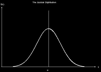
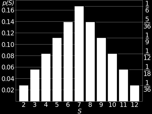
15 Some Probability theory
16 Central Limit Theorem
17 Linear Feedback Shift Registers Uniform Pseudo-Random Number Generation... XOR/XNOR of some bits (taps) of previous state is input bit of the shift register. Length of Random cycle dependent on taps. One with maximum cycle can be considered to fairly uniformly random. List of taps for given length: ation_notes/xapp052.pdf X
18 Note The approach mentioned above is one of the many possible solutions to the problem statement. You should search more and come up with a better solution.
19 Anderson-Darling Test
20 Extra Task Only if you complete the compulsory task Write an encoder and decoder for LDPC codes. Add the GRN (Noise) to output of encoder and pass it as input to decoder. Do it for large number samples, and get number of errors. Repeat for different values of SNR and plot the BER curve for the system.
21 Questions?
FPGA Design Challenge :Techkriti 14 Digital Design using Verilog Part 2
 FPGA Design Challenge :Techkriti 14 Digital Design using Verilog Part 2 Anurag Dwivedi Recap Verilog- Hardware Description Language Modules Combinational circuits assign statement Control statements Sequential
Digital Design with FPGAs. By Neeraj Kulkarni
 Digital Design with FPGAs By Neeraj Kulkarni Some Basic Electronics Basic Elements: Gates: And, Or, Nor, Nand, Xor.. Memory elements: Flip Flops, Registers.. Techniques to design a circuit using basic
FPGA Design Challenge :Techkriti 14 Digital Design using Verilog Part 1
 FPGA Design Challenge :Techkriti 14 Digital Design using Verilog Part 1 Anurag Dwivedi Digital Design : Bottom Up Approach Basic Block - Gates Digital Design : Bottom Up Approach Gates -> Flip Flops Digital
Nikhil Gupta. FPGA Challenge Takneek 2012
 Nikhil Gupta FPGA Challenge Takneek 2012 RECAP FPGA Field Programmable Gate Array Matrix of logic gates Can be configured in any way by the user Codes for FPGA are executed in parallel Configured using
Verilog Fundamentals. Shubham Singh. Junior Undergrad. Electrical Engineering
 Verilog Fundamentals Shubham Singh Junior Undergrad. Electrical Engineering VERILOG FUNDAMENTALS HDLs HISTORY HOW FPGA & VERILOG ARE RELATED CODING IN VERILOG HDLs HISTORY HDL HARDWARE DESCRIPTION LANGUAGE
Hardware Description Languages (HDLs) Verilog
 Verilog") Hardware Description Languages (HDLs) Verilog Material from Mano & Ciletti book By Kurtulus KULLU Ankara University What are HDLs? A Hardware Description Language resembles a programming language specifically
Hardware Description Languages (HDLs) Verilog Material from Mano & Ciletti book By Kurtulus KULLU Ankara University What are HDLs? A Hardware Description Language resembles a programming language specifically
Module 2.1 Gate-Level/Structural Modeling. UNIT 2: Modeling in Verilog
 Module 2.1 Gate-Level/Structural Modeling UNIT 2: Modeling in Verilog Module in Verilog A module definition always begins with the keyword module. The module name, port list, port declarations, and optional
Digital Logic Design using Verilog and FPGA devices Part 2. An Introductory Lecture Series By Chirag Sangani
 Digital Logic Design using Verilog and FPGA devices Part 2 An Introductory Lecture Series By A Small Recap Verilog allows us to design circuits, FPGAs allow us to test these circuits in real-time. The
Chap 6 Introduction to HDL (d)
") Design with Verilog Chap 6 Introduction to HDL (d) Credit to: MD Rizal Othman Faculty of Electrical & Electronics Engineering Universiti Malaysia Pahang Ext: 6036 VERILOG HDL Basic Unit A module Module
Design with Verilog Chap 6 Introduction to HDL (d) Credit to: MD Rizal Othman Faculty of Electrical & Electronics Engineering Universiti Malaysia Pahang Ext: 6036 VERILOG HDL Basic Unit A module Module
Federal Urdu University of Arts, Science and Technology, Islamabad VLSI SYSTEM DESIGN. Prepared By: Engr. Yousaf Hameed.
 VLSI SYSTEM DESIGN Prepared By: Engr. Yousaf Hameed Lab Engineer BASIC ELECTRICAL & DIGITAL SYSTEMS LAB DEPARTMENT OF ELECTRICAL ENGINEERING VLSI System Design 1 LAB 01 Schematic Introduction to DSCH and
A Brief Introduction to Verilog Hardware Definition Language (HDL)
") www.realdigital.org A Brief Introduction to Verilog Hardware Definition Language (HDL) Forward Verilog is a Hardware Description language (HDL) that is used to define the structure and/or behavior of digital
www.realdigital.org A Brief Introduction to Verilog Hardware Definition Language (HDL) Forward Verilog is a Hardware Description language (HDL) that is used to define the structure and/or behavior of digital
Introduction to Verilog
 Introduction to Verilog COE 202 Digital Logic Design Dr. Muhamed Mudawar King Fahd University of Petroleum and Minerals Presentation Outline Hardware Description Language Logic Simulation versus Synthesis
Module 4. Design of Embedded Processors. Version 2 EE IIT, Kharagpur 1
 Module 4 Design of Embedded Processors Version 2 EE IIT, Kharagpur 1 Lesson 22 Introduction to Hardware Description Languages - II Version 2 EE IIT, Kharagpur 2 Instructional Objectives At the of the lesson
ECE 353 Lab 4. Verilog Review. Professor Daniel Holcomb With material by Professor Moritz and Kundu UMass Amherst Fall 2016
 ECE 353 Lab 4 Verilog Review Professor Daniel Holcomb With material by Professor Moritz and Kundu UMass Amherst Fall 2016 Recall What You Will Do Design and implement a serial MIDI receiver Hardware in
DIGITAL SYSTEM DESIGN
 DIGITAL SYSTEM DESIGN Prepared By: Engr. Yousaf Hameed Lab Engineer BASIC ELECTRICAL & DIGITAL SYSTEMS LAB DEPARTMENT OF ELECTRICAL ENGINEERING Digital System Design 1 Name: Registration No: Roll No: Semester:
Chap 3. Modeling structure & basic concept of Verilog HDL
 Chap 3. Modeling structure & basic concept of Verilog HDL Fall semester, 2016 Prof. Jaeseok Kim School of Electrical & Electronics Eng. Yonsei university jaekim@yonsei.ac.kr Digital System Design 3-1 Chapter
DIGITAL SYSTEM DESIGN
 DIGITAL SYSTEM DESIGN Prepared By: Engr. Yousaf Hameed Lab Engineer BASIC ELECTRICAL & DIGITAL SYSTEMS LAB DEPARTMENT OF ELECTRICAL ENGINEERING Digital System Design 1 Name: Registration No: Roll No: Semester:
Writing Circuit Descriptions 8
 8 Writing Circuit Descriptions 8 You can write many logically equivalent descriptions in Verilog to describe a circuit design. However, some descriptions are more efficient than others in terms of the
FPGA: FIELD PROGRAMMABLE GATE ARRAY Verilog: a hardware description language. Reference: [1]
![FPGA: FIELD PROGRAMMABLE GATE ARRAY Verilog: a hardware description language. Reference: [1]](/thumbs/80/81661285.jpg "FPGA: FIELD PROGRAMMABLE GATE ARRAY Verilog: a hardware description language. Reference: [1]") FPGA: FIELD PROGRAMMABLE GATE ARRAY Verilog: a hardware description language Reference: [] FIELD PROGRAMMABLE GATE ARRAY FPGA is a hardware logic device that is programmable Logic functions may be programmed
FPGA: FIELD PROGRAMMABLE GATE ARRAY Verilog: a hardware description language Reference: [] FIELD PROGRAMMABLE GATE ARRAY FPGA is a hardware logic device that is programmable Logic functions may be programmed
a, b sum module add32 sum vector bus sum[31:0] sum[0] sum[31]. sum[7:0] sum sum overflow module add32_carry assign
![a, b sum module add32 sum vector bus sum[31:0] sum[0] sum[31]. sum[7:0] sum sum overflow module add32_carry assign](/thumbs/91/106466219.jpg "a, b sum module add32 sum vector bus sum[31:0] sum[0] sum[31]. sum[7:0] sum sum overflow module add32_carry assign") I hope you have completed Part 1 of the Experiment. This lecture leads you to Part 2 of the experiment and hopefully helps you with your progress to Part 2. It covers a number of topics: 1. How do we specify
I hope you have completed Part 1 of the Experiment. This lecture leads you to Part 2 of the experiment and hopefully helps you with your progress to Part 2. It covers a number of topics: 1. How do we specify
Hardware Description Language VHDL (1) Introduction
 Introduction") Hardware Description Language VHDL (1) Introduction Digital Radiation Measurement and Spectroscopy NE/RHP 537 Introduction Hardware description language (HDL) Intended to describe circuits textually, for
Hardware Description Language VHDL (1) Introduction Digital Radiation Measurement and Spectroscopy NE/RHP 537 Introduction Hardware description language (HDL) Intended to describe circuits textually, for
ECE 353 Lab 3 (Verilog Design Approach)
") ECE 353 Lab 3 (Verilog Design Approach) Prof Daniel Holcomb Recall What You Will Do Design and implement a serial MIDI receiver Hardware in an Altera Complex Programmable Logic Device (CPLD) MAX 7000S
ECE 353 Lab 3 (Verilog Design Approach) Prof Daniel Holcomb Recall What You Will Do Design and implement a serial MIDI receiver Hardware in an Altera Complex Programmable Logic Device (CPLD) MAX 7000S
HDL for Combinational Circuits. ENEL211 Digital Technology
 HDL for Combinational Circuits ENEL211 Digital Technology Lecture Outline Vectors Modular design Tri-state gates Dataflow modelling Behavioural Modelling Vectors Often we want multi-bit quantities in digital
The Verilog Language COMS W Prof. Stephen A. Edwards Fall 2002 Columbia University Department of Computer Science
 The Verilog Language COMS W4995-02 Prof. Stephen A. Edwards Fall 2002 Columbia University Department of Computer Science The Verilog Language Originally a modeling language for a very efficient event-driven
MASSACHUSETTS INSTITUTE OF TECHNOLOGY Department of Electrical Engineering and Computer Sciences
 MASSACHUSETTS INSTITUTE OF TECHNOLOGY Department of Electrical Engineering and Computer Sciences Introductory Digital Systems Lab (6.111) uiz - Spring 2004 Prof. Anantha Chandrakasan Student Name: Problem
Digital Circuit Design and Language. Datapath Design. Chang, Ik Joon Kyunghee University
 Digital Circuit Design and Language Datapath Design Chang, Ik Joon Kyunghee University Typical Synchronous Design + Control Section : Finite State Machine + Data Section: Adder, Multiplier, Shift Register
Spiral 1 / Unit 4 Verilog HDL. Digital Circuit Design Steps. Digital Circuit Design OVERVIEW. Mark Redekopp. Description. Verification.
 1-4.1 1-4.2 Spiral 1 / Unit 4 Verilog HDL Mark Redekopp OVERVIEW 1-4.3 1-4.4 Digital Circuit Design Steps Digital Circuit Design Description Design and computer-entry of circuit Verification Input Stimulus
Combinational Logic Design with Verilog. ECE 152A Winter 2012
 Combinational Logic Design with Verilog ECE 152A Winter 2012 Reading Assignment Brown and Vranesic 2 Introduction to Logic Circuits 2.10 Introduction to Verilog 2.10.1 Structural Specification of Logic
register:a group of binary cells suitable for holding binary information flip-flops + gates
 9 차시 1 Ch. 6 Registers and Counters 6.1 Registers register:a group of binary cells suitable for holding binary information flip-flops + gates control when and how new information is transferred into the
Debouncing a Switch. A Design Example. Page 1
 Debouncing a Switch A Design Example Page 1 Background and Motivation Page 2 When you throw a switch (button or two-pole switch) It often bounces Page 3 Another switch switch after inversion Page 4 Yet
A Verilog Primer. An Overview of Verilog for Digital Design and Simulation
 A Verilog Primer An Overview of Verilog for Digital Design and Simulation John Wright Vighnesh Iyer Department of Electrical Engineering and Computer Sciences College of Engineering, University of California,
Abi Farsoni, Department of Nuclear Engineering and Radiation Health Physics, Oregon State University
 Hardware description language (HDL) Intended to describe circuits textually, for a computer to read Evolved starting in the 1970s and 1980s Popular languages today include: VHDL Defined in 1980s by U.S.
Tutorial 3. Appendix D. D.1 Design Using Verilog Code. The Ripple-Carry Adder Code. Functional Simulation
 Appendix D Tutorial 3 This tutorial introduces more advanced capabilities of the Quartus II system. We show how Verilog code is organized and compiled and illustrate how multibit signals are represented
Introduction to Verilog
 Introduction to Verilog Structure of a Verilog Program A Verilog program is structured as a set of modules, which may represent anything from a collection of logic gates to a complete system. A module
ENEE245 Digital Circuits and Systems Lab Manual
 ENEE245 Digital Circuits and Systems Lab Manual Department of Engineering, Physical & Computer Sciences Montgomery College Modified Fall 2017 Copyright Prof. Lan Xiang (Do not distribute without permission)
Synthesis of Combinational and Sequential Circuits with Verilog
 Synthesis of Combinational and Sequential Circuits with Verilog What is Verilog? Hardware description language: Are used to describe digital system in text form Used for modeling, simulation, design Two
Verilog 1 - Fundamentals
 Verilog 1 - Fundamentals FA FA FA FA module adder( input [3:0] A, B, output cout, output [3:0] S ); wire c0, c1, c2; FA fa0( A[0], B[0], 1 b0, c0, S[0] ); FA fa1( A[1], B[1], c0, c1, S[1] ); FA fa2( A[2],
Chapter 2a: Structural Modeling
 Chapter 2a: Structural Modeling Prof. Ming-Bo Lin Department of Electronic Engineering National Taiwan University of Science and Technology Digital System Designs and Practices Using Verilog HDL and FPGAs
Digital System Design Verilog-Part III. Amir Masoud Gharehbaghi
 Digital System Design Verilog-Part III Amir Masoud Gharehbaghi amgh@mehr.sharif.edu Procedural Blocks initial block always block Place in module body Run concurrently with other module constructs Continuous
ECE 574: Modeling and Synthesis of Digital Systems using Verilog and VHDL. Fall 2017 Final Exam (6.00 to 8.30pm) Verilog SOLUTIONS
 Verilog SOLUTIONS") ECE 574: Modeling and Synthesis of Digital Systems using Verilog and VHDL Fall 2017 Final Exam (6.00 to 8.30pm) Verilog SOLUTIONS Note: Closed book no notes or other material allowed apart from the one
ECE 574: Modeling and Synthesis of Digital Systems using Verilog and VHDL Fall 2017 Final Exam (6.00 to 8.30pm) Verilog SOLUTIONS Note: Closed book no notes or other material allowed apart from the one
What is Verilog HDL? Lecture 1: Verilog HDL Introduction. Basic Design Methodology. What is VHDL? Requirements
 What is Verilog HDL? Lecture 1: Verilog HDL Introduction Verilog Hardware Description Language(HDL)? A high-level computer language can model, represent and simulate digital design Hardware concurrency
ENEE 245 Lab 1 Report Rubrics
 ENEE 4 Lab 1 Report Rubrics Design Clearly state the design requirements Derive the minimum SOP Show the circuit implementation. Draw logic diagram and wiring diagram neatly Label all the diagrams/tables
EE 8351 Digital Logic Circuits Ms.J.Jayaudhaya, ASP/EEE
 EE 8351 Digital Logic Circuits Ms.J.Jayaudhaya, ASP/EEE 1 Logic circuits for digital systems may be combinational or sequential. A combinational circuit consists of input variables, logic gates, and output
Speaker: Shao-Wei Feng Adviser: Prof. An-Yeu Wu Date: 2010/09/28
 99-1 Under-Graduate Project Verilog Simulation & Debugging Tools Speaker: Shao-Wei Feng Adviser: Prof. An-Yeu Wu Date: 2010/09/28 ACCESS IC LAB Outline Basic Concept of Verilog HDL Gate Level Modeling
Chapter 2 Using Hardware Description Language Verilog. Overview
 Chapter 2 Using Hardware Description Language Verilog CSE4210 Winter 2012 Mokhtar Aboelaze based on slides by Dr. Shoab A. Khan Overview Algorithm development isa usually done in MATLAB, C, or C++ Code
Chapter 9: Sequential Logic Modules
 Chapter 9: Sequential Logic Modules Prof. Ming-Bo Lin Department of Electronic Engineering National Taiwan University of Science and Technology Digital System Designs and Practices Using Verilog HDL and
Numbering Systems. Number Representations Part 1
 Introduction Verilog HDL modeling language allows numbers being represented in several radix systems. The underlying circuit processes the number in binary, however, input into and output from such circuits
CSE140L: Components and Design Techniques for Digital Systems Lab. Verilog HDL. Instructor: Mohsen Imani UC San Diego. Source: Eric Crabill, Xilinx
 CSE140L: Components and Design Techniques for Digital Systems Lab Verilog HDL Instructor: Mohsen Imani UC San Diego Source: Eric Crabill, Xilinx 1 Hardware description languages Used to describe & model
P-1/26. Samir Palnitkar. Prentice-Hall, Inc. INSTRUCTOR : CHING-LUNG SU.
 : P-1/26 Textbook: Verilog HDL 2 nd. Edition Samir Palnitkar Prentice-Hall, Inc. : INSTRUCTOR : CHING-LUNG SU E-mail: kevinsu@yuntech.edu.tw Chapter 4 P-2/26 Chapter 4 Modules and Outline of Chapter 4
Design Using Verilog
 EGC220 Design Using Verilog Baback Izadi Division of Engineering Programs bai@engr.newpaltz.edu Basic Verilog Lexical Convention Lexical convention are close to C++. Comment // to the of the line. /* to
ENEE245 Digital Circuits and Systems Lab Manual
 ENEE245 Digital Circuits and Systems Lab Manual Department of Engineering, Physical & Computer Sciences Montgomery College Version 1.1 Copyright Prof. Lan Xiang (Do not distribute without permission) 1
ENGN1640: Design of Computing Systems Topic 02: Design/Lab Foundations
 ENGN1640: Design of Computing Systems Topic 02: Design/Lab Foundations Professor Sherief Reda http://scale.engin.brown.edu School of Engineering Brown University Spring 2017 1 Topics 1. Programmable logic
EECS150 - Digital Design Lecture 8 - Hardware Description Languages
 EECS150 - Digital Design Lecture 8 - Hardware Description Languages September 19, 2002 John Wawrzynek Fall 2002 EECS150 - Lec08-HDL Page 1 Netlists Design flow What is a HDL? Verilog history examples Outline
Department of Electrical and Computer Engineering Xilinx ISIM <Release Version: 14.1i> Simulation Tutorial Using Verilog
 Department of Electrical and Computer Engineering Xilinx ISIM Simulation Tutorial Using Verilog Spring 2013 Baback Izadi You will next test the full adder circuit that you built
EN2911X: Reconfigurable Computing Topic 02: Hardware Definition Languages
 EN2911X: Reconfigurable Computing Topic 02: Hardware Definition Languages Professor Sherief Reda http://scale.engin.brown.edu School of Engineering Brown University Spring 2014 1 Introduction to Verilog
Synthesizable Verilog
 Synthesizable Verilog Courtesy of Dr. Edwards@Columbia, and Dr. Franzon@NCSU http://csce.uark.edu +1 (479) 575-6043 yrpeng@uark.edu Design Methodology Structure and Function (Behavior) of a Design HDL
Module 4. Design of Embedded Processors. Version 2 EE IIT, Kharagpur 1
 Module 4 Design of Embedded Processors Version 2 EE IIT, Kharagpur 1 Lesson 23 Introduction to Hardware Description Languages-III Version 2 EE IIT, Kharagpur 2 Instructional Objectives At the end of the
ECE 353 Lab 4. Verilog Review. Professor Daniel Holcomb UMass Amherst Fall 2017
 ECE 353 Lab 4 Verilog Review Professor Daniel Holcomb UMass Amherst Fall 2017 What You Will Do In Lab 4 Design and implement a serial MIDI receiver Hardware in an Altera Complex Programmable Logic Device
Modeling Sequential Circuits in Verilog
 Modeling Sequential Circuits in Verilog COE 202 Digital Logic Design Dr. Muhamed Mudawar King Fahd University of Petroleum and Minerals Presentation Outline Modeling Latches and Flip-Flops Blocking versus
ECE 4514 Digital Design II. Spring Lecture 3: Verilog Bread and Butter
 ECE 4514 Digital Design II Spring 2007 Verilog Difference between synthesis and simulation Modules, module declarations and instantiation Constants Numbers Data types Value Levels Regs Vectors Arrays Synthesis
CS6710 Tool Suite. Verilog is the Key Tool
 CS6710 Tool Suite Verilog-XL Behavioral Verilog Your Library Cadence SOC Encounter Synopsys Synthesis Structural Verilog Circuit Layout CSI Verilog-XL AutoRouter Cadence Virtuoso Layout LVS Layout-XL Cadence
ENGN1640: Design of Computing Systems Topic 02: Design/Lab Foundations
 ENGN1640: Design of Computing Systems Topic 02: Design/Lab Foundations Professor Sherief Reda http://scale.engin.brown.edu School of Engineering Brown University Spring 2016 1 Topics 1. Programmable logic
Verilog Sequential Logic. Verilog for Synthesis Rev C (module 3 and 4)
") Verilog Sequential Logic Verilog for Synthesis Rev C (module 3 and 4) Jim Duckworth, WPI 1 Sequential Logic Module 3 Latches and Flip-Flops Implemented by using signals in always statements with edge-triggered
Verilog Sequential Logic Verilog for Synthesis Rev C (module 3 and 4) Jim Duckworth, WPI 1 Sequential Logic Module 3 Latches and Flip-Flops Implemented by using signals in always statements with edge-triggered
Computer Aided Design Basic Syntax Gate Level Modeling Behavioral Modeling. Verilog
 Verilog Radek Pelánek and Šimon Řeřucha Contents 1 Computer Aided Design 2 Basic Syntax 3 Gate Level Modeling 4 Behavioral Modeling Computer Aided Design Hardware Description Languages (HDL) Verilog C
C-Based Hardware Design
 LECTURE 6 In this lecture we will introduce: The VHDL Language and its benefits. The VHDL entity Concurrent and Sequential constructs Structural design. Hierarchy Packages Various architectures Examples
This Lecture. Some components (useful for the homework) Verilog HDL (will continue next lecture)
 Verilog HDL (will continue next lecture)") Last Lecture The basic component of a digital circuit is the MOS transistor Transistor have instrinsic resistance and capacitance, so voltage values in the circuit take some time to change ( delay ) There
Last Lecture The basic component of a digital circuit is the MOS transistor Transistor have instrinsic resistance and capacitance, so voltage values in the circuit take some time to change ( delay ) There
Course Topics - Outline
 Course Topics - Outline Lecture 1 - Introduction Lecture 2 - Lexical conventions Lecture 3 - Data types Lecture 4 - Operators Lecture 5 - Behavioral modeling A Lecture 6 Behavioral modeling B Lecture 7
Hardware Design Environments. Dr. Mahdi Abbasi Computer Engineering Department Bu-Ali Sina University
 Hardware Design Environments Dr. Mahdi Abbasi Computer Engineering Department Bu-Ali Sina University Outline Welcome to COE 405 Digital System Design Design Domains and Levels of Abstractions Synthesis
Complex Combinational circuits in Bluespec
 Complex Combinational circuits in Bluespec Arvind Computer Science & Artificial Intelligence Lab M.I.T. L05-1 2-bit Ripple-Carry Adder cascading full adders x[1] y[1] x[0] y[0] c[2] fa c[1] fa 0 Use fa
Announcements. Midterm 2 next Thursday, 6-7:30pm, 277 Cory Review session on Tuesday, 6-7:30pm, 277 Cory Homework 8 due next Tuesday Labs: project
 - Fall 2002 Lecture 20 Synthesis Sequential Logic Announcements Midterm 2 next Thursday, 6-7:30pm, 277 Cory Review session on Tuesday, 6-7:30pm, 277 Cory Homework 8 due next Tuesday Labs: project» Teams
EPC6055 Digital Integrated Circuits EXAM 1 Fall Semester 2013
 EPC6055 Digital Integrated Circuits EXAM 1 Fall Semester 2013 Print Here Student ID Signature This is a closed book exam. The exam is to be completed in one-hundred ten (110) minutes. Don t use scratch
ECE 2300 Digital Logic & Computer Organization. More Sequential Logic Verilog
 ECE 2300 Digital Logic & Computer Organization Spring 2018 More Sequential Logic Verilog Lecture 7: 1 Announcements HW3 will be posted tonight Prelim 1 Thursday March 1, in class Coverage: Lectures 1~7
N-input EX-NOR gate. N-output inverter. N-input NOR gate
 Hardware Description Language HDL Introduction HDL is a hardware description language used to design and document electronic systems. HDL allows designers to design at various levels of abstraction. It
CS429: Computer Organization and Architecture
 CS429: Computer Organization and Architecture Dr. Bill Young Department of Computer Sciences University of Texas at Austin Last updated: January 2, 2018 at 11:23 CS429 Slideset 5: 1 Topics of this Slideset
Topics. Midterm Finish Chapter 7
 Lecture 9 Topics Midterm Finish Chapter 7 Xilinx FPGAs Chapter 7 Spartan 3E Architecture Source: Spartan-3E FPGA Family Datasheet CLB Configurable Logic Blocks Each CLB contains four slices Each slice
Department of Computer Science & Engineering. Lab Manual DIGITAL LAB. Class: 2nd yr, 3rd sem SYLLABUS
 Department of Computer Science & Engineering Lab Manual 435 DIGITAL LAB Class: 2nd yr, 3rd sem SYLLABUS. Verification of Boolean theorems using digital logic gates. 2. Design and implementation of code
CSE140L: Components and Design Techniques for Digital Systems Lab
 CSE140L: Components and Design Techniques for Digital Systems Lab Tajana Simunic Rosing Source: Vahid, Katz, Culler 1 Announcements & Outline Lab 4 due; demo signup times listed on the cse140l site Check
Tutorial on Verilog HDL
 Tutorial on Verilog HDL HDL Hardware Description Languages Widely used in logic design Verilog and VHDL Describe hardware using code Document logic functions Simulate logic before building Synthesize code
ANADOLU UNIVERSITY DEPARTMENT OF ELECTRICAL AND ELECTRONICS ENGINEERING. EEM Digital Systems II
 ANADOLU UNIVERSITY DEPARTMENT OF ELECTRICAL AND ELECTRONICS ENGINEERING EEM 334 - Digital Systems II LAB 1 - INTRODUCTION TO XILINX ISE SOFTWARE AND FPGA 1. PURPOSE In this lab, after you learn to use
Finite-State Machine (FSM) Design
 Design") 1 Finite-State Machine (FSM) Design FSMs, an important category of sequential circuits, are used frequently in designing digital systems. From the daily used electronic machines to the complex digital
1 Finite-State Machine (FSM) Design FSMs, an important category of sequential circuits, are used frequently in designing digital systems. From the daily used electronic machines to the complex digital
Chapter 9: Sequential Logic Modules
 Chapter 9: Sequential Logic Modules Prof. Soo-Ik Chae Digital System Designs and Practices Using Verilog HDL and FPGAs @ 2008, John Wiley 9-1 Objectives After completing this chapter, you will be able
 UNIT II - COMBINATIONAL LOGIC Part A 2 Marks. 1. Define Combinational circuit A combinational circuit consist of logic gates whose outputs at anytime are determined directly from the present combination
CSE140L: Components and Design
 CSE140L: Components and Design Techniques for Digital Systems Lab Tajana Simunic Rosing Source: Vahid, Katz, Culler 1 Grade distribution: 70% Labs 35% Lab 4 30% Lab 3 20% Lab 2 15% Lab 1 30% Final exam
M A S S A C H U S E T T S I N S T I T U T E O F T E C H N O L O G Y DEPARTMENT OF ELECTRICAL ENGINEERING AND COMPUTER SCIENCE
 M A S S A C H U S E T T S I N S T I T U T E O F T E C H N O L O G Y DEPARTMENT OF ELECTRICAL ENGINEERING AND COMPUTER SCIENCE 6.111 Introductory Digital Systems Laboratory Fall 2017 Lecture PSet #6 of
Verilog for High Performance
 Verilog for High Performance Course Description This course provides all necessary theoretical and practical know-how to write synthesizable HDL code through Verilog standard language. The course goes
Digital Integrated Circuits
 Digital Integrated Circuits Lecture 4 Jaeyong Chung System-on-Chips (SoC) Laboratory Incheon National University BCD TO EXCESS-3 CODE CONVERTER 0100 0101 +0011 +0011 0111 1000 LSB received first Chung
Verilog HDL. Gate-Level Modeling
 Verilog HDL Verilog is a concurrent programming language unlike C, which is sequential in nature. block - executes once at time 0. If there is more then one block, each execute concurrently always block
Course Topics - Outline
 Course Topics - Outline Lecture 1 - Introduction Lecture 2 - Lexical conventions Lecture 3 - Data types Lecture 4 - Operators Lecture 5 - Behavioral modeling A Lecture 6 Behavioral modeling B Lecture 7
תכן חומרה בשפת VERILOG הפקולטה להנדסה
 תכן חומרה בשפת VERILOG סמסטר ב' תשע"ג משה דורון מרצה: מתרגלים: אריאל בורג, חג'ג' חן הפקולטה להנדסה 1 Course Topics - Outline Lecture 1 - Introduction Lecture 2 - Lexical conventions Lecture 3 - Data types
VeriLogger Tutorial: Basic Verilog Simulation
 VeriLogger Tutorial: Basic Verilog Simulation This tutorial demonstrates the basic simulation features of VeriLogger Pro. It teaches you how to create and manage a project and how to build, simulate, and
Combinational Logic II
 Combinational Logic II Ranga Rodrigo July 26, 2009 1 Binary Adder-Subtractor Digital computers perform variety of information processing tasks. Among the functions encountered are the various arithmetic
Veriolog Overview. CS/EE 3710 Fall 2010
 Veriolog Overview CS/EE 3710 Fall 2010 Hardware Description Languages HDL Designed to be an alternative to schematics for describing hardware systems Two main survivors VHDL Commissioned by DOD Based on
EECS150 - Digital Design Lecture 5 - Verilog Logic Synthesis
 EECS150 - Digital Design Lecture 5 - Verilog Logic Synthesis Jan 31, 2012 John Wawrzynek Spring 2012 EECS150 - Lec05-verilog_synth Page 1 Outline Quick review of essentials of state elements Finite State
 PAGE NO: EXP NO: 1A SIMULATION OF HALF ADDER AND FULL ADDER. DATE: AIM: To design, simulate and synthesize the Half adder and Full adder. TOOLS REQUIRED: SOFTWARE: XILINX ISE 9.1i ALGORITHM: 1. Start the
Chapter-5. EE 335 : Advanced Microprocessor. Logic Design with Behavioral Models of Combinational and Sequential Logic
 EE 335 : Advanced Microprocessor Chapter-5 Logic Design with Behavioral Models of Combinational and Sequential Logic Ajay Kumar Yadav (Instructor) Electrical & Computer Engineering Temple University Data
University of Toronto Faculty of Applied Science and Engineering Edward S. Rogers Sr. Department of Electrical and Computer Engineering
 University of Toronto Faculty of Applied Science and Engineering Edward S. Rogers Sr. Department of Electrical and Computer Engineering Final Examination ECE 241F - Digital Systems Examiners: S. Brown,
EECS150 - Digital Design Lecture 4 - Verilog Introduction. Outline
 EECS150 - Digital Design Lecture 4 - Verilog Introduction Feb 3, 2009 John Wawrzynek Spring 2009 EECS150 - Lec05-Verilog Page 1 Outline Background and History of Hardware Description Brief Introduction
Problem Set 3 Solutions
 Problem Set 3 Solutions ECE 551: Digital System Design and Synthesis Fall 2001 Final Version 1) For each of the following always behaviors: a) Does the given always behavior need a default statement as
Lab 2: Barrel Shifter Design
 EGR 400 A Advanced Digital System Design Using FPGAs Lab 2: Barrel Shifter Design Prepared for: Dr. Foist Christopher Parisi College of Engineering California Baptist University 10/05/12 Introduction The
ECEN 468 Advanced Digital System Design
 ECEN 468 Advanced Digital System Design Lecture 19: Logic Design with Verilog Verilog Module v Description of internal structure/function o Implicit semantic of time associated with each data object/ signal