ECE 4514 Digital Design II. Spring Lecture 2: Hierarchical Design
|
|
|
- Kory Banks
- 5 years ago
- Views:
Transcription
1 ECE 4514 Digital Design II Spring 2007
2 Abstraction in Hardware Design Remember from last lecture that HDLs offer a textual description of a netlist. Through abstraction in the HDL, we can capture more than a single transistor or gate at a time. Similar to a function call in C that abstracts a large collection of expressions Similar to a Lego castle that abstracts a large collection of Lego bricks Verilog offers three types of abstraction Structural Dataflow Behavioral These two are related, we call both of them just 'behavioral' for now
3 Structural Modeling Describe a module in terms of components R QB S Q Netlist two modules: NAND_1 and NAND_2 net 1: Rbar to NAND_1, input_1 net 2: Sbar to NAND_2, input_2 net 3: NAND_1, output_1 to NAND_2, input_1 etc..
4 Behavioral Modeling Describe a module in terms of input-output behavior input S, R; output Q, QB; if ( S == 1 ) and (R == 0 ) then Set Q to 1, set QB to 0 else if ( S == 1 ) and (R == 1 ) then Set Q to 1, set QB to 1 else if ( S == 0 ) and (R == 0 ) then *Hold current state* else if ( S == 0 ) and (R == 1 ) then Set Q to 0, set QB to 1
5 Behavioral and Structural are dual mechanisms Rbar Sbar my_flop Q Qbar Structural Description explains what happens to Q and Qbar in terms of a netlist of lower-level components Behavioral Description explains what happens to Q and Qbar in terms of Rbar and Sbar
6 Structural and Behavioral are related A model can be expressed as behavior or structure (of lower-level models) Level 1 Rbar Sbar my_flop Q Qbar Level 2 Rbar Sbar NAND NAND Q Qbar
7 Top-down design my_pc motherboard Start here, rewrite behavior into structure until you reach primitive behavior harddisk controller cpu memory io controller integer unit cache regfile ALU shifter NAND NOR Leaf Cells of Primitive Behavior
8 Bottom-up design my_pc motherboard Equivalent Top-level Behavior harddisk controller cpu memory io controller integer unit cache regfile ALU shifter NAND NOR Start here, compose structure into larger modules until you reach equivalent top-level behavior
9 Bottom-up, Top-down are both useful When re-using modules from one design to the next: bottom-up When developing new modules from scratch: top-down In practice, top-down and bottom-up techniques are combined. In Verilog, a given module can be expressed as structure or else as behavior. There are two flavors of 'behavior' in Verilog Behavioral: similar to a sequential description in C Dataflow: a collection of concurrent expressions
10 Example of a hierarchical model 4-bit counter q0 q1 q2 q3 T-ff T-ff T-ff T-ff q q q q reset Top-level structure contains 4 interconnected T flip-flops
11 T flip-flop, behavior clk T-ff q reset Behavior can be captured in three rules: (1) (2) (3) at each negative clock edge: old_state = new_state any time you see a change on old_state: new_state = not old_state q = old_state any time you see a change on reset: new_state = 0
12 T flip-flop, structure T-ff q reset T-flipflop D D-ff q D-flipflop inverter Thus, we can build a 4-bit counter with inverters and D-flipflops reset
13 D flipflop in Verilog module D_FF(q, d, clk, reset); output q; input d, clk, reset; reg q; reset or negedge clk) if (reset) q <= 1'b0; else q <= d; endmodule
14 D flipflop in Verilog module D_FF(q, d, clk, reset); output q; input d, clk, reset; reg q; one output port, three input ports 'reg' means that q is a variable reset or negedge clk) if (reset) means: whenever q <= 1'b0; (condition) is true, proceed. else q <= d; endmodule The '<=' is called a dataflow assignment, in this case the effect is similar to assigning d to q This is a behavioral description in dataflow format
15 T flipflop in Verilog module T_FF(q, clk, reset); output q; input clk, reset; wire d; D_FF dff0(q, d, clk, reset); not n1(d, q); endmodule
16 T flipflop in Verilog module T_FF(q, clk, reset); output q; input clk, reset; wire d; D_FF dff0(q, d, clk, reset); not n1(d, q); endmodule connect corresponding terminals of module module D_FF(q, d, clk, reset);
17 T flipflop in Verilog module T_FF(q, clk, reset); output q; input clk, reset; wire d; one output port, two input ports a wire d has no storage: its value is always determined in terms of other variables D_FF dff0(q, d, clk, reset); not n1(d, q); endmodule 'not' is a primitive in Verilog: the simulator understands what this module does. This is a structural description
18 4-bit counter in Verilog module ripple_carry_counter(q, clk, reset); output [3:0] q; input clk, reset; T_FF tff0(q[0], clk, reset); T_FF tff1(q[1], q[0], reset); T_FF tff2(q[2], q[1], reset); T_FF tff3(q[3], q[2], reset); endmodule
19 4-bit counter in Verilog module ripple_carry_counter(q, clk, reset); output [3:0] q; four output ports, two input ports input clk, reset; T_FF tff0(q[0], clk, reset); T_FF tff1(q[1], q[0], reset); T_FF tff2(q[2], q[1], reset); T_FF tff3(q[3], q[2], reset); endmodule This is a structural description
20 Simulation In order to test the 4-bit counter, we need a clock signal and a reset signal. We also need to monitor the counter's output. These activities can be implemented in a testbench. ripple_carry_counter some behavioral code clk reset q[0:3] clk reset q[0:3]
21 Testbench module stimulus; reg clk; reg reset; wire [3:0] q; ripple_carry_counter(q, clk,reset); initial clk = 1'b0; always #5 clk = ~clk; initial begin reset = 1'b1; #15 reset = 1'b0; #180 reset = 1'b1; #10 reset = 1'b0; #20 $finish; end initial $monitor($time, " Output q = %d", q); endmodule
22 Testbench module stimulus; reg clk; reg reset; wire [3:0] q; ripple_carry_counter(q, clk,reset); initial clk = 1'b0; always #5 clk = ~clk; when simulation starts, clk is low each 5 time units, clk will flip value initial begin reset = 1'b1; #15 reset = 1'b0; #180 reset = 1'b1; #10 reset = 1'b0; #20 $finish; end when simulation starts, reset is high. after 15 time units, reset is low. after 180 time units, reset is high. after 10 time units, reset is low. after 20 time units, stop simulation. initial $monitor($time, " Output q = %d", q); endmodule each time q changes, print its value
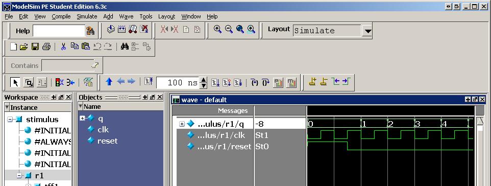
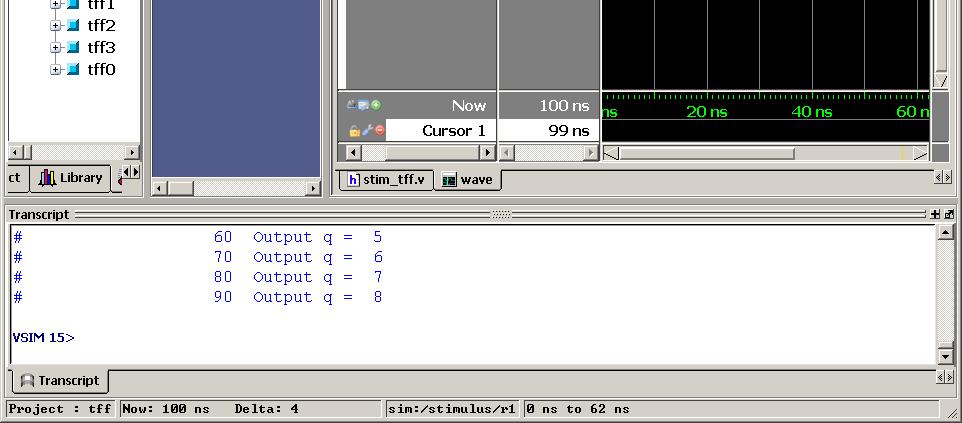
23 Modelsim
24 Summary Behavioral and Structural Modeling are two complementary forms for Hardware Description They are linked with top-down (behavior into structure) or bottom-up (structure into behavior) design 4-bit counter as an example of bottom-up design Check design files on Blackboard
P-1/26. Samir Palnitkar. Prentice-Hall, Inc. INSTRUCTOR : CHING-LUNG SU.
 : P-1/26 Textbook: Verilog HDL 2 nd. Edition Samir Palnitkar Prentice-Hall, Inc. : INSTRUCTOR : CHING-LUNG SU E-mail: kevinsu@yuntech.edu.tw Chapter 4 P-2/26 Chapter 4 Modules and Outline of Chapter 4
Verilog HDL. Lecture #6. Madhu Mutyam Dept. of Computer Science and Engineering Indian Institute of Technology, Madras
 Verilog HDL Lecture #6 Madhu Mutyam Dept. of Computer Science and Engineering Indian Institute of Technology, Madras madhu@cse.iitm.ac.in 2 Verilog RTL Structural Level Verilog allows a designer to develop
Logic Circuits II ECE 2411 Thursday 4:45pm-7:20pm. Lecture 3
 Logic Circuits II ECE 2411 Thursday 4:45pm-7:20pm Lecture 3 Lecture 3 Topics Covered: Chapter 4 Discuss Sequential logic Verilog Coding Introduce Sequential coding Further review of Combinational Verilog
Verilog HDL. Gate-Level Modeling
 Verilog HDL Verilog is a concurrent programming language unlike C, which is sequential in nature. block - executes once at time 0. If there is more then one block, each execute concurrently always block
VERILOG. Deepjyoti Borah, Diwahar Jawahar
 VERILOG Deepjyoti Borah, Diwahar Jawahar Outline 1. Motivation 2. Basic Syntax 3. Sequential and Parallel Blocks 4. Conditions and Loops in Verilog 5. Procedural Assignment 6. Timing controls 7. Combinatorial
Blocking(=) vs Nonblocking (<=) Assignment. Lecture 3: Modeling Sequential Logic in Verilog HDL. Procedural assignments
 vs Nonblocking (<=) Assignment. Lecture 3: Modeling Sequential Logic in Verilog HDL. Procedural assignments") Blocking(=) vs Nonblocking (
Blocking(=) vs Nonblocking (
Chap 3. Modeling structure & basic concept of Verilog HDL
 Chap 3. Modeling structure & basic concept of Verilog HDL Fall semester, 2016 Prof. Jaeseok Kim School of Electrical & Electronics Eng. Yonsei university jaekim@yonsei.ac.kr Digital System Design 3-1 Chapter
Digital System Design Verilog-Part III. Amir Masoud Gharehbaghi
 Digital System Design Verilog-Part III Amir Masoud Gharehbaghi amgh@mehr.sharif.edu Procedural Blocks initial block always block Place in module body Run concurrently with other module constructs Continuous
ARM 64-bit Register File
 ARM 64-bit Register File Introduction: In this class we will develop and simulate a simple, pipelined ARM microprocessor. Labs #1 & #2 build some basic components of the processor, then labs #3 and #4
ECE 4514 Digital Design II. Spring Lecture 9: Review of Key Ideas, System Commands and Testbenches
 ECE 4514 Digital Design II Lecture 9: Review of Key Ideas, System Commands and Testbenches A Language Lecture Iterating the Key Ideas Verilog is a modeling language. It cannot express hardware directly.
ECE 2300 Digital Logic & Computer Organization. More Sequential Logic Verilog
 ECE 2300 Digital Logic & Computer Organization Spring 2018 More Sequential Logic Verilog Lecture 7: 1 Announcements HW3 will be posted tonight Prelim 1 Thursday March 1, in class Coverage: Lectures 1~7
Verilog HDL [As per Choice Based Credit System (CBCS) scheme]
![Verilog HDL [As per Choice Based Credit System (CBCS) scheme]](/thumbs/89/100794459.jpg "Verilog HDL [As per Choice Based Credit System (CBCS) scheme]") Verilog HDL [As per Choice Based Credit System (CBCS) scheme] Subject Code IA Marks 20 Number of Lecture 04 Exam Marks 80 Hours/Week Total Number of 50 (10 Hours / Module) Exam Hours 03 Lecture Hours CREDITS
Verilog HDL [As per Choice Based Credit System (CBCS) scheme] Subject Code IA Marks 20 Number of Lecture 04 Exam Marks 80 Hours/Week Total Number of 50 (10 Hours / Module) Exam Hours 03 Lecture Hours CREDITS
Synthesizable Verilog
 Synthesizable Verilog Courtesy of Dr. Edwards@Columbia, and Dr. Franzon@NCSU http://csce.uark.edu +1 (479) 575-6043 yrpeng@uark.edu Design Methodology Structure and Function (Behavior) of a Design HDL
Date Performed: Marks Obtained: /10. Group Members (ID):. Experiment # 11. Introduction to Verilog II Sequential Circuits
:. Experiment # 11. Introduction to Verilog II Sequential Circuits") Name: Instructor: Engr. Date Performed: Marks Obtained: /10 Group Members (ID):. Checked By: Date: Experiment # 11 Introduction to Verilog II Sequential Circuits OBJECTIVES: To understand the concepts
Name: Instructor: Engr. Date Performed: Marks Obtained: /10 Group Members (ID):. Checked By: Date: Experiment # 11 Introduction to Verilog II Sequential Circuits OBJECTIVES: To understand the concepts
ECE 4514 Digital Design II. Spring Lecture 13: Logic Synthesis
 ECE 4514 Digital Design II A Tools/Methods Lecture Second half of Digital Design II 9 10-Mar-08 L13 (T) Logic Synthesis PJ2 13-Mar-08 L14 (D) FPGA Technology 10 18-Mar-08 No Class (Instructor on Conference)
Sequential Logic Blocks
 Sequential Logic Blocks Output of sequential blocks depends on present state as well as on past state. Sequential circuits work with a reference which is clock. A clock signal can be of any duty cycle,
register:a group of binary cells suitable for holding binary information flip-flops + gates
 9 차시 1 Ch. 6 Registers and Counters 6.1 Registers register:a group of binary cells suitable for holding binary information flip-flops + gates control when and how new information is transferred into the
Post-Synthesis Simulation. VITAL Models, SDF Files, Timing Simulation
 Post-Synthesis Simulation VITAL Models, SDF Files, Timing Simulation Post-synthesis simulation Purpose: Verify correctness of synthesized circuit Verify synthesis tool delay/timing estimates Synthesis
EN164: Design of Computing Systems Lecture 06: Lab Foundations / Verilog 2
 EN164: Design of Computing Systems Lecture 06: Lab Foundations / Verilog 2 Professor Sherief Reda http://scaleenginbrownedu Electrical Sciences and Computer Engineering School of Engineering Brown University
ENGN1640: Design of Computing Systems Topic 02: Design/Lab Foundations
 ENGN1640: Design of Computing Systems Topic 02: Design/Lab Foundations Professor Sherief Reda http://scale.engin.brown.edu School of Engineering Brown University Spring 2017 1 Topics 1. Programmable logic
Modeling Sequential Circuits in Verilog
 Modeling Sequential Circuits in Verilog COE 202 Digital Logic Design Dr. Muhamed Mudawar King Fahd University of Petroleum and Minerals Presentation Outline Modeling Latches and Flip-Flops Blocking versus
Introduction. Purpose. Intended Audience. Conventions. Close
 Introduction Introduction Verilog-XL is a simulator that allows you to test the logic of a design. The process of logic simulation in Verilog-XL is as follows: 1. Describe the design to Verilog-XL. 2.
N-input EX-NOR gate. N-output inverter. N-input NOR gate
 Hardware Description Language HDL Introduction HDL is a hardware description language used to design and document electronic systems. HDL allows designers to design at various levels of abstraction. It
Don t expect to be able to write and debug your code during the lab session.
 EECS150 Spring 2002 Lab 4 Verilog Simulation Mapping UNIVERSITY OF CALIFORNIA AT BERKELEY COLLEGE OF ENGINEERING DEPARTMENT OF ELECTRICAL ENGINEERING AND COMPUTER SCIENCE Lab 4 Verilog Simulation Mapping
Introduction. Why Use HDL? Simulation output. Explanation
 Introduction Verilog HDL is a Hardware Description Language (HDL) HDL is a language used to describe a digital system, for example, a computer or a component of a computer. Most popular HDLs are VHDL and
ENGN1640: Design of Computing Systems Topic 02: Design/Lab Foundations
 ENGN1640: Design of Computing Systems Topic 02: Design/Lab Foundations Professor Sherief Reda http://scale.engin.brown.edu School of Engineering Brown University Spring 2016 1 Topics 1. Programmable logic
Hardware Description Languages (HDLs) Verilog
 Verilog") Hardware Description Languages (HDLs) Verilog Material from Mano & Ciletti book By Kurtulus KULLU Ankara University What are HDLs? A Hardware Description Language resembles a programming language specifically
Hardware Description Languages (HDLs) Verilog Material from Mano & Ciletti book By Kurtulus KULLU Ankara University What are HDLs? A Hardware Description Language resembles a programming language specifically
Synthesis of Combinational and Sequential Circuits with Verilog
 Synthesis of Combinational and Sequential Circuits with Verilog What is Verilog? Hardware description language: Are used to describe digital system in text form Used for modeling, simulation, design Two
ECE 4514 Digital Design II. Spring Lecture 20: Timing Analysis and Timed Simulation
 ECE 4514 Digital Design II Lecture 20: Timing Analysis and Timed Simulation A Tools/Methods Lecture Topics Static and Dynamic Timing Analysis Static Timing Analysis Delay Model Path Delay False Paths Timing
EN164: Design of Computing Systems Lecture 07: Lab Foundations / Verilog 3
 EN164: Design of Computing Systems Lecture 07: Lab Foundations / Verilog 3 Professor Sherief Reda http://scaleenginbrownedu Electrical Sciences and Computer Engineering School of Engineering Brown University
Lecture 15: System Modeling and Verilog
 Lecture 15: System Modeling and Verilog Slides courtesy of Deming Chen Intro. VLSI System Design Outline Outline Modeling Digital Systems Introduction to Verilog HDL Use of Verilog HDL in Synthesis Reading
Why Should I Learn This Language? VLSI HDL. Verilog-2
 Verilog Why Should I Learn This Language? VLSI HDL Verilog-2 Different Levels of Abstraction Algorithmic the function of the system RTL the data flow the control signals the storage element and clock Gate
yamin/
 http://cis.k.hosei.ac.jp/ yamin/ Verilog HDL p.1/76 HDL Verilog HDL IEEE Standard 1364-1995 (Verilog-1995) IEEE Standard 1364-2001 (Verilog-2001) VHDL VHSIC HDL IEEE Standard 1076-1987 AHDL Altera HDL
What is Verilog HDL? Lecture 1: Verilog HDL Introduction. Basic Design Methodology. What is VHDL? Requirements
 What is Verilog HDL? Lecture 1: Verilog HDL Introduction Verilog Hardware Description Language(HDL)? A high-level computer language can model, represent and simulate digital design Hardware concurrency
CSCB58 - Lab 3. Prelab /3 Part I (in-lab) /2 Part II (in-lab) /2 TOTAL /8
 /2 Part II (in-lab) /2 TOTAL /8") CSCB58 - Lab 3 Latches, Flip-flops, and Registers Learning Objectives The purpose of this exercise is to investigate the fundamental synchronous logic elements: latches, flip-flops, and registers. Prelab
CSCB58 - Lab 3 Latches, Flip-flops, and Registers Learning Objectives The purpose of this exercise is to investigate the fundamental synchronous logic elements: latches, flip-flops, and registers. Prelab
EECS150 - Digital Design Lecture 8 - Hardware Description Languages
 EECS150 - Digital Design Lecture 8 - Hardware Description Languages September 19, 2002 John Wawrzynek Fall 2002 EECS150 - Lec08-HDL Page 1 Netlists Design flow What is a HDL? Verilog history examples Outline
VLSI Design 13. Introduction to Verilog
 Last module: Sequential circuit design Design styles This module Synthesis Brief introduction to Verilog Synthesis in the Design Flow Designer Tasks Tools Architect Logic Designer Circuit Designer Define
Online Verilog Resources
 EECS 427 Discussion 6: Verilog HDL Reading: Many references EECS 427 F08 Discussion 6 1 Online Verilog Resources ASICs the book, Ch. 11: http://www.ge.infn.it/~pratolo/verilog/verilogtutorial.pdf it/ pratolo/verilog/verilogtutorial
Spring 2017 EE 3613: Computer Organization Chapter 5: Processor: Datapath & Control - 2 Verilog Tutorial
 Spring 2017 EE 3613: Computer Organization Chapter 5: Processor: Datapath & Control - 2 Verilog Tutorial Avinash Kodi Department of Electrical Engineering & Computer Science Ohio University, Athens, Ohio
Lab 7 (All Sections) Prelab: Introduction to Verilog
 Prelab: Introduction to Verilog") Lab 7 (All Sections) Prelab: Introduction to Verilog Name: Sign the following statement: On my honor, as an Aggie, I have neither given nor received unauthorized aid on this academic work 1 Objective The
Lab 7 (All Sections) Prelab: Introduction to Verilog Name: Sign the following statement: On my honor, as an Aggie, I have neither given nor received unauthorized aid on this academic work 1 Objective The
Quick Introduction to SystemVerilog: Sequental Logic
 ! Quick Introduction to SystemVerilog: Sequental Logic Lecture L3 8-545 Advanced Digital Design ECE Department Many elements Don Thomas, 24, used with permission with credit to G. Larson Today Quick synopsis
The University of Alabama in Huntsville ECE Department CPE Final Exam April 28, 2016
 The University of Alabama in Huntsville ECE Department CPE 426 01 Final Exam April 28, 2016 Name: 1. (6 points) Draw the transistor-level diagram of a two input CMOS NAND gate. 2. (5 points) If the NRE
EPC6055 Digital Integrated Circuits EXAM 1 Fall Semester 2013
 EPC6055 Digital Integrated Circuits EXAM 1 Fall Semester 2013 Print Here Student ID Signature This is a closed book exam. The exam is to be completed in one-hundred ten (110) minutes. Don t use scratch
RTL Design (Using ASM/SM Chart)
") Digital Circuit Design and Language RTL Design (Using ASM/SM Chart) Chang, Ik Joon Kyunghee University Process of Logic Simulation and Synthesis Design Entry HDL Description Logic Simulation Functional
Digital Circuit Design and Language RTL Design (Using ASM/SM Chart) Chang, Ik Joon Kyunghee University Process of Logic Simulation and Synthesis Design Entry HDL Description Logic Simulation Functional
CAD for VLSI Design - I. Lecture 21 V. Kamakoti and Shankar Balachandran
 CAD for VLSI Design - I Lecture 21 V. Kamakoti and Shankar Balachandran Overview of this Lecture Understanding the process of Logic synthesis Logic Synthesis of HDL constructs Logic Synthesis What is this?
Chapter 5: Tasks, Functions, and UDPs
 Chapter 5: Tasks, Functions, and UDPs Prof. Ming-Bo Lin Department of Electronic Engineering National Taiwan University of Science and Technology Digital System Designs and Practices Using Verilog HDL
ECE 2300 Digital Logic & Computer Organization. More Verilog Finite State Machines
 ECE 2300 Digital Logic & Computer Organization Spring 2017 More Verilog Finite State Machines Lecture 8: 1 Announcements 1 st batch of (raw) quiz scores released on CMS Solutions to HW 1-3 released on
ECE 2300 Digital Logic & Computer Organization. More Finite State Machines
 ECE 2300 Digital Logic & Computer Organization Spring 2018 More Finite State Machines Lecture 9: 1 Announcements Prelab 3(B) due tomorrow Lab 4 to be released tonight You re not required to change partner(s)
Verilog Fundamentals. Shubham Singh. Junior Undergrad. Electrical Engineering
 Verilog Fundamentals Shubham Singh Junior Undergrad. Electrical Engineering VERILOG FUNDAMENTALS HDLs HISTORY HOW FPGA & VERILOG ARE RELATED CODING IN VERILOG HDLs HISTORY HDL HARDWARE DESCRIPTION LANGUAGE
FPGA Design Challenge :Techkriti 14 Digital Design using Verilog Part 1
 FPGA Design Challenge :Techkriti 14 Digital Design using Verilog Part 1 Anurag Dwivedi Digital Design : Bottom Up Approach Basic Block - Gates Digital Design : Bottom Up Approach Gates -> Flip Flops Digital
ENGN1640: Design of Computing Systems Topic 02: Lab Foundations
 ENGN1640: Design of Computing Systems Topic 02: Lab Foundations Professor Sherief Reda http://scale.engin.brown.edu School of Engineering Brown University Spring 2014 1 Topics 1. Programmable logic 2.
Introduction To HDL. Verilog HDL. Debdeep Mukhopadhyay Dept of CSE, IIT Madras 1
 Introduction To HDL Verilog HDL Debdeep Mukhopadhyay debdeep@cse.iitm.ernet.in Dept of CSE, IIT Madras 1 How it started! Gateway Design Automation Cadence purchased Gateway in 1989. Verilog was placed
Schematic design. Gate level design. 0 EDA (Electronic Design Assistance) 0 Classical design. 0 Computer based language
 0 Classical design. 0 Computer based language") 1 / 15 2014/11/20 0 EDA (Electronic Design Assistance) 0 Computer based language 0 HDL (Hardware Description Language) 0 Verilog HDL 0 Created by Gateway Design Automation Corp. in 1983 First modern hardware
1 / 15 2014/11/20 0 EDA (Electronic Design Assistance) 0 Computer based language 0 HDL (Hardware Description Language) 0 Verilog HDL 0 Created by Gateway Design Automation Corp. in 1983 First modern hardware
Lecture 3. Behavioral Modeling Sequential Circuits. Registers Counters Finite State Machines
 Lecture 3 Behavioral Modeling Sequential Circuits Registers Counters Finite State Machines Behavioral Modeling Behavioral Modeling Behavioral descriptions use the keyword always, followed by optional event
Lab 7 (Sections 300, 301 and 302) Prelab: Introduction to Verilog
 Prelab: Introduction to Verilog") Lab 7 (Sections 300, 301 and 302) Prelab: Introduction to Verilog Name: Sign the following statement: On my honor, as an Aggie, I have neither given nor received unauthorized aid on this academic work
Lab 7 (Sections 300, 301 and 302) Prelab: Introduction to Verilog Name: Sign the following statement: On my honor, as an Aggie, I have neither given nor received unauthorized aid on this academic work
Nikhil Gupta. FPGA Challenge Takneek 2012
 Nikhil Gupta FPGA Challenge Takneek 2012 RECAP FPGA Field Programmable Gate Array Matrix of logic gates Can be configured in any way by the user Codes for FPGA are executed in parallel Configured using
CSE 2021 Computer Organization. The Basics of Logic Design
 CSE 2021 Computer Organization Appendix C The Basics of Logic Design Outline Fundamental Boolean operations Deriving logic expressions from truth tables Boolean Identities Simplifying logic expressions
ECE 2300 Digital Logic & Computer Organization. More Verilog Finite State Machines
 ECE 2300 Digital Logic & Computer Organization Spring 2018 More Verilog Finite Machines Lecture 8: 1 Prelim 1, Thursday 3/1, 1:25pm, 75 mins Arrive early by 1:20pm Review sessions Announcements Monday
The Verilog Language COMS W Prof. Stephen A. Edwards Fall 2002 Columbia University Department of Computer Science
 The Verilog Language COMS W4995-02 Prof. Stephen A. Edwards Fall 2002 Columbia University Department of Computer Science The Verilog Language Originally a modeling language for a very efficient event-driven
ECE UMass, Amherst. Verilog tutorial
 ECE 232 - UMass, Amherst Verilog tutorial 1. In this tutorial, we are going to design and implement a 2-bit comparator in Verilog and simulate it using the service provided on www.edaplayground.com. In
EN2911X: Reconfigurable Computing Topic 02: Hardware Definition Languages
 EN2911X: Reconfigurable Computing Topic 02: Hardware Definition Languages Professor Sherief Reda http://scale.engin.brown.edu School of Engineering Brown University Spring 2014 1 Introduction to Verilog
Register Transfer Level in Verilog: Part I
 Source: M. Morris Mano and Michael D. Ciletti, Digital Design, 4rd Edition, 2007, Prentice Hall. Register Transfer Level in Verilog: Part I Lan-Da Van ( 范倫達 ), Ph. D. Department of Computer Science National
Last Lecture: Divide by 3 FSM
 Last Lecture: Divide by 3 FSM Output should be 1 every 3 clock cycles S2 S0 S1 The double circle indicates the reset state Slide derived from slides by Harris & Harris from their book 1 Finite State Machines
Amrita Vishwa Vidyapeetham. EC429 VLSI System Design Answer Key
 Time: Two Hours Amrita Vishwa Vidyapeetham B.Tech Second Assessment March 2013 Eighth Semester Electrical and Electronics Engineering EC429 VLSI System Design Answer Key Answer all Questions Roll No: Maximum:
Two hours - online EXAM PAPER MUST NOT BE REMOVED FROM THE EXAM ROOM UNIVERSITY OF MANCHESTER SCHOOL OF COMPUTER SCIENCE
 COMP 12111 Two hours - online This paper version is made available as a backup In this event, only MCQ answers written in the boxes on the exam paper will be marked. EXAM PAPER MUST NOT BE REMOVED FROM
EECS150 - Digital Design Lecture 10 Logic Synthesis
 EECS150 - Digital Design Lecture 10 Logic Synthesis February 13, 2003 John Wawrzynek Spring 2003 EECS150 Lec8-synthesis Page 1 Logic Synthesis Verilog and VHDL started out as simulation languages, but
Digital Design with FPGAs. By Neeraj Kulkarni
 Digital Design with FPGAs By Neeraj Kulkarni Some Basic Electronics Basic Elements: Gates: And, Or, Nor, Nand, Xor.. Memory elements: Flip Flops, Registers.. Techniques to design a circuit using basic
Verilog Tutorial (Structure, Test)
") Digital Circuit Design and Language Verilog Tutorial (Structure, Test) Chang, Ik Joon Kyunghee University Hierarchical Design Top-down Design Methodology Bottom-up Design Methodology Module START Example)
Digital Circuit Design and Language Verilog Tutorial (Structure, Test) Chang, Ik Joon Kyunghee University Hierarchical Design Top-down Design Methodology Bottom-up Design Methodology Module START Example)
EECS 151/251A: SRPING 2017 MIDTERM 1
 University of California College of Engineering Department of Electrical Engineering and Computer Sciences E. Alon Thursday, Mar 2 nd, 2017 7:00-8:30pm EECS 151/251A: SRPING 2017 MIDTERM 1 NAME Last First
CSE 591: Advanced Hardware Design and Verification (2012 Spring) LAB #0
 LAB #0") Lab 0: Tutorial on Xilinx Project Navigator & ALDEC s Active-HDL Simulator CSE 591: Advanced Hardware Design and Verification Assigned: 01/05/2011 Due: 01/19/2011 Table of Contents 1 Overview... 2 1.1
Lab 0: Tutorial on Xilinx Project Navigator & ALDEC s Active-HDL Simulator CSE 591: Advanced Hardware Design and Verification Assigned: 01/05/2011 Due: 01/19/2011 Table of Contents 1 Overview... 2 1.1
VHDL VS VERILOG.
 1 VHDL VS VERILOG http://www.cse.cuhk.edu.hk/~mcyang/teaching.html 2 VHDL & Verilog They are both hardware description languages for modeling hardware. They are each a notation to describe the behavioral
 DEPT OF ECE EC6612 -VLSI DESIGN LABORATORY MANUAL (REGULATION-2013) LAB MANUAL DEPARTMENT OF ECE NAME: REGISTER NUMBER: YEAR/SEM.: ACADEMIC YEAR: 2015-2016 DEPT OF ECE EC6612 -VLSI DESIGN LABORATORY MANUAL
Lecture #2: Verilog HDL
 Lecture #2: Verilog HDL Paul Hartke Phartke@stanford.edu Stanford EE183 April 8, 2002 EE183 Design Process Understand problem and generate block diagram of solution Code block diagram in verilog HDL Synthesize
Introduction to Digital Design with Verilog HDL
 Introduction to Digital Design with Verilog HDL Modeling Styles 1 Levels of Abstraction n Behavioral The highest level of abstraction provided by Verilog HDL. A module is implemented in terms of the desired
Verilog Hardware Description Language ROOM: B405
 Verilog Hardware Description Language HONG@IS.NAIST.JP ROOM: B405 Content Lecture 1: Computer organization and performance evaluation metrics Lecture 2: Processor architecture and memory system Lecture
L5: Simple Sequential Circuits and Verilog
 L5: Simple Sequential Circuits and Verilog Acknowledgements: Nathan Ickes and Rex Min Lecture notes prepared by Professor Anantha Chandrakasan L5: 6.111 Spring 29 Introductory Digital Systems Laboratory
Computer Aided Design Basic Syntax Gate Level Modeling Behavioral Modeling. Verilog
 Verilog Radek Pelánek and Šimon Řeřucha Contents 1 Computer Aided Design 2 Basic Syntax 3 Gate Level Modeling 4 Behavioral Modeling Computer Aided Design Hardware Description Languages (HDL) Verilog C
EECS150 - Digital Design Lecture 5 - Verilog Logic Synthesis
 EECS150 - Digital Design Lecture 5 - Verilog Logic Synthesis Jan 31, 2012 John Wawrzynek Spring 2012 EECS150 - Lec05-verilog_synth Page 1 Outline Quick review of essentials of state elements Finite State
Chap 6 Introduction to HDL (d)
") Design with Verilog Chap 6 Introduction to HDL (d) Credit to: MD Rizal Othman Faculty of Electrical & Electronics Engineering Universiti Malaysia Pahang Ext: 6036 VERILOG HDL Basic Unit A module Module
Design with Verilog Chap 6 Introduction to HDL (d) Credit to: MD Rizal Othman Faculty of Electrical & Electronics Engineering Universiti Malaysia Pahang Ext: 6036 VERILOG HDL Basic Unit A module Module
Digital Design with SystemVerilog
 Digital Design with SystemVerilog Prof. Stephen A. Edwards Columbia University Spring 25 Synchronous Digital Design Combinational Logic Sequential Logic Summary of Modeling Styles Testbenches Why HDLs?
DIGITAL SYSTEM DESIGN
 DIGITAL SYSTEM DESIGN Prepared By: Engr. Yousaf Hameed Lab Engineer BASIC ELECTRICAL & DIGITAL SYSTEMS LAB DEPARTMENT OF ELECTRICAL ENGINEERING Digital System Design 1 Name: Registration No: Roll No: Semester:
Introduction to Verilog HDL. Verilog 1
 Introduction to HDL Hardware Description Language (HDL) High-Level Programming Language Special constructs to model microelectronic circuits Describe the operation of a circuit at various levels of abstraction
Problem Set 2 Solutions
 Problem Set 2 Solutions ECE 551: Digital System Design and Synthesis Fall 2001 1. A tabular description and a known good behavioral specification is given for a priority encoder. x indicates don t care
EECS150, Fall 2004, Midterm 1, Prof. Culler. Problem 1 (15 points) 1.a. Circle the gate-level circuits that DO NOT implement a Boolean AND function.
 1.a. Circle the gate-level circuits that DO NOT implement a Boolean AND function.") Problem 1 (15 points) 1.a. Circle the gate-level circuits that DO NOT implement a Boolean AND function. 1.b. Show that a 2-to-1 MUX is universal (i.e. that any Boolean expression can be implemented with
Problem 1 (15 points) 1.a. Circle the gate-level circuits that DO NOT implement a Boolean AND function. 1.b. Show that a 2-to-1 MUX is universal (i.e. that any Boolean expression can be implemented with
Synthesis vs. Compilation Descriptions mapped to hardware Verilog design patterns for best synthesis. Spring 2007 Lec #8 -- HW Synthesis 1
 Verilog Synthesis Synthesis vs. Compilation Descriptions mapped to hardware Verilog design patterns for best synthesis Spring 2007 Lec #8 -- HW Synthesis 1 Logic Synthesis Verilog and VHDL started out
14. Introducton to Verilog
 14. Introducton to Verilog 1 14. Introducton to Verilog Jacob Abraham Department of Electrical and Computer Engineering The University of Texas at Austin VLSI Design Fall 2017 October 23, 2017 ECE Department,
Federal Urdu University of Arts, Science and Technology, Islamabad VLSI SYSTEM DESIGN. Prepared By: Engr. Yousaf Hameed.
 VLSI SYSTEM DESIGN Prepared By: Engr. Yousaf Hameed Lab Engineer BASIC ELECTRICAL & DIGITAL SYSTEMS LAB DEPARTMENT OF ELECTRICAL ENGINEERING VLSI System Design 1 LAB 01 Schematic Introduction to DSCH and
The University of Alabama in Huntsville ECE Department CPE Final Exam Solution Spring 2016
 The University of Alabama in Huntsville ECE Department CPE 526 01 Final Exam Solution Spring 2016 1. (6 points) Draw the transistor-level diagram of a two input CMOS NAND gate. VCC x y z f x y GND 2. (5
תכן חומרה בשפת VERILOG הפקולטה להנדסה
 תכן חומרה בשפת VERILOG סמסטר ב' תשע"ג משה דורון מרצה: מתרגלים: אריאל בורג, חג'ג' חן הפקולטה להנדסה 1 Course Topics - Outline Lecture 1 - Introduction Lecture 2 - Lexical conventions Lecture 3 - Data types
EEL 4783: HDL in Digital System Design
 EEL 4783: HDL in Digital System Design Lecture 15: Logic Synthesis with Verilog Prof. Mingjie Lin 1 Verilog Synthesis Synthesis vs. Compilation Descriptions mapped to hardware Verilog design patterns for
Module 2.1 Gate-Level/Structural Modeling. UNIT 2: Modeling in Verilog
 Module 2.1 Gate-Level/Structural Modeling UNIT 2: Modeling in Verilog Module in Verilog A module definition always begins with the keyword module. The module name, port list, port declarations, and optional
ECE 4514 Digital Design II. Spring Lecture 3: Verilog Bread and Butter
 ECE 4514 Digital Design II Spring 2007 Verilog Difference between synthesis and simulation Modules, module declarations and instantiation Constants Numbers Data types Value Levels Regs Vectors Arrays Synthesis
Behavioral Modeling and Timing Constraints
 Lab Workbook Introduction Behavioral modeling was introduced in Lab 1 as one of three widely used modeling styles. Additional capabilities with respect to testbenches were further introduced in Lab 4.
EECS 3201: Digital Logic Design Lecture 4. Ihab Amer, PhD, SMIEEE, P.Eng.
 EECS 32: Digital Logic Design Lecture 4 Ihab Amer, PhD, SMIEEE, P.Eng. What is a HDL? A high-level computer language that can describe digital systems in tetual form Two applications of HDL processing:
Verilog Tutorial. Introduction. T. A.: Hsueh-Yi Lin. 2008/3/12 VLSI Digital Signal Processing 2
 Verilog Tutorial T. A.: Hsueh-Yi Lin Introduction 2008/3/12 VLSI Digital Signal Processing 2 Verilog: A common language for industry HDL is a common way for hardware design Verilog VHDL Verilog is widely
14. Introducton to Verilog
 14. Introducton to Verilog Jacob Abraham Department of Electrical and Computer Engineering The University of Texas at Austin VLSI Design Fall 2017 October 23, 2017 ECE Department, University of Texas at
Digital Circuit Design and Language. Datapath Design. Chang, Ik Joon Kyunghee University
 Digital Circuit Design and Language Datapath Design Chang, Ik Joon Kyunghee University Typical Synchronous Design + Control Section : Finite State Machine + Data Section: Adder, Multiplier, Shift Register
Module 4. Design of Embedded Processors. Version 2 EE IIT, Kharagpur 1
 Module 4 Design of Embedded Processors Version 2 EE IIT, Kharagpur 1 Lesson 22 Introduction to Hardware Description Languages - II Version 2 EE IIT, Kharagpur 2 Instructional Objectives At the of the lesson
SYSTEM SPECIFICATIONS USING VERILOG HDL. Dr. Mohammed M. Farag
 SYSTEM SPECIFICATIONS USING VERILOG HDL Dr. Mohammed M. Farag Outline Introduction Basic Concepts Modules and Ports Gate-Level Modeling Dataflow Modeling Behavioral Modeling Tasks and Functions Textbook:
Sequential Logic Design
 Sequential Logic Design Design of Digital Circuits 2017 Srdjan Capkun Onur Mutlu (Guest starring: Frank K. Gürkaynak and Aanjhan Ranganathan) http://www.syssec.ethz.ch/education/digitaltechnik_17 Adapted