1. Defining and capturing the design of a system. 2. Cost Limitations (low profit margin must sell millions)
|
|
|
- Easter Banks
- 5 years ago
- Views:
Transcription
1 What is an Embedded System? A type of computer system ECEN 4856: Embedded System Design Lecture 2: Embedded System Standards Traditional Definitions Limited in hardware and software vs the PC Designed to perform a dedicated function Designed to perform functions on a wide variety of general purpose functions What s Changes Embedded microprocessor have become more powerful Embedded systems now perform multi-functioned tasks Embedded System Usage Autmotive Antilock brakes, Ignition systems, Engine Control, Cruise, etc. Consumer Electronics TV, appliances, toys, cell phones, robotic sweepers, etc. Industrial Control Robotics, PLC, Human Machine Interfaces (HMI), Robotics, Drives Networking Wireless routers, hubs, search engines, gateways Medical Infusion pumps, dialysis machines, prosthetic devices, cardiac monitord Office Automation Fax machines, copiers, printers, scanners.. Design Challenges 1. Defining and capturing the design of a system 2. Cost Limitations (low profit margin must sell millions) 3. Determining system integrity; such as reliability and safety 4. Working within the confines of the available functionality (memory, battery life, processing power, etc.) 5. Marketing and selling the device 1


2 Development Models 1. Big-Bang Model: little to no planning or processes in place before or during the development of the system 2. Code-and-Fix Model: product requirements are defined but no formal processes are in place before the start of the development 3. Waterfall Model: there is a process of developing a system in steps, where the results of one step flow into the next step 4. Spiral Model: there is a process of developing a system in steps, and throughout the various steps feedback is obtained and incorporated back into the process Embedded system Design and Development Lifecycle Model (Phase 1: Detail) Embedded system Design and Development Lifecycle Model DE2-115: Programming 2


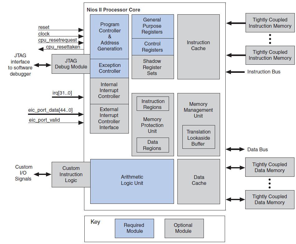
3 DE2-115: Programming Block Diagram DE2-115: Display output DE2-115: What is Nois II? DE2-115: Nois II Block Diagram 3
4 VHDL Review VHDL: an industry standard for digital circuits Very High Speed Integrated Circuits Hardware Description Language Differences from traditional programming languages Inherently parallel Mimics the behavior of digital systems Allows for the incorporation of timing requirements Describes a system as an interconnects of components VHDL Basic Syntax Basic operators <= operator for setting values ; terminator statement -- indicates a comment Keywords (few examples) and, or, not, after when, if, else, then conditionals Variable declaration Not case-semsative May use numbers, letters, underscore (no spaces) Must start with a letter and cannot end with an underscore VHDL Basic Structure Consists of 2 major parts 1. entity declaration: defines the I/O of the models entity declaration entity entity-name port (interface-signal-declaration) end entity entity-name where interface-signal-declaration is a list of signals, mode and signal_type i.e. port(signal-name(s): mode signal_type) mode: describes the direction data is transferred: in to the port, out of the port, inout bi-directional, or buffer out with feedback signal_type: describes the data type bit (std_logic) single signal having values of 0 or1, bit-vector (std_logic_vector) bus signals that have values 0 or 1* *vectors must have their range specified i.e. (3 downto 0) VHDL Basic Structure Consists of 2 major parts 2. architecture body: describes the operation of the model architecture declaration architecture architecture-name of entity-name is Declarations here: local I/O definitions (ie gates and other components) component component-name port (interface-signal-declaration) end component component-name begin architecture-body end architecture architecture-name Libraries 4
5 VHDL Library Library and Packages: A library is a place where the compiler stores information about a design project. A VHDL package is a file or module that contains declarations of commonly used objects, data type, component declarations, signal, procedures and functions that can be shared among different VHDL models. For example, std_logic is defined in the package ieee.std_logic_1164 in the ieee library. Thus, in order to use the std_logic one needs to specify the library and package at the beginning of the VHDL file using the library and the use keywords: library ieee; use ieee.std_logic_1164.all; The.all extension indicates to use all of the ieee.std_logic_1164 package. VHDL Code: 4-bit Full Adder LIBRARY ieee ; USE ieee.std logic 1164.all ; ENTITY adder IS PORT ( Cin : IN STD LOGIC ; X, Y : IN STD LOGIC VECTOR(3 DOWNTO 0) ; S : OUT STD LOGIC VECTOR(3 DOWNTO 0) ; Cout : OUT STD LOGIC ) ; END adder ; ARCHITECTURE Structure OF adder IS SIGNAL C : STD LOGIC VECTOR(1 TO 3) ; COMPONENT fulladd PORT ( Cin, x, y : IN STD LOGIC ; s, Cout : OUT STD LOGIC) ; END COMPONENT ; BEGIN stage0: fulladd PORT MAP ( Cin, X(0), Y(0), S(0), C(1) ) ; stage1: fulladd PORT MAP ( C(1), X(1), Y(1), S(1), C(2) ) ; stage2: fulladd PORT MAP ( C(2), X(2), Y(2), S(2), C(3) ) ; stage3: fulladd PORT MAP (x > X(3), y > Y(3), Cin > C(3), s > S(3), Cout > Cout ) ; END Structure ; Full Adder Example -- Example of a four bit adder library ieee; use ieee.std_logic_1164.all; -- definition of a full adder entity FULLADDER is port (a, b, c: in std_logic; sum, carry: out std_logic); end FULLADDER; architecture fulladder_behav of FULLADDER is begin sum <= (a xor b) xor c ; carry <= (a and b) or (c and (a xor b)); end fulladder_behav; 4-bit Adder Example -- 4-bit adder library ieee; use ieee.std_logic_1164.all; entity FOURBITADD is port (a, b: in std_logic_vector(3 downto 0); Cin : in std_logic; sum: out std_logic_vector (3 downto 0); Cout, V: out std_logic); end FOURBITADD; architecture fouradder_structure of FOURBITADD is signal c: std_logic_vector (4 downto 0); component FULLADDER port(a, b, c: in std_logic; sum, carry: out std_logic); end component; begin FA0: FULLADDER port map (a(0), b(0), Cin, sum(0), c(1)); FA1: FULLADDER port map (a(1), b(1), C(1), sum(1), c(2)); FA2: FULLADDER port map (a(2), b(2), C(2), sum(2), c(3)); FA3: FULLADDER port map (a(3), b(3), C(3), sum(3), c(4)); V <= c(3) xor c(4); Cout <= c(4); end fouradder_structure; 5
Review. LIBRARY list of library names; USE library.package.object; ENTITY entity_name IS generic declarations PORT ( signal_name(s): mode signal_type;
: mode signal_type;") LIBRARY list of library names; USE library.package.object; Review ENTITY entity_name IS generic declarations PORT ( signal_name(s): mode signal_type; signal_name(s) : mode signal_type); END ENTITY entity_name;
LIBRARY list of library names; USE library.package.object; Review ENTITY entity_name IS generic declarations PORT ( signal_name(s): mode signal_type; signal_name(s) : mode signal_type); END ENTITY entity_name;
Digital Systems Design
 Digital Systems Design Review of Combinatorial Circuit Building Blocks: VHDL for Combinational Circuits Dr. D. J. Jackson Lecture 2-1 Introduction to VHDL Designer writes a logic circuit description in
Concurrent Signal Assignment Statements (CSAs)
") Concurrent Signal Assignment Statements (CSAs) Digital systems operate with concurrent signals Signals are assigned values at a specific point in time. VHDL uses signal assignment statements Specify value
Concurrent Signal Assignment Statements (CSAs) Digital systems operate with concurrent signals Signals are assigned values at a specific point in time. VHDL uses signal assignment statements Specify value
Hardware Description Language VHDL (1) Introduction
 Introduction") Hardware Description Language VHDL (1) Introduction Digital Radiation Measurement and Spectroscopy NE/RHP 537 Introduction Hardware description language (HDL) Intended to describe circuits textually, for
Hardware Description Language VHDL (1) Introduction Digital Radiation Measurement and Spectroscopy NE/RHP 537 Introduction Hardware description language (HDL) Intended to describe circuits textually, for
VHDL for FPGA Design. by : Mohamed Samy
 VHDL for FPGA Design by : Mohamed Samy VHDL Vhdl is Case insensitive myvar = myvar = MYVAR IF = if = if Comments start with -- Comments can exist anywhere in the line Semi colon indicates the end of statements
Lecture 7. Standard ICs FPGA (Field Programmable Gate Array) VHDL (Very-high-speed integrated circuits. Hardware Description Language)
 VHDL (Very-high-speed integrated circuits. Hardware Description Language)") Standard ICs FPGA (Field Programmable Gate Array) VHDL (Very-high-speed integrated circuits Hardware Description Language) 1 Standard ICs PLD: Programmable Logic Device CPLD: Complex PLD FPGA: Field Programmable
Standard ICs FPGA (Field Programmable Gate Array) VHDL (Very-high-speed integrated circuits Hardware Description Language) 1 Standard ICs PLD: Programmable Logic Device CPLD: Complex PLD FPGA: Field Programmable
EE261: Intro to Digital Design
 2014 EE261: Intro to Digital Design Project 3: Four Bit Full Adder Abstract: This report serves to teach us, the students, about modeling logic and gives a chance to apply concepts from the course to a
Abi Farsoni, Department of Nuclear Engineering and Radiation Health Physics, Oregon State University
 Hardware description language (HDL) Intended to describe circuits textually, for a computer to read Evolved starting in the 1970s and 1980s Popular languages today include: VHDL Defined in 1980s by U.S.
UNIT I Introduction to VHDL VHDL: - V -VHSIC, H - Hardware, D - Description, L Language Fundamental section of a basic VHDL code Library :
 UNIT I Introduction to VHDL VHDL stands for very high-speed integrated circuit hardware description language. Which is one of the programming languages used to model a digital system by dataflow, behavioral
Mridula Allani Fall Fall
 Mridula Allani Fall 2010 Fall 2010 1 Model and document digital systems Hierarchical models System, RTL (Register Transfer Level), gates Different levels of abstraction Behavior, structure Verify circuit/system
Basic Language Concepts
 Basic Language Concepts Sudhakar Yalamanchili, Georgia Institute of Technology ECE 4170 (1) Describing Design Entities a sum b carry Primary programming abstraction is a design entity Register, logic block,
Digital Design Using VHDL Using Xilinx s Tool for Synthesis and ModelSim for Verification
 Digital Design Using VHDL Using Xilinx s Tool for Synthesis and ModelSim for Verification Ahmed Abu-Hajar, Ph.D. abuhajar@digitavid.net Digitavid, Inc San Jose, CA Session One Outline Introducing VHDL
ENGIN 241 Digital Systems with Lab
 ENGIN 241 Digital Systems with Lab (4) Dr. Honggang Zhang Engineering Department University of Massachusetts Boston 1 Introduction Hardware description language (HDL): Specifies logic function only Computer-aided
CSCI Lab 3. VHDL Syntax. Due: Tuesday, week6 Submit to: \\fs2\csci250\lab-3\
 CSCI 250 - Lab 3 VHDL Syntax Due: Tuesday, week6 Submit to: \\fs2\csci250\lab-3\ Objectives 1. Learn VHDL Valid Names 2. Learn the presentation of Assignment and Comments 3. Learn Modes, Types, Array,
Review of Digital Design with VHDL
 Review of Digital Design with VHDL Digital World Digital world is a world of 0 and 1 Each binary digit is called a bit Eight consecutive bits are called a byte Hexadecimal (base 16) representation for
VHDL Examples Mohamed Zaky
 VHDL Examples By Mohamed Zaky (mz_rasmy@yahoo.co.uk) 1 Half Adder The Half Adder simply adds 2 input bits, to produce a sum & carry output. Here we want to add A + B to produce Sum (S) and carry (C). A
Chapter 6 Combinational-Circuit Building Blocks
 Chapter 6 Combinational-Circuit Building Blocks Commonly used combinational building blocks in design of large circuits: Multiplexers Decoders Encoders Comparators Arithmetic circuits Multiplexers A multiplexer
VHDL Structural Modeling II
 VHDL Structural Modeling II ECE-331, Digital Design Prof. Hintz Electrical and Computer Engineering 5/7/2001 331_13 1 Ports and Their Usage Port Modes in reads a signal out writes a signal inout reads
ECE 448 Lecture 3. Combinational-Circuit Building Blocks. Data Flow Modeling of Combinational Logic
 ECE 448 Lecture 3 Combinational-Circuit Building Blocks Data Flow Modeling of Combinational Logic George Mason University Reading Required P. Chu, FPGA Prototyping by VHDL Examples Chapter 3, RT-level
Lattice VHDL Training
 Lattice Part I February 2000 1 VHDL Basic Modeling Structure February 2000 2 VHDL Design Description VHDL language describes a digital system as a set of modular blocks. Each modular block is described
José Costa What is an embedded system? Examples of embedded systems. Characteristics of embedded systems
 José Costa (DEI/IST) What is an Embedded System? 2012-02-14 2 / 40 What is an Embedded System? José Costa Software for Embedded Systems Department of Computer Science and Engineering (DEI) Instituto Superior
6.111 Lecture # 5. Entity section describes input and output. VHDL: Very High speed integrated circuit Description Language:
 6.111 Lecture # 5 VHDL: Very High speed integrated circuit Description Language: All VHDL files have two sections: architecture and entity -- Massachusetts (Obsolete) Stoplight Example library ieee; use
ECE 545 Lecture 5. Data Flow Modeling in VHDL. George Mason University
 ECE 545 Lecture 5 Data Flow Modeling in VHDL George Mason University Required reading P. Chu, RTL Hardware Design using VHDL Chapter 4, Concurrent Signal Assignment Statements of VHDL 2 Types of VHDL Description
Embedded System Current Trends
 Embedded System Current Trends Definition Difficult to define in current scenario. These are the computing systems which are used in electronic devices for specific purpose. Any computing system other
Digital Design Laboratory Lecture 2
 ECE 280 / CSE 280 Digital Design Laboratory Lecture 2 Adder Design Basic building block is a full adder Chained together as a ripple carry adder Carry lookahead adder is an other option Propagate and generate
CMPT 250: Computer Architecture. Using LogicWorks 5. Tutorial Part 1. Somsubhra Sharangi
 CMPT 250: Computer Architecture Using LogicWorks 5 Tutorial Part 1 Somsubhra Sharangi What is VHDL? A high level language to describe digital circuit Different that a programming language ( such as Java)
Introduction to VHDL #1
 ECE 3220 Digital Design with VHDL Introduction to VHDL #1 Lecture 3 Introduction to VHDL The two Hardware Description Languages that are most often used in industry are: n VHDL n Verilog you will learn
LECTURE 4: The VHDL N-bit Adder
 EECS 317 Computer Design LECTURE 4: The VHDL N-bit Adder Instructor: Francis G. Wolff wolff@eecs.cwru.edu Case Western Reserve University Review: N-Bit Ripple-Carry Adder Hierarchical design: 2-bit adder
ECE 545 Lecture 8. Data Flow Description of Combinational-Circuit Building Blocks. George Mason University
 ECE 545 Lecture 8 Data Flow Description of Combinational-Circuit Building Blocks George Mason University Required reading P. Chu, RTL Hardware Design using VHDL Chapter 7, Combinational Circuit Design:
Hardware Modeling. VHDL Basics. ECS Group, TU Wien
 Hardware Modeling VHDL Basics ECS Group, TU Wien VHDL Basics 2 Parts of a Design Unit Entity Architecture Configuration Package Package Package Body Library How to create a Design Unit? Interface to environment
Arithmetic Circuits. Nurul Hazlina Adder 2. Multiplier 3. Arithmetic Logic Unit (ALU) 4. HDL for Arithmetic Circuit
 4. HDL for Arithmetic Circuit") Nurul Hazlina 1 1. Adder 2. Multiplier 3. Arithmetic Logic Unit (ALU) 4. HDL for Arithmetic Circuit Nurul Hazlina 2 Introduction 1. Digital circuits are frequently used for arithmetic operations 2. Fundamental
Nurul Hazlina 1 1. Adder 2. Multiplier 3. Arithmetic Logic Unit (ALU) 4. HDL for Arithmetic Circuit Nurul Hazlina 2 Introduction 1. Digital circuits are frequently used for arithmetic operations 2. Fundamental
Lecture 4. VHDL Fundamentals. George Mason University
 Lecture 4 VHDL Fundamentals George Mason University Required reading P. Chu, RTL Hardware Design using VHDL Chapter 3, Basic Language Constructs of VHDL 2 Design Entity ECE 448 FPGA and ASIC Design with
VHDL VS VERILOG.
 1 VHDL VS VERILOG http://www.cse.cuhk.edu.hk/~mcyang/teaching.html 2 VHDL & Verilog They are both hardware description languages for modeling hardware. They are each a notation to describe the behavioral
VHDL Basics. Mehdi Modarressi. Department of Electrical and Computer Engineering, University of Tehran. ECE381(CAD), Lecture 4:
, Lecture 4:") ECE381(CAD), Lecture 4: VHDL Basics Mehdi Modarressi Department of Electrical and Computer Engineering, University of Tehran Some slides are taken (with modifications) from ECE-448 of GMU Outline An introduction
ECE381(CAD), Lecture 4: VHDL Basics Mehdi Modarressi Department of Electrical and Computer Engineering, University of Tehran Some slides are taken (with modifications) from ECE-448 of GMU Outline An introduction
2/14/2016. Hardware Synthesis. Midia Reshadi. CE Department. Entities, Architectures, and Coding.
 Hardware Synthesis MidiaReshadi CE Department Science and research branch of Islamic Azad University Email: ce.srbiau@gmail.com Midia Reshadi 1 Chapter 2 Entities, Architectures, and Coding Styles Midia
Lecture 5: Aldec Active-HDL Simulator
 Lecture 5: Aldec Active-HDL Simulator 1. Objective The objective of this tutorial is to introduce you to Aldec s Active-HDL 9.1 Student Edition simulator by performing the following tasks on a 4-bit adder
Introduction to Embedded Systems
 Introduction to Embedded Systems Minsoo Ryu Hanyang University Outline 1. Definition of embedded systems 2. History and applications 3. Characteristics of embedded systems Purposes and constraints User
ELCT 501: Digital System Design
 ELCT 501: Digital System Lecture 4: CAD tools (Continued) Dr. Mohamed Abd El Ghany, Basic VHDL Concept Via an Example Problem: write VHDL code for 1-bit adder 4-bit adder 2 1-bit adder Inputs: A (1 bit)
Digital Systems Design
 IAY 0600 Example: HalfAdder Behavior Structure Digital Systems Design a b Sum Carry 0 0 0 0 0 1 1 0 a b HalfAdder Sum Carry 1 0 1 0 VHDL discussion Dataflow Style Combinational Design 1 1 0 1 a Sum Sum
VHDL 2 Combinational Logic Circuits. Reference: Roth/John Text: Chapter 2
 VHDL 2 Combinational Logic Circuits Reference: Roth/John Text: Chapter 2 Combinational logic -- Behavior can be specified as concurrent signal assignments -- These model concurrent operation of hardware
Digital Systems Design
 IAY 0600 Digital Systems Design VHDL discussion Dataflow Style Combinational Design Tallinn University of Technology Combinational systems Combinational systems have no memory. A combinational system's
CCE 3202 Advanced Digital System Design
 CCE 3202 Advanced Digital System Design Lab Exercise #2 Introduction You will use Xilinx Webpack v9.1 to allow the synthesis and creation of VHDLbased designs. This lab will outline the steps necessary
C-Based Hardware Design
 LECTURE 6 In this lecture we will introduce: The VHDL Language and its benefits. The VHDL entity Concurrent and Sequential constructs Structural design. Hierarchy Packages Various architectures Examples
Contents. Appendix D VHDL Summary Page 1 of 23
 Appendix D VHDL Summary Page 1 of 23 Contents Appendix D VHDL Summary...2 D.1 Basic Language Elements...2 D.1.1 Comments...2 D.1.2 Identifiers...2 D.1.3 Data Objects...2 D.1.4 Data Types...2 D.1.5 Data
Experiment 8 Introduction to VHDL
 Experiment 8 Introduction to VHDL Objectives: Upon completion of this laboratory exercise, you should be able to: Enter a simple combinational logic circuit in VHDL using the Quartus II Text Editor. Assign
TUTORIAL On USING XILINX ISE FOUNDATION DESIGN TOOLS: Mixing VHDL and Schematics
 TUTORIAL On USING XILINX ISE FOUNDATION DESIGN TOOLS: Mixing VHDL and Schematics Shawki Areibi July 7, 2005 1 Introduction The objective of this tutorial is to show how VHDL can be incorporated into a
Declarations of Components and Entities are similar Components are virtual design entities entity OR_3 is
 Reserved Words component OR_3 port (A,B,C: in bit; Z: out bit); end component ; Reserved Words Declarations of Components and Entities are similar Components are virtual design entities entity OR_3 is
Introduction to VHDL #3
 ECE 322 Digital Design with VHDL Introduction to VHDL #3 Lecture 7 & 8 VHDL Modeling Styles VHDL Modeling Styles Dataflow Concurrent statements Structural Components and interconnects Behavioral (sequential)
EE 459/500 HDL Based Digital Design with Programmable Logic. Lecture 4 Introduction to VHDL
 EE 459/500 HDL Based Digital Design with Programmable Logic Lecture 4 Introduction to VHDL Read before class: Chapter 2 from textbook (first part) Outline VHDL Overview VHDL Characteristics and Concepts
Lecture 4. VHDL Fundamentals. Required reading. Example: NAND Gate. Design Entity. Example VHDL Code. Design Entity
 Required reading Lecture 4 VHDL Fundamentals P. Chu, RTL Hardware Design using VHDL Chapter 3, Basic Language Constructs of VHDL George Mason University 2 Example: NAND Gate Design Entity a b z a b z 0
Lecture 3 Introduction to VHDL
 CPE 487: Digital System Design Spring 2018 Lecture 3 Introduction to VHDL Bryan Ackland Department of Electrical and Computer Engineering Stevens Institute of Technology Hoboken, NJ 07030 1 Managing Design
Lecture 1: VHDL Quick Start. Digital Systems Design. Fall 10, Dec 17 Lecture 1 1
 Lecture 1: VHDL Quick Start Digital Systems Design Fall 10, Dec 17 Lecture 1 1 Objective Quick introduction to VHDL basic language concepts basic design methodology Use The Student s Guide to VHDL or The
Introduction to VHDL. Main language concepts
 Introduction to VHDL VHSIC (Very High Speed Integrated Circuit) Hardware Description Language Current standard is IEEE 1076-1993 (VHDL-93). Some tools still only support VHDL-87. Tools used in the lab
Multi-valued Logic. Standard Logic IEEE 1164 Type std_ulogic is ( U, uninitialized
 Multi-valued Logic Standard Logic IEEE 1164 Type std_ulogic is ( U, uninitialized X, unknown 0, logic 0 1, logic 1 Z, high impedance W, unknown L, logic 0 weak H, logic 1 weak - ); don t care Standard
VHDL: A Crash Course
 VHDL: A Crash Course Dr. Manuel Jiménez With contributions by: Irvin Ortiz Flores Electrical and Computer Engineering Department University of Puerto Rico - Mayaguez Outline Background Program Structure
1. Using the for-generahon scheme, concurrent statements can be replicated a predetermined number of times.
 Generate Statements Concurrent statements can be conditionally selected or replicated during the elaboration phase using the generate statement. There are two forms of the generate statement. 1. Using
-- Fill in values for each generic. -- Fill in values for each signal. SIGNAL load_start : std_ulogic := '1'; SIGNAL clock : std_ulogic := '0';
 -- Fill in values for each generic -- Fill in values for each signal SIGNAL load_start : std_ulogic := '1'; SIGNAL clock : std_ulogic := '0'; SIGNAL start : std_ulogic_vector(0 TO 15) := "0000000000000000";
Getting Started with Xilinx WebPack 13.1
 Getting Started with Xilinx WebPack 13.1 B. Ackland June 2011 (Adapted from S. Tewksbury notes WebPack 7.1) This tutorial is designed to help you to become familiar with the operation of the WebPack software
VHDL. Official Definition: VHSIC Hardware Description Language VHISC Very High Speed Integrated Circuit
 VHDL VHDL Official Definition: VHSIC Hardware Description Language VHISC Very High Speed Integrated Circuit VHDL Alternative (Student Generated) Definition Very Hard Digital Logic language VHDL Design
JUNE, JULY 2013 Fundamentals of HDL (10EC45) PART A
 PART A") JUNE, JULY 2013 Fundamentals of HDL (10EC45) Time: 3hrs Max Marks:100 Note: Answer FIVE full questions, selecting at least TWO questions from each part. PART A Q1.a. Describe VHDL scalar data types with
JUNE, JULY 2013 Fundamentals of HDL (10EC45) Time: 3hrs Max Marks:100 Note: Answer FIVE full questions, selecting at least TWO questions from each part. PART A Q1.a. Describe VHDL scalar data types with
VHDL for Complex Designs
 ELEC 379 : DESIGN OF DIGITAL AND MICROCOMPUTER SYSTEMS 1998/99 WINTER SESSION, TERM 2 VHDL for Complex Designs This lecture covers VHDL features that are useful when designing complex logic circuits. After
Lecture 38 VHDL Description: Addition of Two [5 5] Matrices
![Lecture 38 VHDL Description: Addition of Two [5 5] Matrices](/thumbs/83/88753861.jpg "Lecture 38 VHDL Description: Addition of Two [5 5] Matrices") Lecture 38 VHDL Description: Addition of Two [5 5] Matrices -- First, write a package to declare a two-dimensional --array with five elements library IEEE; use IEEE.STD_LOGIC_1164.all; package twodm_array
Lecture 38 VHDL Description: Addition of Two [5 5] Matrices -- First, write a package to declare a two-dimensional --array with five elements library IEEE; use IEEE.STD_LOGIC_1164.all; package twodm_array
Basic Language Constructs of VHDL
 Basic Language Constructs of VHDL Chapter 3 1 Outline 1. Basic VHDL program 2. Lexical elements and program format 3. Objects 4. Data type and operators Chapter 3 2 1. Basic VHDL program Chapter 3 3 Design
VHDL. ELEC 418 Advanced Digital Systems Dr. Ron Hayne. Images Courtesy of Cengage Learning
 VHDL ELEC 418 Advanced Digital Systems Dr. Ron Hayne Images Courtesy of Cengage Learning Design Flow 418_02 2 VHDL Modules 418_02 3 VHDL Libraries library IEEE; use IEEE.std_logic_1164.all; std_logic Single-bit
Sudhakar Yalamanchili, Georgia Institute of Technology, 2006
 Modeling Structure Sudhakar Yalamanchili, Georgia Institute of Technology, 2006 (1) Elements of Structural Models microphone To processor Micro 3284 headphones speakers amplifier Structural models describe
CprE 583 Reconfigurable Computing
 Recap Moore FSM Example CprE / ComS 583 Reconfigurable Computing Moore FSM that recognizes sequence 10 0 1 0 1 S0 / 0 S1 / 0 1 S2 / 1 Prof. Joseph Zambreno Department of Electrical and Computer Engineering
Embedded Systems CS - ES
 Embedded Systems - 1 - REVIEW Hardware/System description languages VDHL VHDL-AMS SystemC TLM - 2 - VHDL REVIEW Main goal was modeling of digital circuits Modelling at various levels of abstraction Technology-independent
What Is VHDL? VHSIC (Very High Speed Integrated Circuit) Hardware Description Language IEEE 1076 standard (1987, 1993)
 Hardware Description Language IEEE 1076 standard (1987, 1993)") What Is VHDL? VHSIC (Very High Speed Integrated Circuit) Hardware Description Language IEEE 1076 standard (1987, 1993) Only possible to synthesize logic from a subset of VHDL Subset varies according to
What Is VHDL? VHSIC (Very High Speed Integrated Circuit) Hardware Description Language IEEE 1076 standard (1987, 1993) Only possible to synthesize logic from a subset of VHDL Subset varies according to
Lecture 14 Test Bench Design
 CPE 487: Digital System Design Spring 2018 Lecture 14 Test Bench Design Bryan Ackland Department of Electrical and Computer Engineering Stevens Institute of Technology Hoboken, NJ 07030 1 Testing Digital
EECE-4740/5740 Advanced VHDL and FPGA Design. Lecture 3 Concurrent and sequential statements
 EECE-4740/5740 Advanced VHDL and FPGA Design Lecture 3 Concurrent and sequential statements Cristinel Ababei Marquette University Department of Electrical and Computer Engineering Overview Components hierarchy
Digital Design Using VHDL Using Xilinx s Tool for Synthesis and ModelSim for Verification Part II
 Digital Design Using VHDL Using Xilinx s Tool for Synthesis and ModelSim for Verification Part II Ahmed Abu-Hajar, Ph.D. abuhajar@digitavid.net Digitavid, Inc San Jose, CA VHDL Lexical Description Code
VHDL 3 BASIC OPERATORS AND ARCHITECTURE BODY. Design descriptions & design constructions examples are taken from foundation series examples
 1 VHDL 3 BASIC OPERATORS AND ARCHITECTURE BODY Design descriptions & design constructions examples are taken from foundation series examples 2 What we have done in Lab 1 entity AND_Gate is port ( a : in
Solutions - Homework 2 (Due date: October 9:30 am) Presentation and clarity are very important!
 Presentation and clarity are very important!") ECE-8L: Computer Logic Design Fall Solutions - Homework (Due date: October rd @ 9: am) Presentation and clarit are ver important! PROBLEM ( PTS) Complete the following table. Use the fewest number of bits
ECE-8L: Computer Logic Design Fall Solutions - Homework (Due date: October rd @ 9: am) Presentation and clarit are ver important! PROBLEM ( PTS) Complete the following table. Use the fewest number of bits
Tri-State Bus Implementation
 Tri-State Bus Implementation Danny Mok Altera HK FAE (dmok@altera.com) Sample Code library ieee; use ieee.std_logic_1164.all; library lpm; use lpm.lpm_components.all; entity tri_bus is port (a,b : in std_logic_vector(7
[VARIABLE declaration] BEGIN. sequential statements
![[VARIABLE declaration] BEGIN. sequential statements](/thumbs/89/98890993.jpg "[VARIABLE declaration] BEGIN. sequential statements") PROCESS statement (contains sequential statements) Simple signal assignment statement
PROCESS statement (contains sequential statements) Simple signal assignment statement
Design a 4 bit-adder. Then design a 4-7 decoder to show the outputs. Output Sum(4 bits) Adder. Output carry(1 bit)
 Adder. Output carry(1 bit)") Csc 343 Lab 2 Sep 28. 07 Objective: Design a 4 bit-adder. Then design a 4-7 decoder to show the outputs. Structure: Input A (4 bits) Input B (4 bit) Adder Output Sum(4 bits) Output carry(1 bit) input cin
Csc 343 Lab 2 Sep 28. 07 Objective: Design a 4 bit-adder. Then design a 4-7 decoder to show the outputs. Structure: Input A (4 bits) Input B (4 bit) Adder Output Sum(4 bits) Output carry(1 bit) input cin
ECE 545 Lecture 4. Simple Testbenches. George Mason University
 ECE 545 Lecture 4 Simple Testbenches George Mason University Required reading P. Chu, RTL Hardware Design using VHDL Chapter 2.2.4, Testbenches 2 Testbenches ECE 448 FPGA and ASIC Design with VHDL 3 Testbench
Lecture 3: Modeling in VHDL. EE 3610 Digital Systems
 EE 3610: Digital Systems 1 Lecture 3: Modeling in VHDL VHDL: Overview 2 VHDL VHSIC Hardware Description Language VHSIC=Very High Speed Integrated Circuit Programming language for modelling of hardware
FPGA Design Challenge :Techkriti 14 Digital Design using Verilog Part 1
 FPGA Design Challenge :Techkriti 14 Digital Design using Verilog Part 1 Anurag Dwivedi Digital Design : Bottom Up Approach Basic Block - Gates Digital Design : Bottom Up Approach Gates -> Flip Flops Digital
IE1204 Digital Design L7: Combinational circuits, Introduction to VHDL
 IE24 Digital Design L7: Combinational circuits, Introduction to VHDL Elena Dubrova KTH / ICT / ES dubrova@kth.se This lecture BV 38-339, 6-65, 28-29,34-365 IE24 Digital Design, HT 24 2 The multiplexer
Design units can NOT be split across different files
 Skeleton of a Basic VHDL Program This slide set covers the components to a basic VHDL program, including lexical elements, program format, data types and operators A VHDL program consists of a collection
Experiment 0 OR3 Gate ECE 332 Section 000 Dr. Ron Hayne June 8, 2003
 Experiment 0 OR3 Gate ECE 332 Section 000 Dr. Ron Hayne June 8, 2003 On my honor I have neither received nor given aid on this report. Signed: Ronald J. Hayne Part I Description of the Experiment Experiment
ACS College of Engineering. Department of Biomedical Engineering. Logic Design Lab pre lab questions ( ) Cycle-1
 Cycle-1") ACS College of Engineering Department of Biomedical Engineering Logic Design Lab pre lab questions (2015-2016) Cycle-1 1. What is a combinational circuit? 2. What are the various methods of simplifying
ACS College of Engineering Department of Biomedical Engineering Logic Design Lab pre lab questions (2015-2016) Cycle-1 1. What is a combinational circuit? 2. What are the various methods of simplifying
Tutorial 4 HDL. Outline VHDL PROCESS. Modeling Combinational Logic. Structural Description Instantiation and Interconnection Hierarchy
 CS3: Hardware Lab Tutorial 4 HDL Outline VHDL basic language concepts basic design methodology Examples A. Sahu Dept of Comp. Sc. & Engg. Indian Institute of Technology Guwahati i i i3 i4 Modeling Combinational
Module 2.1 Gate-Level/Structural Modeling. UNIT 2: Modeling in Verilog
 Module 2.1 Gate-Level/Structural Modeling UNIT 2: Modeling in Verilog Module in Verilog A module definition always begins with the keyword module. The module name, port list, port declarations, and optional
CS221: VHDL Models & Synthesis
 CS221: VHDL Models & Synthesis Dr. A. Sahu DeptofComp.Sc.&Engg. Indian Institute of Technology Guwahati 1 Examples : Outline N BitRipple Adder, Mux, Register, FSM VHDL Model DataFlow Component BehavioralModel
Hardware Description Languages. Modeling Complex Systems
 Hardware Description Languages Modeling Complex Systems 1 Outline (Raising the Abstraction Level) The Process Statement if-then, if-then-else, if-then-elsif, case, while, for Sensitivity list Signals vs.
Architecture des Ordinateurs I
 Architecture des Ordinateurs I Part I: VHDL and Logic Design The Language VHDL Paolo.Ienne@epfl.ch EPFL I&C LAP Recommended Books: John F. Wakerly Digital design (3rd edition) Prentice Hall, 21 Peter J.
COE 405 Design Methodology Based on VHDL
 COE 405 Design Methodology Based on VHDL Dr. Aiman H. El-Maleh Computer Engineering Department King Fahd University of Petroleum & Minerals Outline Elements of VHDL Top-Down Design Top-Down Design with
CDA 4253 FPGA System Design Introduction to VHDL. Hao Zheng Dept of Comp Sci & Eng USF
 CDA 4253 FPGA System Design Introduction to VHDL Hao Zheng Dept of Comp Sci & Eng USF Reading P. Chu, FPGA Prototyping by VHDL Examples Chapter 1, Gate-level combinational circuits Two purposes of using
Σχεδιασμός Κυκλώματος Προσαύξησης στη VHDL
 Σχεδιασμός Κυκλώματος Προσαύξησης στη VHDL Τμήμα Ηλεκτρολόγων Μηχανικών και Μηχανικών Υπολογιστών Πανεπιστήμιο Κύπρου 11-09-2013 Block Diagram of a 16-bit Adder A[0..15] B[0..1 5 Ci n 16-bit adder S[0..15]
Advanced Electronics Lab.
 College of Engineering Course Book of 2010-2011 Advanced Electronics Lab. Mr. Araz Sabir Ameen M.Sc. in Electronics & Communications ALTERA DE2 Development and Education Board DE2 Package: The DE2 package
EEL 4783: Hardware/Software Co-design with FPGAs
 EEL 4783: Hardware/Software Co-design with FPGAs Lecture 9: Short Introduction to VHDL* Prof. Mingjie Lin * Beased on notes of Turfts lecture 1 What does HDL stand for? HDL is short for Hardware Description
Computer-Aided Digital System Design VHDL
 بس م اهلل الر حم ن الر حی م Iran University of Science and Technology Department of Computer Engineering Computer-Aided Digital System Design VHDL Ramin Rajaei ramin_rajaei@ee.sharif.edu Modeling Styles
DOD, VHSIC ~1986, IEEE stnd 1987 Widely used (competition Verilog) Commercial VHDL Simulators, Synthesizers, Analyzers,etc Student texts with CDROMs
 Commercial VHDL Simulators, Synthesizers, Analyzers,etc Student texts with CDROMs") DOD, VHSIC ~1986, IEEE stnd 1987 Widely used (competition Verilog) Commercial VHDL Simulators, Synthesizers, Analyzers,etc Student texts with CDROMs Entity Architecture Blocks CAE Symbol CAE Schematic
DOD, VHSIC ~1986, IEEE stnd 1987 Widely used (competition Verilog) Commercial VHDL Simulators, Synthesizers, Analyzers,etc Student texts with CDROMs Entity Architecture Blocks CAE Symbol CAE Schematic
ECE4401 / CSE3350 ECE280 / CSE280 Digital Design Laboratory
 ECE4401 / CSE3350 ECE280 / CSE280 Digital Design Laboratory Instructor John Chandy Office: ITEB 437 Office Hours: W10-12 Tel: (860) 486-5047 Email: john.chandy@uconn chandy@uconn.edu Class home page: HuskyCT
ECE 545 Lecture 12. FPGA Resources. George Mason University
 ECE 545 Lecture 2 FPGA Resources George Mason University Recommended reading 7 Series FPGAs Configurable Logic Block: User Guide Overview Functional Details 2 What is an FPGA? Configurable Logic Blocks
FPGA BASED SYSTEM DESIGN. Dr. Tayab Din Memon Lecture 9 & 10 : Combinational and Sequential Logic
 FPGA BASED SYSTEM DESIGN Dr. Tayab Din Memon tayabuddin.memon@faculty.muet.edu.pk Lecture 9 & 10 : Combinational and Sequential Logic Combinational vs Sequential Logic Combinational logic output depends
Lecture 27. Structural Description of a 3-Bit Synchronous Decade Counter. FIGURE 4.31 A State diagram of a decade counter.
 Lecture 27 Structural Description of a 3-Bit Synchronous Decade Counter FIGURE 4.31 A State diagram of a decade counter. FIGURE 4.31B K - maps for a decade counter. FIGURE 4.32 Logic diagram of a decade