6. Combinational Circuits. Building Blocks. Digital Circuits. Wires. Q. What is a digital system? A. Digital: signals are 0 or 1.
|
|
|
- Clement Harris
- 5 years ago
- Views:
Transcription


: connected to power OFF (): not")


1 Digital Circuits 6 Combinational Circuits Q What is a digital system? A Digital: signals are or analog: signals vary continuously Q Why digital systems? A Accurate, reliable, fast, cheap Basic abstractions On, off Wire: propagates on/off value Switch: controls propagation of on/off values through wires George Boole (85 864) Claude Shannon (96 2) Applications Cell phone, ipod, antilock brakes, microprocessors, 2 Wires Building Blocks Wires ON (): connected to power OFF (): not connected to power If a wire is connected to a wire that is on, that wire is also on Typical drawing convention: "flow" from top, left to bottom, right thick wires are ON power connection thin wires are OFF 4
2 Controlled Switch Controlled Switch Controlled switch 3 connections: input, output, control Controlled switch 3 connections: input, output, control control OFF: output is connected to input control OFF input OFF output OFF control OFF input ON output ON 5 Controlled Switch Controlled Switch Controlled switch 3 connections: input, output, control control ON: output is disconnected from input Controlled switch 3 connections: input, output, control control OFF: output is connected to input control ON: output is disconnected from input control ON control OFF control ON output OFF input OFF output OFF output OFF control ON control OFF control ON output OFF input ON output ON output OFF idealized model of pass transistors found in real integrated circuits 7 8


3 Implementing a Controlled Switch Relay implementation 3 connections: input, output, control Magnetic force pulls on a contact that cuts electrical flow First Level of Abstraction Separates physical world from logical world we assume that switches operate as specified that is the only assumption physical realization of switch is irrelevant to design Physical realization dictates performance size speed power New technology immediately gives new computer Better switch? Better computer 9 Controlled Switches: A First Level of Abstraction Controlled Switches: A First Level of Abstraction Some amusing attempts to prove the point: Real-world examples that prove the point: technology switch Technology Information Switch relay pneumatic air pressure vacuum tube fluid relay water pressure electric potential transistor pass transistor in integrated circuit atom-thick transistor 2


 need more levels of abstraction to")
4 Controlled Switches: A First Level of Abstraction? Circuit Anatomy VLSI = Very Large Scale Integration Technology: Deposit materials on substrate drawing Key property: Crossing lines are controlled switches drawing Key challenge in physical world: Fabricating physical circuits with billions of controlled switches Key challenge in abstract world: Understanding behavior of circuits with billions of controlled switches circuit Bottom line: Circuit = Drawing (!) need more levels of abstraction to understand circuit behavior 3 4 Second Level of Abstraction: Logic Gates Second Level of Abstraction: Logic Gates 5 6

 AND u vwx y z abstract AND gate implementation underlying circuit")
5 Multiway Gates Multiway gates OR: if any input is ; otherwise AND: if all inputs are ; otherwise Generalized: negate some inputs Multiway Gates Multiway gates OR: if any input is ; otherwise AND: if all inputs are ; otherwise Generalized: negate some inputs tricky: see next slide 7 8 Building blocks (summary) Wires Boolean Algebra Controlled switches Gates Generalized multiway gates u v w x y z u v w x y z interpretation: value is iff variables with inverters are (and others ) AND u vwx y z abstract AND gate implementation underlying circuit simpler version 9
6 Boolean Algebra Boole Orders Lunch History Developed by Boole to solve mathematical logic problems (847) Shannon master's thesis applied it to digital circuits (937) Boolean algebra Boolean variable: value is or Boolean function: function whose inputs and outputs are, Relationship to circuits Boolean variable: signal Boolean function: circuit possibly the most important, and also the most famous, master's thesis of the [2th] century Howard Gardner Copyright 24, Sidney Harris Truth Table Truth Table for Functions of 2 Variables Truth table Systematic method to describe Boolean function One row for each possible input combination n inputs! 2 n rows Truth table 6 Boolean functions of 2 variables every 4-bit value represents one x y ZERO AND x y XOR OR x y x y truth table for all Boolean functions of 2 variables x y NOR EQ y' x' NAND ONE AND truth table truth table for all Boolean functions of 2 variables 23 24
7 Truth Table for Functions of 3 Variables Universality of AND, OR, NOT Truth table 6 Boolean functions of 2 variables 256 Boolean functions of 3 variables 2^(2^n) Boolean functions of n variables! every 4-bit value represents one every 8-bit value represents one every 2 n -bit value represents one Fact Any Boolean function can be expressed using AND, OR, NOT { AND, OR, NOT } are universal Ex: XOR(x, y) = xy' + x'y notation x' meaning NOT x x y x AND y x + y x OR y x y z AND OR MAJ ODD x y x' Expressing XOR Using AND, OR, NOT y' x'y xy' x'y + xy' x XOR y Exercise Show {AND, NOT}, {OR, NOT}, {NAND} are universal Hint DeMorgan's law: (x' y')' = x + y some functions of 3 variables Sum-of-Products Translate Boolean Formula to Boolean Circuit Sum-of-products Systematic procedure for representing a Boolean function using AND, OR, NOT Form AND term for each in Boolean function OR terms together proves that { AND, OR, NOT } are universal Sum-of-products XOR x y z MAJ x'yz xy'z xyz' xyz x'yz + xy'z + xyz' + xyz expressing MAJ using sum-of-products 27 28


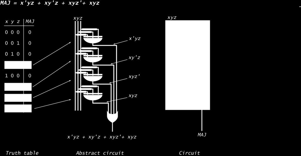
8 Translate Boolean Formula to Boolean Circuit Translate Boolean Formula to Boolean Circuit Sum-of-products XOR Key transformation from abstract to real circuit Example XOR Key transformation from abstract to real circuit AND AND AND AND 29 3 Translate Boolean Formula to Boolean Circuit Translate Boolean Formula to Boolean Circuit Example 2 Majority Example 2 Majority 3 32
 depth of circuit (time) Ex MAJ(x, y, z) = x'yz + xy'z + xyz' +")
9 Translate Boolean Formula to Boolean Circuit Translate Boolean Formula to Boolean Circuit Example 2 Majority Example 2 Majority Simplification Using Boolean Algebra Combinational Circuit Design: Summary Many possible circuits for each Boolean function Sum-of-products not necessarily optimal in: number of switches (space) depth of circuit (time) Ex MAJ(x, y, z) = x'yz + xy'z + xyz' + xyz = xy + yz + xz Problem: Compute the value of a boolean function Ingredients AND gates OR gates NOT gates Wire Instructions Step : represent input and output signals with Boolean variables Step 2: construct truth table to carry out computation Step 3: derive (simplified) Boolean expression using sum-of products Step 4: transform Boolean expression into circuit Bottom line (profound idea): It is easy to design a circuit to compute ANY boolean function size =, depth = 2 size = 7, depth = 2 35 Caveat (stay tuned): Circuit might be huge 36

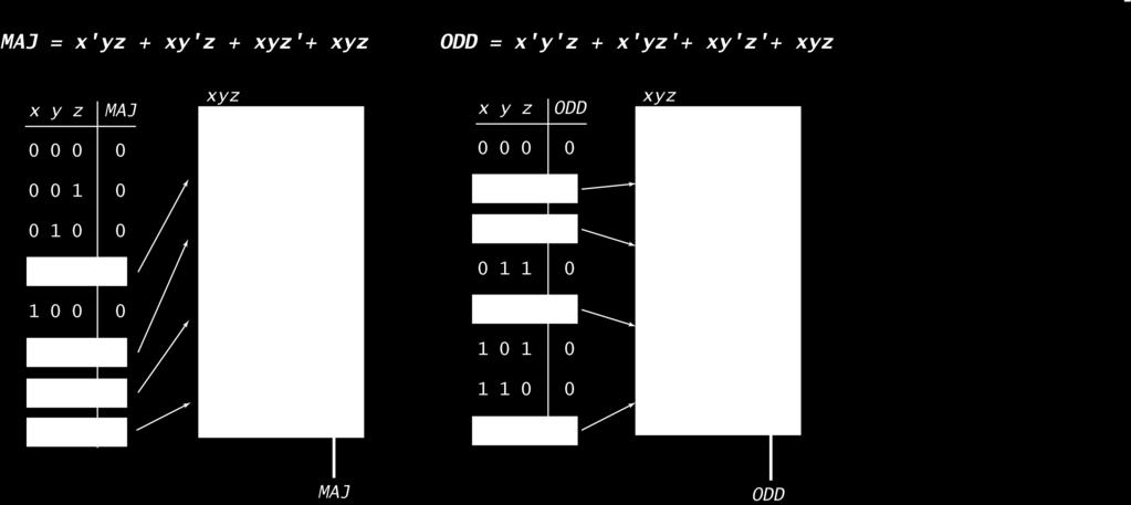
10 Translate Boolean Formula to Boolean Circuit Example 3 Odd parity if odd number of inputs are otherwise Translate Boolean Formula to Boolean Circuit Example 3 Odd parity if odd number of inputs are otherwise x y z ODD x'y'z x'yz' xy'z' xyz x'y'z + x'yz' + xy'z' + xyz Expressing ODD using sum-of-products Translate Boolean Formula to Boolean Circuit Example 3 Odd parity if odd number of inputs are otherwise Adder Circuit 39
11 Let's Make an Adder Circuit Let's Make an Adder Circuit Goal x + y = z for 4-bit integers We build 4-bit adder: 9 inputs, 4 outputs Each output bit is a boolean function of the inputs Standard method applies same idea scales to 64-bit adder in your computer Goal x + y = z for 4-bit integers Step 2 [first attempt] Build truth table c out + c in x 3 x 2 x x y 3 y 2 y y z 3 z 2 z z Step Represent input and output in binary bit adder truth table + c x 3 x 2 x x y 3 y 2 y y z 3 z 2 z z 2 8+ = 52 rows! x 3 x 2 x x + y 3 y 2 y y z 3 z 2 z z Q Why is this a bad idea? A 28-bit adder: rows >> # electrons in universe! 4 42 Let's Make an Adder Circuit Let's Make an Adder Circuit Goal x + y = z for 4-bit integers c out c 3 c = c 2 c Goal x + y = z for 4-bit integers c out c 3 c = c 2 c Step 2 Do one bit at a time! Build truth table for carry bit Build truth table for summand bit + x 3 x 2 x x y 3 y 2 y y z 3 z 2 z z Step 3 A surprise! carry bit is majority function summand bit is odd parity function + x 3 x 2 x x y 3 y 2 y y z 3 z 2 z z carry bit summand bit carry bit summand bit x i y i c i c i+ x i y i c i z i x i y i c i c i+ MAJ x i y i c i z i ODD 43 44
12 Let's Make an Adder Circuit Adder: Interface Goal x + y = z for 4-bit integers Step 4 Transform Boolean expression into circuit (use known components!) Chain together -bit adders That s it! x x x2 x3 y y y2 y3 input buses output bus z z z2 z3 A bus is a group of wires that connect (carry data values) to other components Adder: Component Level View Adder: Switch Level View x x x2 x3 y y y2 y3 input buses x x x2 x3 y y y2 y3 input buses output bus output bus z z z2 z3 z z z2 z
![Useful Combinational Circuits Decoder Adder Decoder [n-bit] n address inputs, 2 n data outputs Addressed output bit is ; others are Compact implementation of n Boolean functions Incrementer (easy,](/docs-images/87/95720567/images/13-0.jpg "add ) x x x2 z z z2 z3 z4 z5 z6 z7 Bitwise AND, XOR (easy) Decoder [next slide] Shifter (clever, but we ll skip details) Multiplexer [next lecture] 3-bit Decoder 49 5 Decoder Decoder application:")

13 Useful Combinational Circuits Decoder Adder Decoder [n-bit] n address inputs, 2 n data outputs Addressed output bit is ; others are Compact implementation of n Boolean functions Incrementer (easy, add ) x x x2 z z z2 z3 z4 z5 z6 z7 Bitwise AND, XOR (easy) Decoder [next slide] Shifter (clever, but we ll skip details) Multiplexer [next lecture] 3-bit Decoder 49 5 Decoder Decoder application: Your computer s ALU! Decoder [n-bit] n address inputs, 2 n data outputs Addressed output bit is ; others are Compact implementation of n Boolean functions ALU: Arithmetic and Logic Unit implements instructions input, output connects to registers via buses -bit input buses TOY opcode bits sub x x x2 z z z2 z3 z4 z5 z6 z7 Ex: TOY-Lite ( bit words) : add 2: subtract 3: and 4: xor 5: shift left 6: shift right add and xor shift right 3-bit Decoder Details: All circuits compute their result Decoder lines AND all results one-hot OR collects answer -bit output bus 5 52


![[AND, OR, NOT] Boolean circuit](/docs-images/87/95720567/images/14-5.jpg "[MAJ, ODD] Adder Shifter")
14 Summary Lessons for software design apply to hardware design! Interface describes behavior of circuit Implementation gives details of how to build it Layers of abstraction apply with a vengeance! On/off Controlled switch [relay, transistor] Gates [AND, OR, NOT] Boolean circuit [MAJ, ODD] Adder Shifter Arithmetic logic unit TOY machine (stay tuned) Your computer 53
Combinational Circuits
 Combinational Circuits Q. What is a combinational circuit? A. Digital: signals are or. A. No feedback: no loops. analog circuits: signals vary continuously sequential circuits: loops allowed (stay tuned)
6.1 Combinational Circuits. George Boole ( ) Claude Shannon ( )
 Claude Shannon ( )") 6. Combinational Circuits George Boole (85 864) Claude Shannon (96 2) Digital signals Binary (or logical ) values: or, on or off, high or low voltage Wires. Propagate logical values from place to place.
6. Combinational Circuits George Boole (85 864) Claude Shannon (96 2) Digital signals Binary (or logical ) values: or, on or off, high or low voltage Wires. Propagate logical values from place to place.
6.1 Combinational Circuits. George Boole ( ) Claude Shannon ( )
 Claude Shannon ( )") 6. Combinational Circuits George Boole (85 864) Claude Shannon (96 2) Signals and Wires Digital signals Binary (or logical ) values: or, on or off, high or low voltage Wires. Propagate digital signals
6. Combinational Circuits George Boole (85 864) Claude Shannon (96 2) Signals and Wires Digital signals Binary (or logical ) values: or, on or off, high or low voltage Wires. Propagate digital signals
Lecture 10: Combinational Circuits
 Computer Architecture Lecture : Combinational Circuits Previous two lectures.! TOY machine. Net two lectures.! Digital circuits. George Boole (85 864) Claude Shannon (96 2) Culminating lecture.! Putting
6: Combinational Circuits
 Computer Architecture 6: Combinational Circuits Previous two lectures. von Neumann machine. This lectures. Boolean circuits. Later in the course. Putting it all together and building a TOY machine. George
Arithmetic Logic Unit (ALU)
") Arithmetic Logic Unit (ALU) Introduction to Computer Yung-Yu Chuang with slides by Sedgewick & Wayne (introcs.cs.princeton.edu), Nisan & Schocken (www.nand2tetris.org) and Harris & Harris (DDCA) Let's
Arithmetic Logic Unit (ALU) Introduction to Computer Yung-Yu Chuang with slides by Sedgewick & Wayne (introcs.cs.princeton.edu), Nisan & Schocken (www.nand2tetris.org) and Harris & Harris (DDCA) Let's
Combinational Circuits Digital Logic (Materials taken primarily from:
 Combinational Circuits Digital Logic (Materials taken primarily from: http://www.facstaff.bucknell.edu/mastascu/elessonshtml/eeindex.html http://www.cs.princeton.edu/~cos126 ) Digital Systems What is a
Boolean logic. Boolean Algebra. Introduction to Computer Yung-Yu Chuang NOT AND NOT
 oolean lgebra oolean logic ased on symbolic logic, designed by George oole oolean variables take values as or. oolean expressions created from: NOT, ND, OR Introduction to Computer ung-u Chuang with slides
Software and Hardware
 Software and Hardware Numbers At the most fundamental level, a computer manipulates electricity according to specific rules To make those rules produce something useful, we need to associate the electrical
60-265: Winter ANSWERS Exercise 4 Combinational Circuit Design
 60-265: Winter 2010 Computer Architecture I: Digital Design ANSWERS Exercise 4 Combinational Circuit Design Question 1. One-bit Comparator [ 1 mark ] Consider two 1-bit inputs, A and B. If we assume that
QUESTION BANK FOR TEST
 CSCI 2121 Computer Organization and Assembly Language PRACTICE QUESTION BANK FOR TEST 1 Note: This represents a sample set. Please study all the topics from the lecture notes. Question 1. Multiple Choice
Computer Organization and Levels of Abstraction
 Computer Organization and Levels of Abstraction Announcements Today: PS 7 Lab 8: Sound Lab tonight bring machines and headphones! PA 7 Tomorrow: Lab 9 Friday: PS8 Today (Short) Floating point review Boolean
Lecture (04) Boolean Algebra and Logic Gates
 Boolean Algebra and Logic Gates") Lecture (4) Boolean Algebra and Logic Gates By: Dr. Ahmed ElShafee ١ Dr. Ahmed ElShafee, ACU : Spring 26, Logic Design Boolean algebra properties basic assumptions and properties: Closure law A set S is
Lecture (4) Boolean Algebra and Logic Gates By: Dr. Ahmed ElShafee ١ Dr. Ahmed ElShafee, ACU : Spring 26, Logic Design Boolean algebra properties basic assumptions and properties: Closure law A set S is
Lecture (04) Boolean Algebra and Logic Gates By: Dr. Ahmed ElShafee
 Boolean Algebra and Logic Gates By: Dr. Ahmed ElShafee") Lecture (4) Boolean Algebra and Logic Gates By: Dr. Ahmed ElShafee Boolean algebra properties basic assumptions and properties: Closure law A set S is closed with respect to a binary operator, for every
Lecture (4) Boolean Algebra and Logic Gates By: Dr. Ahmed ElShafee Boolean algebra properties basic assumptions and properties: Closure law A set S is closed with respect to a binary operator, for every
Chapter 3. Boolean Algebra and Digital Logic
 Chapter 3 Boolean Algebra and Digital Logic Chapter 3 Objectives Understand the relationship between Boolean logic and digital computer circuits. Learn how to design simple logic circuits. Understand how
Henry Lin, Department of Electrical and Computer Engineering, California State University, Bakersfield Lecture 7 (Digital Logic) July 24 th, 2012
 July 24 th, 2012") Henry Lin, Department of Electrical and Computer Engineering, California State University, Bakersfield Lecture 7 (Digital Logic) July 24 th, 2012 1 Digital vs Analog Digital signals are binary; analog
Henry Lin, Department of Electrical and Computer Engineering, California State University, Bakersfield Lecture 7 (Digital Logic) July 24 th, 2012 1 Digital vs Analog Digital signals are binary; analog
1. Mark the correct statement(s)
") 1. Mark the correct statement(s) 1.1 A theorem in Boolean algebra: a) Can easily be proved by e.g. logic induction b) Is a logical statement that is assumed to be true, c) Can be contradicted by another
1. Mark the correct statement(s) 1.1 A theorem in Boolean algebra: a) Can easily be proved by e.g. logic induction b) Is a logical statement that is assumed to be true, c) Can be contradicted by another
Gate-Level Minimization. BME208 Logic Circuits Yalçın İŞLER
 Gate-Level Minimization BME28 Logic Circuits Yalçın İŞLER islerya@yahoo.com http://me.islerya.com Complexity of Digital Circuits Directly related to the complexity of the algebraic expression we use to
Propositional Calculus. Math Foundations of Computer Science
 Propositional Calculus Math Foundations of Computer Science Propositional Calculus Objective: To provide students with the concepts and techniques from propositional calculus so that they can use it to
UNIT 2 BOOLEAN ALGEBRA
 UNIT 2 BOOLEN LGEBR Spring 2 2 Contents Introduction Basic operations Boolean expressions and truth tables Theorems and laws Basic theorems Commutative, associative, and distributive laws Simplification
Computer Organization and Levels of Abstraction
 Computer Organization and Levels of Abstraction Announcements PS8 Due today PS9 Due July 22 Sound Lab tonight bring machines and headphones! Binary Search Today Review of binary floating point notation
Combinational Logic & Circuits
 Week-I Combinational Logic & Circuits Spring' 232 - Logic Design Page Overview Binary logic operations and gates Switching algebra Algebraic Minimization Standard forms Karnaugh Map Minimization Other
END-TERM EXAMINATION
 (Please Write your Exam Roll No. immediately) END-TERM EXAMINATION DECEMBER 2006 Exam. Roll No... Exam Series code: 100919DEC06200963 Paper Code: MCA-103 Subject: Digital Electronics Time: 3 Hours Maximum
Boolean algebra. June 17, Howard Huang 1
 Boolean algebra Yesterday we talked about how analog voltages can represent the logical values true and false. We introduced the basic Boolean operations AND, OR and NOT, which can be implemented in hardware
BUILDING BLOCKS OF A BASIC MICROPROCESSOR. Part 1 PowerPoint Format of Lecture 3 of Book
 BUILDING BLOCKS OF A BASIC MICROPROCESSOR Part PowerPoint Format of Lecture 3 of Book Decoder Tri-state device Full adder, full subtractor Arithmetic Logic Unit (ALU) Memories Example showing how to write
Electronic Engineering Part 1 Laboratory Experiment. Digital Circuit Design 1 Combinational Logic. (3 hours)
") Electronic Engineering Part 1 Laboratory Experiment Digital Circuit Design 1 Combinational Logic (3 hours) 1. Introduction These days most signal processing is done digitally. Electronic signals (representing
Electronic Engineering Part 1 Laboratory Experiment Digital Circuit Design 1 Combinational Logic (3 hours) 1. Introduction These days most signal processing is done digitally. Electronic signals (representing
Digital Logic Design Exercises. Assignment 1
 Assignment 1 For Exercises 1-5, match the following numbers with their definition A Number Natural number C Integer number D Negative number E Rational number 1 A unit of an abstract mathematical system
CS61C : Machine Structures
 inst.eecs.berkeley.edu/~cs61c/su06 CS61C : Machine Structures Lecture #14: Combinational Logic, Gates, and State 2006-07-20 CS 61C L14 Combinational Logic (1) Andy Carle What are Machine Structures? Software
Department of Electrical Engineering McGill University ECSE 221 Introduction to Computer Engineering Assignment 2 Combinational Logic
 Department of Electrical Engineering McGill University ECSE 221 Introduction to Computer Engineering Assignment 2 Combinational Logic Question 1: Due October 19 th, 2009 A convenient shorthand for specifying
Arab Open University. Computer Organization and Architecture - T103
 Arab Open University Computer Organization and Architecture - T103 Reference Book: Linda Null, Julia Lobur, The essentials of Computer Organization and Architecture, Jones & Bartlett, Third Edition, 2012.
Von Neumann Architecture
 Von Neumann Architecture Assist lecturer Donya A. Khalid Lecture 2 2/29/27 Computer Organization Introduction In 945, just after the World War, Jon Von Neumann proposed to build a more flexible computer.
Boolean Logic CS.352.F12
 Boolean Logic CS.352.F12 Boolean Algebra Boolean Algebra Mathematical system used to manipulate logic equations. Boolean: deals with binary values (True/False, yes/no, on/off, 1/0) Algebra: set of operations
Boolean Algebra & Digital Logic
 Boolean Algebra & Digital Logic Boolean algebra was developed by the Englishman George Boole, who published the basic principles in the 1854 treatise An Investigation of the Laws of Thought on Which to
Parallel logic circuits
 Computer Mathematics Week 9 Parallel logic circuits College of Information cience and Engineering Ritsumeikan University last week the mathematics of logic circuits the foundation of all digital design
Introduction to Boolean logic and Logical Gates
 Introduction to Boolean logic and Logical Gates Institute of Statistics Fall 2014 We saw the importance of the binary number system for data representation in a computer system. We ll see that the construction
211: Computer Architecture Summer 2016
 211: Computer Architecture Summer 2016 Liu Liu Topic: Storage Project3 Digital Logic - Storage: Recap - Direct - Mapping - Fully Associated - 2-way Associated - Cache Friendly Code Rutgers University Liu
4. Write a sum-of-products representation of the following circuit. Y = (A + B + C) (A + B + C)
 (A + B + C)") COP 273, Winter 26 Exercises 2 - combinational logic Questions. How many boolean functions can be defined on n input variables? 2. Consider the function: Y = (A B) (A C) B (a) Draw a combinational logic
COP 273, Winter 26 Exercises 2 - combinational logic Questions. How many boolean functions can be defined on n input variables? 2. Consider the function: Y = (A B) (A C) B (a) Draw a combinational logic
Review. EECS Components and Design Techniques for Digital Systems. Lec 05 Boolean Logic 9/4-04. Seq. Circuit Behavior. Outline.
 Review EECS 150 - Components and Design Techniques for Digital Systems Lec 05 Boolean Logic 94-04 David Culler Electrical Engineering and Computer Sciences University of California, Berkeley Design flow
ECE 341 Midterm Exam
 ECE 341 Midterm Exam Time allowed: 75 minutes Total Points: 75 Points Scored: Name: Problem No. 1 (8 points) For each of the following statements, indicate whether the statement is TRUE or FALSE: (a) A
1. Prove that if you have tri-state buffers and inverters, you can build any combinational logic circuit. [4]
![1. Prove that if you have tri-state buffers and inverters, you can build any combinational logic circuit. [4]](/thumbs/81/83055464.jpg "1. Prove that if you have tri-state buffers and inverters, you can build any combinational logic circuit. [4]") HW 3 Answer Key 1. Prove that if you have tri-state buffers and inverters, you can build any combinational logic circuit. [4] You can build a NAND gate from tri-state buffers and inverters and thus you
HW 3 Answer Key 1. Prove that if you have tri-state buffers and inverters, you can build any combinational logic circuit. [4] You can build a NAND gate from tri-state buffers and inverters and thus you
Lecture (05) Boolean Algebra and Logic Gates
 Boolean Algebra and Logic Gates") Lecture (05) Boolean Algebra and Logic Gates By: Dr. Ahmed ElShafee ١ Minterms and Maxterms consider two binary variables x and y combined with an AND operation. Since eachv ariable may appear in either
Lecture (05) Boolean Algebra and Logic Gates By: Dr. Ahmed ElShafee ١ Minterms and Maxterms consider two binary variables x and y combined with an AND operation. Since eachv ariable may appear in either
CS 31: Intro to Systems Digital Logic. Kevin Webb Swarthmore College February 3, 2015
 CS 31: Intro to Systems Digital Logic Kevin Webb Swarthmore College February 3, 2015 Reading Quiz Today Hardware basics Machine memory models Digital signals Logic gates Circuits: Borrow some paper if
Boolean Algebra and Logic Gates
 Boolean Algebra and Logic Gates Binary logic is used in all of today's digital computers and devices Cost of the circuits is an important factor Finding simpler and cheaper but equivalent circuits can
Chapter 3. Gate-Level Minimization. Outlines
 Chapter 3 Gate-Level Minimization Introduction The Map Method Four-Variable Map Five-Variable Map Outlines Product of Sums Simplification Don t-care Conditions NAND and NOR Implementation Other Two-Level
Chapter 2: Combinational Systems
 Uchechukwu Ofoegbu Chapter 2: Combinational Systems Temple University Adapted from Alan Marcovitz s Introduction to Logic and Computer Design Riddle Four switches can be turned on or off. One is the switch
CS 31: Intro to Systems Digital Logic. Kevin Webb Swarthmore College February 2, 2016
 CS 31: Intro to Systems Digital Logic Kevin Webb Swarthmore College February 2, 2016 Reading Quiz Today Hardware basics Machine memory models Digital signals Logic gates Circuits: Borrow some paper if
LECTURE 4. Logic Design
 LECTURE 4 Logic Design LOGIC DESIGN The language of the machine is binary that is, sequences of 1 s and 0 s. But why? At the hardware level, computers are streams of signals. These signals only have two
Introduction to Boole algebra. Binary algebra
 Introduction to Boole algebra Binary algebra Boole algebra George Boole s book released in 1847 We have only two digits: true and false We have NOT, AND, OR, XOR etc operations We have axioms and theorems
This podcast will demonstrate a logical approach as to how a computer adds through logical gates.
 This podcast will demonstrate a logical approach as to how a computer adds through logical gates. A computer is a programmable machine that receives input, stores and manipulates data, and provides output
01 Introduction to Digital Logic. ENGR 3410 Computer Architecture Mark L. Chang Fall 2008
 Introduction to Digital Logic ENGR 34 Computer Architecture Mark L. Chang Fall 28 Acknowledgements Patterson & Hennessy: Book & Lecture Notes Patterson s 997 course notes (U.C. Berkeley CS 52, 997) Tom
Circuit analysis summary
 Boolean Algebra Circuit analysis summary After finding the circuit inputs and outputs, you can come up with either an expression or a truth table to describe what the circuit does. You can easily convert
Logic Design (Part 2) Combinational Logic Circuits (Chapter 3)
 Combinational Logic Circuits (Chapter 3)") Digital Logic Circuits Logic Design (Part ) Combinational Logic Circuits (Chapter 3) ² We saw how we can build the simple logic gates using transistors ² Use these gates as building blocks to build more
Digital Logic Circuits Logic Design (Part ) Combinational Logic Circuits (Chapter 3) ² We saw how we can build the simple logic gates using transistors ² Use these gates as building blocks to build more
Arithmetic Circuits. Design of Digital Circuits 2014 Srdjan Capkun Frank K. Gürkaynak.
 Arithmetic Circuits Design of Digital Circuits 2014 Srdjan Capkun Frank K. Gürkaynak http://www.syssec.ethz.ch/education/digitaltechnik_14 Adapted from Digital Design and Computer Architecture, David Money
01 Introduction to Digital Logic. ENGR 3410 Computer Architecture Mark L. Chang Fall 2006
 Introduction to Digital Logic ENGR 34 Computer Architecture Mark L. Chang Fall 26 Acknowledgements Patterson & Hennessy: Book & Lecture Notes Patterson s 997 course notes (U.C. Berkeley CS 52, 997) Tom
CS 261 Fall Mike Lam, Professor. Combinational Circuits
 CS 261 Fall 2017 Mike Lam, Professor Combinational Circuits The final frontier Java programs running on Java VM C programs compiled on Linux Assembly / machine code on CPU + memory??? Switches and electric
Objectives: 1- Bolean Algebra. Eng. Ayman Metwali
 Objectives: Chapter 3 : 1- Boolean Algebra Boolean Expressions Boolean Identities Simplification of Boolean Expressions Complements Representing Boolean Functions 2- Logic gates 3- Digital Components 4-
ECE 2030B 1:00pm Computer Engineering Spring problems, 5 pages Exam Two 10 March 2010
 Instructions: This is a closed book, closed note exam. Calculators are not permitted. If you have a question, raise your hand and I will come to you. Please work the exam in pencil and do not separate
ECEN 468 Advanced Logic Design
 ECEN 468 Advanced Logic Design Lecture 26: Verilog Operators ECEN 468 Lecture 26 Operators Operator Number of Operands Result Arithmetic 2 Binary word Bitwise 2 Binary word Reduction 1 Bit Logical 2 Boolean
IST 4 Information and Logic
 IST 4 Information and Logic T = today x= hw#x out x= hw#x due mon tue wed thr 28 M oh 4 oh M oh oh 2 M2 8 oh oh 2 fri oh oh = office hours oh 25 oh M2 2 3 oh T midterms oh Mx= MQx out 9 oh 3 4 oh Mx= MQx
UPY14602-DIGITAL ELECTRONICS AND MICROPROCESSORS Lesson Plan
 UPY14602-DIGITAL ELECTRONICS AND MICROPROCESSORS Lesson Plan UNIT I - NUMBER SYSTEMS AND LOGIC GATES Introduction to decimal- Binary- Octal- Hexadecimal number systems-inter conversions-bcd code- Excess
Simplification of Boolean Functions
 Simplification of Boolean Functions Contents: Why simplification? The Map Method Two, Three, Four and Five variable Maps. Simplification of two, three, four and five variable Boolean function by Map method.
BOOLEAN ALGEBRA. Logic circuit: 1. From logic circuit to Boolean expression. Derive the Boolean expression for the following circuits.
 COURSE / CODE DIGITAL SYSTEMS FUNDAMENTAL (ECE 421) DIGITAL ELECTRONICS FUNDAMENTAL (ECE 422) BOOLEAN ALGEBRA Boolean Logic Boolean logic is a complete system for logical operations. It is used in countless
Gate-Level Minimization. section instructor: Ufuk Çelikcan
 Gate-Level Minimization section instructor: Ufuk Çelikcan Compleity of Digital Circuits Directly related to the compleity of the algebraic epression we use to build the circuit. Truth table may lead to
CS8803: Advanced Digital Design for Embedded Hardware
 CS883: Advanced Digital Design for Embedded Hardware Lecture 2: Boolean Algebra, Gate Network, and Combinational Blocks Instructor: Sung Kyu Lim (limsk@ece.gatech.edu) Website: http://users.ece.gatech.edu/limsk/course/cs883
Propositional Calculus: Boolean Algebra and Simplification. CS 270: Mathematical Foundations of Computer Science Jeremy Johnson
 Propositional Calculus: Boolean Algebra and Simplification CS 270: Mathematical Foundations of Computer Science Jeremy Johnson Propositional Calculus Topics Motivation: Simplifying Conditional Expressions
Experiment 3: Logic Simplification
 Module: Logic Design Name:... University no:.. Group no:. Lab Partner Name: Mr. Mohamed El-Saied Experiment : Logic Simplification Objective: How to implement and verify the operation of the logical functions
COMBINATIONAL LOGIC CIRCUITS
 COMBINATIONAL LOGIC CIRCUITS 4.1 INTRODUCTION The digital system consists of two types of circuits, namely: (i) Combinational circuits and (ii) Sequential circuits A combinational circuit consists of logic
ELCT201: DIGITAL LOGIC DESIGN
 ELCT201: DIGITAL LOGIC DESIGN Dr. Eng. Haitham Omran, haitham.omran@guc.edu.eg Dr. Eng. Wassim Alexan, wassim.joseph@guc.edu.eg Lecture 3 Following the slides of Dr. Ahmed H. Madian محرم 1439 ه Winter
Reference Sheet for C112 Hardware
 Reference Sheet for C112 Hardware 1 Boolean Algebra, Gates and Circuits Autumn 2016 Basic Operators Precedence : (strongest),, + (weakest). AND A B R 0 0 0 0 1 0 1 0 0 1 1 1 OR + A B R 0 0 0 0 1 1 1 0
Computer Systems. Binary Representation. Binary Representation. Logical Computation: Boolean Algebra
 Binary Representation Computer Systems Information is represented as a sequence of binary digits: Bits What the actual bits represent depends on the context: Seminar 3 Numerical value (integer, floating
Gate Level Minimization Map Method
 Gate Level Minimization Map Method Complexity of hardware implementation is directly related to the complexity of the algebraic expression Truth table representation of a function is unique Algebraically
CS 261 Fall Mike Lam, Professor. Logic Gates
 CS 261 Fall 2016 Mike Lam, Professor Logic Gates The final frontier Java programs running on Java VM C programs compiled on Linux Assembly / machine code on CPU + memory??? Switches and electric signals
Chapter 3: part 3 Binary Subtraction
 Chapter 3: part 3 Binary Subtraction Iterative combinational circuits Binary adders Half and full adders Ripple carry and carry lookahead adders Binary subtraction Binary adder-subtractors Signed binary
Chapter 4. Combinational Logic. Dr. Abu-Arqoub
 Chapter 4 Combinational Logic Introduction N Input Variables Combinational Logic Circuit M Output Variables 2 Design Procedure The problem is stated 2 The number of available input variables & required
Code No: 07A3EC03 Set No. 1
 Code No: 07A3EC03 Set No. 1 II B.Tech I Semester Regular Examinations, November 2008 SWITCHING THEORY AND LOGIC DESIGN ( Common to Electrical & Electronic Engineering, Electronics & Instrumentation Engineering,
Binary Adders: Half Adders and Full Adders
 Binary Adders: Half Adders and Full Adders In this set of slides, we present the two basic types of adders: 1. Half adders, and 2. Full adders. Each type of adder functions to add two binary bits. In order
Chapter 2 Boolean algebra and Logic Gates
 Chapter 2 Boolean algebra and Logic Gates 2. Introduction In working with logic relations in digital form, we need a set of rules for symbolic manipulation which will enable us to simplify complex expressions
Bawar Abid Abdalla. Assistant Lecturer Software Engineering Department Koya University
 Logic Design First Stage Lecture No.5 Boolean Algebra Bawar Abid Abdalla Assistant Lecturer Software Engineering Department Koya University Boolean Operations Laws of Boolean Algebra Rules of Boolean Algebra
Chapter 2. Boolean Expressions:
 Chapter 2 Boolean Expressions: A Boolean expression or a function is an expression which consists of binary variables joined by the Boolean connectives AND and OR along with NOT operation. Any Boolean
Chapter 2. Boolean Algebra and Logic Gates
 Chapter 2. Boolean Algebra and Logic Gates Tong In Oh 1 Basic Definitions 2 3 2.3 Axiomatic Definition of Boolean Algebra Boolean algebra: Algebraic structure defined by a set of elements, B, together
ECE 2030D Computer Engineering Spring problems, 5 pages Exam Two 8 March 2012
 Instructions: This is a closed book, closed note exam. Calculators are not permitted. If you have a question, raise your hand and I will come to you. Please work the exam in pencil and do not separate
Lecture Topics. Announcements. Today: Integer Arithmetic (P&H ) Next: continued. Consulting hours. Introduction to Sim. Milestone #1 (due 1/26)
 Next: continued. Consulting hours. Introduction to Sim. Milestone #1 (due 1/26)") Lecture Topics Today: Integer Arithmetic (P&H 3.1-3.4) Next: continued 1 Announcements Consulting hours Introduction to Sim Milestone #1 (due 1/26) 2 1 Overview: Integer Operations Internal representation
Lecture Topics Today: Integer Arithmetic (P&H 3.1-3.4) Next: continued 1 Announcements Consulting hours Introduction to Sim Milestone #1 (due 1/26) 2 1 Overview: Integer Operations Internal representation
Standard Forms of Expression. Minterms and Maxterms
 Standard Forms of Expression Minterms and Maxterms Standard forms of expressions We can write expressions in many ways, but some ways are more useful than others A sum of products (SOP) expression contains:
Chapter 4 Arithmetic Functions
 Logic and Computer Design Fundamentals Chapter 4 Arithmetic Functions Charles Kime & Thomas Kaminski 2008 Pearson Education, Inc. (Hyperlinks are active in View Show mode) Overview Iterative combinational
Boolean Algebra. BME208 Logic Circuits Yalçın İŞLER
 Boolean Algebra BME28 Logic Circuits Yalçın İŞLER islerya@yahoo.com http://me.islerya.com 5 Boolean Algebra /2 A set of elements B There exist at least two elements x, y B s. t. x y Binary operators: +
Digital Techniques. Lecture 1. 1 st Class
 Digital Techniques Lecture 1 1 st Class Digital Techniques Digital Computer and Digital System: Digital computer is a part of digital system, it based on binary system. A block diagram of digital computer
 Get Free notes at Module-I One s Complement: Complement all the bits.i.e. makes all 1s as 0s and all 0s as 1s Two s Complement: One s complement+1 SIGNED BINARY NUMBERS Positive integers (including zero)
Data III & Integers I
 Data III & Integers I CSE 351 Spring 2017 Instructor: Ruth Anderson Teaching Assistants: Dylan Johnson Kevin Bi Linxing Preston Jiang Cody Ohlsen Yufang Sun Joshua Curtis Administrivia Everyone has VM
Addition and multiplication
 Addition and multiplication Arithmetic is the most basic thing you can do with a computer, but it s not as easy as you might expect! These next few lectures focus on addition, subtraction, multiplication
Chapter 2 Basic Logic Circuits and VHDL Description
 Chapter 2 Basic Logic Circuits and VHDL Description We cannot solve our problems with the same thinking we used when we created them. ----- Albert Einstein Like a C or C++ programmer don t apply the logic.
2.1 Binary Logic and Gates
 1 EED2003 Digital Design Presentation 2: Boolean Algebra Asst. Prof.Dr. Ahmet ÖZKURT Asst. Prof.Dr Hakkı T. YALAZAN Based on the Lecture Notes by Jaeyoung Choi choi@comp.ssu.ac.kr Fall 2000 2.1 Binary
Digital Systems. Jinkyu Jeong Computer Systems Laboratory Sungkyunkwan University
 Digital Systems Jinkyu Jeong (jinkyu@skku.edu) Computer Systems Laboratory Sungkyunkwan University http://csl.skku.edu SSE2030: Introduction to Computer Systems, Spring 2018, Jinkyu Jeong (jinkyu@skku.edu)
Date Performed: Marks Obtained: /10. Group Members (ID):. Experiment # 09 MULTIPLEXERS
:. Experiment # 09 MULTIPLEXERS") Name: Instructor: Engr. Date Performed: Marks Obtained: /10 Group Members (ID):. Checked By: Date: Experiment # 09 MULTIPLEXERS OBJECTIVES: To experimentally verify the proper operation of a multiplexer.
Name: Instructor: Engr. Date Performed: Marks Obtained: /10 Group Members (ID):. Checked By: Date: Experiment # 09 MULTIPLEXERS OBJECTIVES: To experimentally verify the proper operation of a multiplexer.
Menu. Algebraic Simplification - Boolean Algebra EEL3701 EEL3701. MSOP, MPOS, Simplification
 Menu Minterms & Maxterms SOP & POS MSOP & MPOS Simplification using the theorems/laws/axioms Look into my... 1 Definitions (Review) Algebraic Simplification - Boolean Algebra Minterms (written as m i ):
Review. Pipeline big-delay CL for faster clock Finite State Machines extremely useful You ll see them again in 150, 152 & 164
 CS61C L17 Combinatorial Logic Blocks (1) inst.eecs.berkeley.edu/~cs61c CS61C : Machine Structures Lecture #17 Combinatorial Logic Blocks 2007-7-24 Scott Beamer, Instructor Review Pipeline big-delay CL
Basic Arithmetic (adding and subtracting)
") Basic Arithmetic (adding and subtracting) Digital logic to show add/subtract Boolean algebra abstraction of physical, analog circuit behavior 1 0 CPU components ALU logic circuits logic gates transistors
Basic Arithmetic (adding and subtracting) Digital logic to show add/subtract Boolean algebra abstraction of physical, analog circuit behavior 1 0 CPU components ALU logic circuits logic gates transistors
EE292: Fundamentals of ECE
 EE292: Fundamentals of ECE Fall 2012 TTh 10:00-11:15 SEB 1242 Lecture 22 121115 http://www.ee.unlv.edu/~b1morris/ee292/ 2 Outline Review Binary Number Representation Binary Arithmetic Combinatorial Logic
II/IV B.Tech (Regular/Supplementary) DEGREE EXAMINATION. Answer ONE question from each unit.
 DEGREE EXAMINATION. Answer ONE question from each unit.") Hall Ticket Number: 14CS IT303 November, 2017 Third Semester Time: Three Hours Answer Question No.1 compulsorily. II/IV B.Tech (Regular/Supplementary) DEGREE EXAMINATION Common for CSE & IT Digital Logic
Hall Ticket Number: 14CS IT303 November, 2017 Third Semester Time: Three Hours Answer Question No.1 compulsorily. II/IV B.Tech (Regular/Supplementary) DEGREE EXAMINATION Common for CSE & IT Digital Logic
IT 201 Digital System Design Module II Notes
 IT 201 Digital System Design Module II Notes BOOLEAN OPERATIONS AND EXPRESSIONS Variable, complement, and literal are terms used in Boolean algebra. A variable is a symbol used to represent a logical quantity.
Review: Chip Design Styles
 MPT-50 Introduction to omputer Design SFU, Harbour entre, Spring 007 Lecture 9: Feb. 6, 007 Programmable Logic Devices (PLDs) - Read Only Memory (ROM) - Programmable Array Logic (PAL) - Programmable Logic